Any UHF receiver is suitable for receiving free-to-air digital television broadcasting; the broadcast quality of the signal can be influenced by careful selection of the antenna. If the principle of operation of a television antenna is clear, and you like to experiment and also save money, then it is better to make it yourself . In most cases, passive antennas , since these devices do not include complex technical devices. But the absence of microcircuits and other electronics does not apply to active types of TV signal catchers. Regardless of what type of receiving antenna technology you decide to make from scrap materials, you first need to find out for yourself how it works.
A Brief History of Electromagnetism
More than 2,600 years ago (and probably even earlier), the ancient Greeks discovered that a piece of amber rubbed on fur would attract light objects such as feathers. Around the same time, ancient people discovered magnetic ore, which are pieces of magnetized rock.
It took several hundred years to determine that there are two different types of attraction and repulsion (magnetic and electrical): likes repel, and opposites attract. Then another 2,000 years passed before scientists first discovered that these two completely different natural phenomena were inextricably linked.
In the early nineteenth century, Hans Christian Oersted placed a wire perpendicular to a compass needle and saw nothing. But when he turned the wire parallel to the compass needle and passed current through it, the needle deviated in one direction. When he passed current through the wire in the opposite direction, the compass needle also deflected in the opposite direction.
A current flowing through a conductor located perpendicular to a compass needle does not cause it to move.
A compass needle located parallel to a conductor through which current passes. When the direction of current flow changes to the opposite direction, the deflection of the arrow also changes to the opposite direction.
This wire was the first transmitting antenna, and the compass was the first receiver. Scientists at that time simply did not know about it.
While not very elegant, this experiment provided a clue about how the universe works - that charges moving through a wire create a magnetic field that is perpendicular to the wire. (Scientists soon learned that this field surrounding the conductor is circular in shape, rather than a straight line perpendicular to the conductor.)
With this information, scientists were able to describe the ways in which electric and magnetic fields interact with electric charges and form the basis for understanding electromagnetism.
The video above shows how the filament of an AC powered incandescent light bulb bends between mounting points when exposed to a strong magnetic field.
Soon, Nikola Tesla lit lamps wirelessly in his laboratory, demonstrated the first remote-controlled toy boat, and created the alternating current system we use around the world today to transmit electrical energy.
Less than a century after Oersted's experiment, Guglielmo Marconi invented a way to transmit the first wireless telegraph signals across the Atlantic.
And now, two centuries after the first experiment with a compass, we can take photographs of distant planets and send them across the vastness of space to devices we can hold in our hands - all thanks to antennas.
Photo of Pluto
Operating principle in receive and transmit modes
The first antenna is a Hertzian symmetrical vibrator. In fact, the device is practically not used.
The shape and design of a device, be it an antenna for television or a radio telescope for studying the universe, depends on the purpose and wavelength that is realized for this device. Metal horns and conductor sections/systems are widely used.
Waveguides have also found application:
- made of metal;
- from dielectric;
- with slots cut into the metal walls.
To improve the radiation pattern, lenses and reflectors are used, which are installed on the emitters.
Structurally, the antenna is a system of conductors connected directly or through a special path - a power line, to a transmitting or receiving device.
The radiation system includes:
- generator/oscillation source;
- feeder (“feeding/supplying” from the word “feed” - to feed/supply) tract;
- emitter, i.e. transmitting antenna.
During transmission, a source, which can be a radio transmitter, creates an alternating electric current flowing through the antenna conductors. According to Ampere's law, a magnetic field is generated around current-carrying elements, changing over time. It, in turn, not only affects the current passing through the conductors, but also creates, according to Faraday’s law, an alternating vortex electric field, which reproduces the magnetic field, etc. This produces electromagnetic waves emitted into space by the antenna.
Reception system:
- receiving antenna;
- feeder;
- receiver.
The receiving antenna works like this. Electromagnetic field waves fall on the conductors of the device, inducing currents into them. Through the feeder, these induced currents enter the input impedance (complex resistance between two circuit nodes / poles of a two-terminal network) of the receiver, generating a voltage.
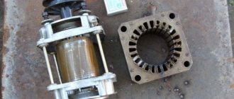
Compound blocks
There are certain rules in our Universe. People discovered this thousands of years ago when they began to distinguish between the force of gravity and the ability of some objects to attract or repel other objects. Then people discovered another set of rules of attraction and repulsion that were completely separate from the first.
People have categorized objects and determined through experimentation that positive and negative are opposite manifestations of a property called charge, just as north and south poles are opposite manifestations of something called magnetism, just as left and right hands are two types hands
Image showing mirror symmetry between electric charges, magnetic poles, and hands
Something happened in Oersted's wire regardless of whether the compass needle was under it or not. This leads to the idea of intangible electromagnetic fields that permeate the Universe - both the densest matter and the vacuum. Each of our objects, categorized as (+/-/N/S), affects the space around it and is affected if the field surrounding it changes.
Horn antenna
A horn antenna consists of an expanding horn-shaped metal waveguide that collects radio waves into a beam. Horn antennas have a very wide range of operating frequencies; they can operate with a 20-fold gap in its boundaries - for example, from 1 to 20 GHz. The gain varies from 10 to 25 dB, and they are often used as feeds for larger antennas.
Radiation scheme
Superposition of waves (superposition principle)
Waves transfer energy from one place to another.
Left untouched for a long period of time, the surface of the pool water will appear flat and still. If you disturb water in one place, water molecules will disturb neighboring water molecules, which will disturb neighboring water molecules, and so on, until the disturbance reaches the edge of the pool.
The molecules that started the chain of events remain in place close to their initial location, but the disturbance will reach the edge of the pool in seconds. Waves transfer energy without transferring matter.
Single wave in the pool
Waves, as we describe them, are the movement of disturbances through a medium. A single initial disturbance or a million such disturbances lead to the propagation of the disturbance by a chain reaction of collisions of molecules in the pool.
Graph of the propagation of two waves in a pool
When two waves disturb the same region of space, their amplitudes will add or subtract, creating either constructive or destructive interference. This practice of temporary addition or subtraction is called the principle of superposition.
Constructive wave interference graph
Once the waves interfere at a particular location, they continue to move in the same direction and at the same speed at which they started for as long as they remain in the same medium. The speed and direction may change as the wave enters a new medium. Sound waves travel through air, water waves travel through liquids—the substances through which the waves travel are called “medium.”
Electromagnetic waves can travel through media such as air and water, or through the void of space - they do not require a medium to propagate energy from one place to another.
Instructions for assembling the best antennas
You can assemble many interesting and effective antennas with your own hands. Let's look at detailed instructions for making the best and easiest to make models.
Homemade #1 - simple TV antenna
If the repeater is located within 30 km from the dacha, then the most common design, assembled from two tubes and a cable, will do. The wire is connected to the corresponding TV input jack.
Layout and selection of materials
A typical device for a primitive country antenna is shown in the figure below. It can be seen that two tubes of the same length are joined on a plate, which in turn is fixed to the mast.
A pipe signal catcher can be made in a couple of hours. The work does not require any qualifications of the performer or the presence of expensive tools
The first thing you need to do is find out the broadcast frequency of the local TV tower - the length of the pipes depends on the parameter.
Broadcast band range – 50-230 MHz. Each channel requires its own length of antenna “whiskers”.
The table shows the design parameters of the signal catcher based on the frequency of the broadcasts. The broadcast band is divided into 12 channels
Pipes made of duralumin, steel, and brass are suitable for making an antenna. Their diameter can vary between 8-24 mm, most often they take 16 mm. The main condition is that the sections must be equivalent, prepared from pipes with the same properties.
Necessary materials:
For work, it is advisable to stock up on a soldering iron, solder, and flux. It is recommended to solder the connections of the central conductors - this will extend the life of the device and improve image quality.
To protect against oxidation, the joint areas must be filled with silicone or epoxy resin. An affordable, but not reliable way is to wrap it with electrical tape.
Assembly and configuration of the invention
First, cut the required size of the pipe and saw it into two equal parts. You can use metal cutters.
The next step is to flatten the tubes on one side for easy attachment to the holder. The pieces are applied to the getinax and fixation points are marked.
The distance between the inner ends of the tubes is 6 cm, between the outer ends - the distance indicated in the table.
Subsequent work progress:
Two people are needed to determine the optimal position of the device. The first rotates the antenna on the street, and the second monitors the change in the image on TV.
To quickly set up, you can check with your neighbors on which side of the house the receiver is located and where the vibrators are directed
Having detected good signal quality, the structure is fixed in the selected position.
Homemade #2 - loop antenna made from pipe
The module is a little more difficult to create, but it expands the reception radius to 40 km. The main difficulty lies in the need to bend the pipe.
The bending radius does not have a special role. The main requirements for the device: the distance between the inner ends is 65-70 mm, the evenness and symmetry of the arrangement of the wings
The length of the cable and pipe is calculated based on the broadcast frequency of TV channels.
Blanks are made to suit the required parameter - the vibrator and the wire for the matching device are measured and cut. The recommended pipe diameter is 12-18 mm.
Table values for the correspondence between channel frequency and signal catcher parameters. For example, with an airwave indicator of 93.25 MHz, the length of the pipe should be 151 cm, and the length of the matching cable should be 104 cm
Assembly begins by bending the pipe. The edge of the vibrator is flattened and sealed. The pipe is filled with sand, and the second end is sealed in the same way as the first. The edges can be sealed by placing the plugs on silicone.
The shaped pipe is attached to the mast. Matching loops are screwed and soldered to the ends of the vibrator, and the television cable is fixed. Secure the braid with copper wire and begin setting up.
Homemade #3 - Kharchenko signal catcher
The figure-of-eight or zigzag television antenna is suitable for DVB-T2 digital television, broadcasting in the UHF range. The module is easy to manufacture. To implement the project, you will need conductive metal.
Calculation and drawing development
The design of the TV antenna is very primitive - two squares/diamonds fastened together. In the original design, the Kharchenko module provides for a reflector located behind the figured elements.
A field of metal strips is required for analog signals. Digital television reception is possible without a reflector. The field can be developed later if the reception is poor
To make a zigzag antenna, it is not necessary to calculate the wavelength. It is advisable to build a structure with more broadband - this will increase its capabilities.
If desired, you can calculate the device parameters. Divide the wave value of the transmitted signal by 4 - the resulting value is the side of the square.
There should be a small distance between the two parts of the TV antenna. To maintain the gap, it is enough to make the outer sides longer and the inner sides shorter. Length of sides (B1 and B2) - at your discretion
The example shown shows a drawing of an antenna with side parameters: B1 - 14 cm, B2 - 13 cm. The difference in lengths of one centimeter gives the required distance between the squares.
The lower sections are extended by 1 cm. This gap is necessary for the loop for soldering the antenna cable.
Frame making and cable preparation
Subsequent calculations will be given in relation to the data in the drawing shown above. The total perimeter of the squares is 112 cm. You should cut the wire to the required length and form the part according to the diagram.
Work order:
Minor differences in side lengths are acceptable. The main thing is to maintain right angles.
If the molding of the structure is done correctly, then between the two parts of the TV antenna there should be a distance of 1.5-2 cm
The next step is preparing the cable. It is cleaned on both sides. An incision is made along the circumference of the cable, 2-2.5 cm from the edge.
The work is done carefully so as not to damage the inner braid. Along the cut line, the cable is slightly broken and the insulation is removed.
The braid and foil must be twisted into a bundle. You should get two conductors: a central monocore and a twist. Both elements must be tinned. The wire should stick out 2 cm, cut off the excess
Solder the plug on the other side of the cable. The wire must be cleaned to 1 cm, the conductors must be formed and tinned.
In areas where soldering is performed, clean the plug with sandpaper and wipe with alcohol. Solder a monocore to the central output, and a twist to the side output. Crimp the grip around the insulation, screw on the plastic tip, or alternatively, fill it with non-conductive sealant. Before the composition dries, assemble the plug.
The order of connecting elements
The final stage of assembly is the joining of the frame and cable. If there is no connection to a specific channel, then it is better to do the soldering at the midpoint to expand signal capture.
The cut end of the cable is connected to the two sides of the square in the center. Before final fixation, you can check the performance of the antenna. If everything is normal, then seal the soldering area.
The most reliable method is to fill it with silicone or glue. A plastic lid from a five-liter eggplant is suitable for the case.
Holes are made in the mini-container for the square elements, a frame with a wire is placed and filled with a sealing compound.
Homemade product #4 – “double square” antenna
The narrowband design will solve the problem of a weak signal or clogging of the broadcast with a stronger broadcast. The antenna is also suitable for receiving digital television. The main condition for operation is a clear orientation towards the signal distributor.
Device diagram and dimensions
Structurally, the TV antenna is presented in the form of two frames connected at the top and bottom by arrows. The large square is a reflector, the smaller one is a vibrator.
A variation with three frames is possible, providing a high signal gain. Least square – director
The upper boom is made of metal, and the lower one is made of getinax, textolite or other insulating material.
Requirements for the TV antenna device:
- the centers of the squares must be on the same line, this straight line faces the transmitter;
- the smaller frame has an open contour, the ends are fixed to the textolite plate;
- The upper part of the mast for the antennas is made of wood.
The parameters for the manufacture of two-element frame television antennas are taken from the table. The dimensions of the working elements depend on the type of waves: decimeter or meter.
Explanations for the table: B – side length of the smaller square, P – value of the larger frame, A – distance between two elements, W – loop in a short-circuited bridge
In a three-frame design, the distance between the ends of the middle frame is increased to 5 cm.
Assembly and connection
To connect the frame to the antenna cable, you will need a balun short-circuited cable. The device is constructed from sections of antenna wire.
The right element is a cable, the shortened left one is a feeder. A television cable is attached to the place where they are connected. The length of the segments is determined from the table, taking into account the wavelength of the signal.
Before assembling the elements, they are cleaned. The aluminum layer is removed from the cable and the braid is twisted into a bundle. The central conductor is cut off
The same actions are performed with the feeder, leaving the cable core.
Further sequence of work:
The use of a matching device reduces the likelihood of interference and eliminates the double image effect. You cannot do without it if you are at a significant distance from the transmitter.
Wave reflection
When waves pass from one medium to another, part of their energy is transferred, part of the energy is reflected, and part of the energy is dissipated into the environment.
The material properties of these two media determine the ratios of transmission to reflection and scattering. And also the properties of materials determine whether the wave will be inverted when reflected.
Transmission and reflection of energy from a single wave pulse A continuous incident wave (orange) hits the boundary of the media, where part of the energy is reflected (light orange) and part of the energy is transmitted (dark orange)
Corner antenna
A type of antenna often used on VHF and UHF transmitters. It consists of an irradiator (this can be a dipole or a Yagi array) mounted in front of two flat rectangular reflective screens connected at an angle, usually 90°. A sheet of metal or a grating (for low-frequency radars) can act as a reflector, reducing weight and increasing wind resistance. Corner antennas have a wide range, and the gain is about 10-15 dB.
Radiation scheme
Reflection and inversion
When waves propagate from one medium to another, some of the incident energy is reflected. Depending on the properties of the media's materials, waves may be inverted upon reflection.
Imagine a long spring tied to a post. If you lightly hit a spring from the left, the disturbance will spread along the entire length of the spring until it hits the post; and at that moment it will change direction and begin to spread back to you on the other side, to the right. This is inversion.
Wave inversion upon reflection
Take the same spring and tie it to a rope looped around a post. If you lightly hit the spring from the left, the disturbance will spread along the entire length of the spring until it hits the rope; at this point it will change direction and begin to spread back towards you from the same side, to the left.
No inversion when reflected
Understanding the reflection of spring vibrations will help us understand what is happening inside the antenna.
Here are four situations to help illustrate the concepts of reflection and inversion.
Whether or not a wave is inverted upon reflection is determined by the properties of the media on both sides of the interface.
If the wave is inverted upon reflection and we want constructive interference in a rope, we must have a rope that is half a wavelength, a full wavelength, or one and a half wavelengths long, and so on:\(L = n {\lambda \over 2} \), where n is a positive integer.
Antenna resonance is based on the same principles of reflection and interference: choose the length of the wire so that the reflected energy can interfere constructively, creating a larger signal rather than reducing it.
Area of application of antennas
The wave range ranges from fractions of a mm to tens of kilometers. This has given rise to a variety of antenna types and many areas of use. Receiving and transmitting devices are used in the following areas:
- wireless connection;
- medicine;
- navigation systems;
- space/aviation mapping technology;
- astronomy;
- radar;
- geology and many others.
Antennas are actively used in radio telescopes for space exploration, in military radar, in chips for continuous measurement of indicators/study/diagnosis of pathologies in the body of people/animals, and just in everyday life.
Modern man cannot imagine life without gadgets, and their control is based on a receiving/transmitting device. The antenna mast is practically not used for domestic purposes, except to increase the reception area of the modem; now the signal is sent to satellite dishes or supplied via mobile and wired Internet, etc.
Standing waves
When two waves of the same length propagate in the same medium but in opposite directions (shown in blue and orange in the examples below), they can interact and form a standing wave (shown in green in the examples below). Standing waves are so called because while blue waves move to the left and orange waves move to the right, green standing waves have no visible movement in either direction.
The incident wave (orange) and reflected wave (blue) combine to form a standing wave (green)
A standing wave occurs only under certain conditions in the medium, which are determined by the mode of reflection and the length of the incident wave.
Television receiving antennas.
Unlike the waves used for AM broadcasting, the waves used for TV broadcasting are much shorter, so half-wavelength receiving antennas are feasible. Thus, a television half-wave symmetrical vibrator is so small that it can be made from a rigid tube. However, the small size of even an electrically long antenna at these frequencies means that the effective reception area of the incident wave (and therefore the antenna's ability to capture its energy) is limited. Additionally, due to the large bandwidth of the television signal and the noise distributed evenly across the channel, the receiver must receive a significant amount of power to provide an acceptable signal-to-noise ratio. In light of the above, it becomes clear that the efficiency of the antenna plays an important role in the reception of a television signal.
At operating frequencies of television broadcasting, atmospheric interference is not of particular importance, but the receiving antenna will pick up a lot of industrial interference and cosmic noise. Therefore, it is important that the receiving antenna has a clearly defined directionality, which allows it not to receive signals coming from directions that do not coincide with the direction of the desired transmitting station. Another type of interference that often degrades the quality of television reception is multipath propagation, in which the desired signal arrives at the receiving antenna along two paths of different lengths. So, for example, one signal can come directly from the transmitter, and another can be reflected from a mountain or building. Multipath propagation appears on the screen in the form of multi-contour images, and to get rid of it, you need to use a directional antenna that allows you to exclude reception along one of the two beams.
The bandwidth of a television receiving antenna must be very large, since it is required to cover not just one channel, but usually all thirteen, located in the 4:1 frequency range. Fortunately, matching the transmission line to the antenna, in which reflections do not occur, is not so important on the receiving side, where the mismatch only leads to the loss of a weak signal without generating echoes. However, the matching of the connecting line to the receiver is important, but in this case attention should be paid to the design of the receiver.
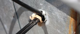
Reflections arising from irregularities in the connecting line can cause multi-edge or loss of image sharpness. These reflections often occur if a two-wire ribbon cable runs too close to metal structures, such as wire trays or drains. This will become clear if we remember that high-frequency electromagnetic energy propagates in a field that arises around the wires that serve as conductors of this field.
One of the simplest antennas used to receive a television signal is the half-wave loop dipole (Fig. 7), which differs from the conventional half-wave dipole in that its output impedance (300 ohms) is consistent with commonly used types of feeders, as well as the that it has a wider band; in other words, it effectively transfers the received electromagnetic energy of a wider range of frequencies into the connecting line.
To obtain the desired radiation pattern in the horizontal and vertical planes, the base antenna is usually used in conjunction with one or more passive elements. A passive element is another antenna located close to the main one, but not connected to the feeder. It is connected to the main antenna (and therefore to the receiver) only by local fields. Understanding how a passive element affects an antenna's radiation pattern is easy because it uses essentially the same principle as an omnidirectional array antenna; the difference is that in this case only one antenna is excited, while the other receives energy only from its near field. As an example, we note that a half-wavelength rod placed (as shown in the figure at a distance of a quarter wavelength from a half-wave dipole) acts as a reflector. Why this is true can be explained as follows. The local field of the excited (main) antenna induces passive element, the charges and currents are of the opposite sign, but due to the distance of a quarter wavelength, these currents and charges lag behind the corresponding currents and charges in the main antenna by approximately a quarter of a period, i.e. the current in the passive element leads the current in the main antenna by approximately 90° The radiation pattern of the driven antenna with a passive element is determined by superimposing both radiated wave fields. This situation is very similar to that considered for an omnidirectional (in the horizontal plane) AM broadcast array, its radiation pattern is shown by the dotted line in Fig. 5. These two waves tend to cancel each other in the direction of the passive element and reinforce each other in the opposite direction; hence the passive element acts as a reflector. The passive element does not have to be a quarter wavelength away from the antenna being excited. If it is placed very close to it, for example at a distance of only 0.1 wavelength, it will still act as a reflector if its length is made slightly more than half the wavelength. Increasing the length of the passive element makes it inductive, as a result of which the current flowing through it lags in phase with the electromotive force induced by the field of the main antenna. If a nearby passive element is made slightly shorter than half the wavelength, it becomes a guide (“director”) and concentrates the radiation on its side of the main antenna. All of the above is directly related to receiving antennas. Since the transmitting and receiving radiation patterns are the same, passive directors and reflectors can be used in television receiving antennas to obtain the required radiation pattern. A typical highly directional antenna array with one reflector and three directors is shown in Fig. 9.
Standing Wave Ratio (SWR)
Standing waves of maximum amplitude occur at a very precise combination of frequency (or wavelength) and antenna length.
Unfortunately, it is impractical and in fact impossible to have antennas that have the exact length required to form an ideal standing wave in the required frequency range. Fortunately, this is not necessary. An antenna with one fixed length can operate over a small frequency range with a small, acceptable level of detuning.
Standing waves and voltages in a line shown during an oscillation period
The antenna length must be adjusted to produce a standing wave as close to ideal as possible at the center of the operating frequency range.
SWR (standing wave ratio) meters measure the ratio of transmitted energy to reflected energy, and this ratio should be as close to 1:1 as possible.
Small adjustments can be made by adding passive components to the circuit between the final gain stage and the antenna. Small deficiencies in antenna tuning can cause a potential difference to appear at the final amplification stage, heating the final section of the transmission line. A large imbalance can cause a large potential difference to be applied back to the transmitter circuit, causing dielectric breakdown, arcing and failure of the final amplifier.
ANTENNA TYPES
The type of antenna design depends on the wavelength at which it must operate. To effectively radiate energy, the antenna must have dimensions close to the operating wavelength. Therefore, at the low frequencies used at one time for transatlantic radiotelegraph and radiotelephone communications (frequencies from 16 to 70 kHz, i.e. waves with a length of 19 to 4.3 km), a huge system of antenna wires with a total length of up to 2 km was electrically short antenna and therefore turned out to be an ineffective radiator. If such an antenna was supposed to have a noticeable directionality, then its efficiency would be very low. On the contrary, at ultrahigh frequencies (microwaves), the use of a half-wave symmetrical vibrator less than 1 cm long and a polished metal reflector with a diameter of only a few centimeters makes it possible to very effectively focus the radiation of such a vibrator into a narrow beam.
Transfer of information
Probably the two most well-known methods of transmitting information are frequency modulation (FM) and amplitude modulation (AM).
Frequency modulation
With frequency modulation, information is transmitted by changing the frequency of the carrier wave.
Frequency modulation
Amplitude modulation
With amplitude modulation, the frequency of the carrier wave remains constant. Information is transmitted by changing the amplitude of the carrier.
Amplitude modulation
Parabolic antenna
One of the most popular radar antennas is the parabolic reflector. The feed is located at the focus of the parabola, and the radar energy is directed to the surface of the reflector. Most often, a horn antenna is used as a feed, but both a dipole and a helical antenna can be used.
Since the point source of energy is at the focus, it is converted into a wavefront of constant phase, making the parabola well suited for use in radar. By changing the size and shape of the reflective surface, beams and radiation patterns of various shapes can be created. The directivity of parabolic antennas is much better than that of a Yagi or dipole; the gain can reach 30-35 dB. Their main drawback is their inability to handle low frequencies due to their size. Another thing is that the irradiator can block part of the signal.
Radiation scheme
Dipole antenna
A simple antenna that uses two identical elements is called a dipole. The shortest dipole antennas operate with oscillations for which the antenna length is equal to half the wavelength, and which creates standing waves along the entire length of the antenna.
Standing waves in a dipole antenna
Varying electric fields along the length of the antenna create radio waves that travel in directions away from the antenna.
Antenna emitting energy
Antennas make it possible to transmit and receive information by interacting with and being affected by the electromagnetic fields that permeate the universe. In the next article we will look at the different types of antennas and how they work.
Original article:
- Mark Hughes. An Introduction to Antenna Basics
Operating principle of the transmitting antenna
Let's consider the principle of operation of the simplest emitting device. If we take a simple two-wire symmetrical line, then it will not radiate into space, despite the fact that high-frequency currents flow in it, Figure 2.
Figure 2 – Two-wire line
There will be no radiation due to the fact that the currents I and I' are in antiphase, which leads them to mutual compensation. To obtain radiation, the ends of a two-wire line can be separated so that the fields from currents I, I' cannot compensate each other, Figure 3.
Figure 3 – Open two-wire line
Such an antenna is called a symmetrical vibrator. The current distribution in the vibrator remains the same as it was in the corresponding section of the two-wire line. To study the field emitted by antennas made of wires, it is convenient to imagine such an antenna in the form of a set of elementary electric vibrators (EEV) of short length (small compared to the wavelength). Within each such elementary vibrator, the amplitude and phase of the current can be considered unchanged. Ultimately, the total field emitted by the antenna can be calculated as the sum of the fields emitted by individual elementary vibrators (in theory, this is called the superposition principle).
In practice, EEV is implemented in the form of a Hertz dipole. This antenna is the first realized emitter of electromagnetic waves, Figure 4.
Figure 4 – Hertz dipole
Such an emitter can be made by installing conducting bodies with high capacitance (for example, metal balls) at the ends of thin wires (length L, less than the wavelength). The charged balls create currents that are significantly higher than the capacitive currents between the wires. This ensures uniform distribution of current along the conductor. Note that in practice the Hertz dipole is practically not used.
Slot antenna
Although the described antennas have fairly high gain relative to the aperture size, they all have common disadvantages: high side-lobe susceptibility (susceptibility to nuisance reflections from the earth's surface and sensitivity to targets with a low effective scattering area), reduced efficiency due to beam blocking (small radars, which can be used on aircraft, have a problem with blocking; large radars, where the problem with blocking is less, cannot be used in the air). As a result, a new antenna design was invented - a slot antenna. It is made in the form of a metal surface, usually flat, in which holes or slots are cut. When it is irradiated at the desired frequency, electromagnetic waves are emitted from each slot - that is, the slots act as individual antennas and form an array. Since the beam coming from each slot is weak, their side lobes are also very small. Slot antennas are characterized by high gain, small side lobes and low weight. They may have no protruding parts, which in some cases is their important advantage (for example, when installed on aircraft).
Radiation scheme
Passive phased array antenna (PPAR) [passive electronically scanned array, PESA]
Radar with MIG-31
Since the early days of creating radars, developers have been haunted by one problem: the balance between accuracy, range and scanning time of the radar. It arises because radars with a narrower beam width increase accuracy (increased resolution) and range at the same power (power concentration). But the smaller the beam width, the longer the radar scans the entire field of view. Moreover, a high-gain radar will require larger antennas, which is inconvenient for fast scanning. To achieve practical accuracy at low frequencies, the radar would require antennas so huge that they would be mechanically difficult to rotate. To solve this problem, a passive phased array antenna was created. It relies not on mechanics, but on the interference of waves to control the beam. If two or more waves of the same type oscillate and meet at one point in space, the total amplitude of the waves adds up in much the same way as waves on water add up. Depending on the phases of these waves, interference can strengthen or weaken them.
The beam can be shaped and controlled electronically by controlling the phase difference of a group of transmitting elements - thus controlling where amplification or attenuation interference occurs. It follows from this that the aircraft radar must have at least two transmitting elements to control the beam from side to side.
Typically, a radar with PFAR consists of 1 feed, one low-interference amplifier, one power distributor, 1000-2000 transmitting elements and an equal number of phase shifters.
Transmitting elements can be isotropic or directional antennas. Some typical types of transmission elements:
On the first generations of fighter aircraft, patch antennas (strip antennas) were most often used because they were the easiest to develop.
Modern active phase arrays use groove emitters due to their wideband capabilities and improved gain:
Regardless of the type of antenna used, increasing the number of radiating elements improves the radar's directivity characteristics.
As we know, for the same radar frequency, increasing the aperture leads to a decrease in beam width, which increases range and accuracy. But for phased arrays, it is not worth increasing the distance between the emitting elements in an attempt to increase the aperture and reduce the cost of the radar. Because if the distance between the elements is greater than the operating frequency, side lobes may appear, significantly degrading the radar's performance.
The most important and expensive part of the PFAR is the phase shifters. Without them, it is impossible to control the signal phase and beam direction.
They come in different types, but generally they can be divided into four types.
Phase shifters with time delay
The simplest type of phase shifters. It takes time for a signal to travel through a transmission line. This delay, equal to the phase shift of the signal, depends on the length of the transmission line, the frequency of the signal, and the phase velocity of the signal in the transmitting material. By switching a signal between two or more transmission lines of a given length, the phase shift can be controlled. Switching elements are mechanical relays, pin diodes, field-effect transistors or microelectromechanical systems. Pin diodes are often used because of their high speed, low loss, and simple bias circuits that provide resistance changes from 10 kΩ to 1 Ω.
Delay, sec = phase shift ° / (360 * frequency, Hz)
Their disadvantage is that the phase error increases with increasing frequency and increases in size with decreasing frequency. Also, the phase change varies with frequency, so they are not applicable for very low and high frequencies.
Reflective/quadrature phase shifter
Typically this is a quadrature coupling device that splits the input signal into two signals 90° out of phase, which are then reflected. They are then combined in phase at the output. This circuit works because signal reflections from conductive lines can be out of phase with respect to the incident signal. The phase shift varies from 0° (open circuit, zero varactor capacitance) to -180° (shorted circuit, infinite varactor capacitance). Such phase shifters have a wide operating range. However, the physical limitations of varactors mean that in practice the phase shift can only reach 160°. But for a larger shift it is possible to combine several such chains.
Vector IQ modulator
Just like a reflex phase shifter, here the signal is split into two outputs with a 90-degree phase shift. The unbiased input phase is called the I-channel, and the quadrature with a 90-degree offset is called the Q-channel. Each signal is then passed through a biphasic modulator capable of shifting the phase of the signal. Each signal is phase shifted by 0° or 180°, allowing any pair of quadrature vectors to be selected. The two signals are then recombined. Since the attenuation of both signals can be controlled, not only the phase but also the amplitude of the output signal is controlled.
Phase shifter on high/low pass filters
It was manufactured to solve the problem of time-delay phase shifters not being able to operate over a large frequency range. It works by switching the signal path between high-pass and low-pass filters. Similar to a time delay phase shifter, but uses filters instead of transmission lines. The high-pass filter consists of a series of inductors and capacitors that provide phase advance. Such a phase shifter provides a constant phase shift in the operating frequency range. It is also much smaller in size than the previous phase shifters listed, which is why it is most often used in radar applications.
To summarize, compared to a conventional reflective antenna, the main advantages of PFAR will be: high scanning speed (increasing the number of tracked targets, reducing the likelihood of the station detecting an radiation warning), optimization of the time spent on the target, high gain and small side lobes (difficult to jam and detect), random scan sequence (harder to jam), ability to use special modulation and detection techniques to extract signal from noise. The main disadvantages are high cost, the inability to scan wider than 60 degrees in width (the field of view of a stationary phase array is 120 degrees, a mechanical radar can expand it to 360).