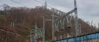
Overhead power transmission towers are an integral part of energy systems that are needed by all types of civil, military, and industrial facilities. In the complex of residential low-rise and high-rise construction, during the construction of industrial facilities, infrastructure is planned and built, which includes power lines, substations and supports. The durability of the power transmission line structure, its strength, and resistance to a number of external mechanical and natural factors depend on the choice of type and type of supports. Reliable supports, in turn, guarantee trouble-free power supply to infrastructure facilities, excluding interruptions and the occurrence of emergency situations. Modern standardized supports allow the construction of reliable overhead power lines in a short time in different climatic zones, on soils of different bearing capacity.
Types and purpose of power transmission line supports
All existing types of structural products that serve as supports perform the function of supporting overhead power line wires. Depending on the line voltage, there are supports designed for 220V, as well as 0.4, 6, 10, 35, 110, 150, 220, 330, 400, 500, 750 and 1150 kV. In this case, air lines are divided into three categories:
- from 0.4 to 10 kV;
- from 35 to 110 kV;
- from 220 to 330 kV.
The distance between the supporting elements of a power transmission line structure is called the span. The higher the operating voltage of a high-voltage line, the longer its crossarms, the larger the dimensions and weight of the structure.
In this case, the design of the support posts must provide the ability to install:
- cable terminations;
- protective switches and devices;
- panels and cabinets for connecting individual electrical receivers;
- switching and sectioning devices;
- street lighting fixtures of any design.
Based on the method of fastening, a distinction is made between supports that can be installed directly on the ground, as well as elements for the installation of which it is necessary to build a special foundation. The latter are divided into classic and narrowly basic. In its usual form, the width of the mounting base has an area of more than 4 m2, providing for frame, frame or poured foundations. The narrow base category includes all bases whose area is less than 4 m2. Often such fastenings involve the installation of a reinforced concrete or screw pile, a steel pipe and are used in areas with limited space.
Depending on the type of fastening, the supports can be differentiated into upright and guyed structures. The latter are the most stable and durable, requiring additional work on the installation of guys and their fastening, each of which must have its own separately formed foundation.
Intermediate straight supports.
They are calculated on the following conditions. The calculation of intermediate corner supports for emergency mode is carried out for the same loads as the calculation of intermediate straight supports (see § 1-5). In this case, it is necessary to consider the most unfavorable of the two cases corresponding to the limiting values of the angle of rotation for which this support is calculated. At the smallest angle of rotation of the line, the unbalanced component of the tension of the unbroken wire, perpendicular to the traverse, Sncos α/2 reaches its maximum value (at a = 0, Sncosα/2=Sp) and the greatest torque acts on the support. At the greatest angle of rotation, the component Sncos α/2 decreases, but the component Snsin α/2 increases, as well as the components 2Tsina/2 at the points of attachment of the garlands of all other wires and cables. Obviously, for the face of the steel support trunk perpendicular to the axis of the crossbeam, the first case will be calculated, and for the face parallel to the axis of the crossbeam, as a rule, the second (at the largest value of angle a). The tension in unbroken wires T, depending on the load and temperature, is determined from the mechanical calculation of the wire under the corresponding modes.
Metal, reinforced concrete, wood and composite supports - advantages and disadvantages
Depending on the material used, supports are made of:
- wood;
- reinforced concrete;
- become.
Currently, there are also composite type supports that include elements from various materials. For example, reinforced concrete can be assembled with metal tips, ribs, and posts to form the required configuration and size.
Each type of support elements has a set of individual characteristics that must be taken into account when designing and installing on site.
Reinforced concrete supports are made of concrete, which is reinforced with metal to enhance strength. In order to increase reliability for lines from 35 to 110 kV, centrifugation technology is used during production, with the help of which the concrete mixture is compacted as much as possible, eliminating air layers that reduce strength. During the production process, the solution is poured into special metal molds, inside of which there is a pre-created reinforced frame of transverse and longitudinal rods. Reinforced concrete products are resistant to external influences and corrosion. The chemical inertness of concrete does not allow it to interact with chemical elements, allowing operation in aggressive environments and reagents with which the air can be saturated. One of the main disadvantages of such supports is their high weight, which makes delivery difficult and places demands on the installation process and the quality of the prepared base. At the same time, reinforced concrete is characterized by a high degree of durability, which guarantees trouble-free operation of supports over a long service life, which is at least 60 - 80 years.
Wooden poles for power lines are made from solid logs. Most often, their use is relevant for low-voltage overhead lines with a voltage of 220 or 380 V. The material used in the production of supports is predominantly coniferous wood, less often deciduous. One of the main advantages of using wooden wire fastening elements is its affordable cost. in the presence of local types of wood, this allows for significant savings in the construction and laying of power lines. At the same time, such supports are inferior in durability to metal, reinforced concrete and composite products. During operation, wood is destroyed under the influence of sunlight, moisture, the parasitic influence of insects, due to seasonal temperature changes and other natural factors. In order to increase their service life, wooden logs are treated with special compounds. Mastics and resins can extend the durability of products to 20–25 years in the most favorable conditions. Wooden supports are used for the construction of A- and U-shaped structures.
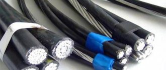
Metal support products for power lines are made from steel alloys of established grades. Separate structural components, representing load-bearing elements and stiffeners in the form of beams and corners, are connected together. For this purpose, a welded rigid connection is used, which provides connection of surfaces at the molecular level or a prefabricated connection using bolts and nuts. In order to prevent a decrease in the strength of metal supports due to corrosion, galvanized rolled steel is often used. Some structures are painted with special protective compounds. Depending on the design features, the following types of steel supports are distinguished:
- lattice;
- multifaceted.
In addition, support structures made from closed and open profiles are distinguished. The former include hexagons and octahedrons, the latter triangles and products with a square section. Also, pipes are often used as a basis for the construction of steel supports for power lines.
Composite types of supporting elements are a new type of structures that incorporate individual units made of various materials.
Overhead power lines. Support structures.
Rice. 2. Cycle of transposition of single-circuit line wires
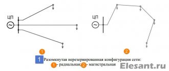
Depending on the number of chains suspended on the supports, the supports can be single-chain or double-chain
.
a reverse Christmas tree
or
on double-circuit supports .
The most common locations of wires on supports are shown schematically in Fig. 3.
Rice. 3. The most common locations of wires and cables on supports
:
a – location along the vertices of the triangle; b - horizontal arrangement; c – reverse tree arrangement
The possible location of lightning protection cables is also indicated there. The arrangement of wires along the vertices of the triangle (Fig. 3, a) is widespread on lines up to 20-35 kV and on lines with metal and reinforced concrete supports with a voltage of 35-330 kV.
The horizontal arrangement of wires is used on 35 kV and 110 kV lines on wooden supports and on higher voltage lines on other supports. For double-chain supports, it is more convenient from an installation point of view to arrange the wires in a “reverse tree” type, but it increases the weight of the supports and requires the suspension of two protective cables.
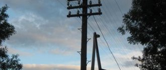
Wooden supports
were widely used on overhead power lines up to 110 kV inclusive. The most common are pine supports and somewhat less common are larch supports. The advantages of these supports are their low cost (if local wood is available) and ease of manufacture. The main disadvantage is wood rotting, especially intense at the point of contact of the support with the soil.
Metal supports
made of special grades of steel for lines of 35 kV and above, they require a large amount of metal.
Individual elements are connected by welding or bolts. To prevent oxidation and corrosion, the surface of metal supports is galvanized or periodically painted with special paints. However, they have high mechanical strength and a long service life. Install metal supports on reinforced concrete foundations. These supports, according to the design of the support body, can be classified into two main schemes - tower
or
single-column
, Fig.
4, and portal
, fig.
5.a, according to the method of fastening to foundations - to free-standing
supports, Fig.
4 and 6, and supports on guy wires
, Fig. 5.a, b, c.
On metal supports with a height of 50 m or more, stairs with guardrails reaching the top of the support must be installed. In this case, each section of supports must have platforms with fences.
Rice. 4. Intermediate metal support of a single-circuit line
:
1 – wires; 2 – insulators; 3 – lightning protection cable; 4 – cable support; 5 – support traverses; 6 – support stand; 7 – support foundation
Rice. 5. Metal supports
:
a) – intermediate single-circuit on guy wires 500 kV;
b) – intermediate V -shaped 1150 kV; c) – intermediate support of 1500 kV DC overhead line; d) – elements of spatial lattice structures
Rice. 6. Metal free-standing double-chain supports
:
a) – intermediate 220 kV; b) – anchor corner 110 kV
Reinforced concrete supports
are carried out for lines of all voltages up to 500 kV. To ensure the required density of concrete, vibration compaction and centrifugation are used. Vibration compaction is carried out using various vibrators. Centrifugation provides very good compaction of concrete and requires special machines - centrifuges. On overhead power lines of 110 kV and above, the support posts and traverses of the portal supports are centrifuged pipes, conical or cylindrical. Reinforced concrete supports are more durable than wooden ones, there is no corrosion of parts, they are easy to operate and therefore are widely used. They have a lower cost, but have greater mass and relative fragility of the concrete surface, Fig. 7.
Rice. 7. Intermediate reinforced concrete free-standing single-chain
supports
:
a) – with pin insulators 6-10 kV;
b) – 35 kV; c) – 110 kV; d) – 220 kV
Crossbeams of single-column reinforced concrete supports are galvanized metal.
The service life of reinforced concrete and metal galvanized or periodically painted supports is long and reaches 50 years or more.
Marking and designation
To designate power line supports, letter markings are used, which allows each structure to be assigned a separate name: For steel, composite and reinforced concrete types of supports designed for laying overhead lines with an operating voltage value from 35 to 330 kV, the following designations are accepted:
- “A” - anchor products;
- “US”, “U” and “AU” - designation of anchor-angle type products;
- “PS” and “P” are intermediate structures;
- “PUS” and “PU” - angular intermediate elements;
- “PVS” - intermediate supports with internal connections;
- “B” - reinforced concrete products (with the exception of supports designed for 500 kV);
- “KS” and “K” - end-type products;
- “PC” - composite intermediate support structures;
- "PP" - transitional intermediate products.
The digital index, which is given after the letter designation, reflects the voltage class. The presence of a letter indicator with the letter “t” indicates the presence of a cable stand with 2 cables. If the letter “p” is given, then the product provides for a change in the relative position of the conductors in the support structure. In most products, to achieve this goal, the wires are transferred to the adjacent tier, where the necessary sequence is formed.
The number indicated with a hyphen determines the number of circuits: if the value is odd, then the line is positioned as single-circuit, the even value belongs to multi-chain structures. In addition, the number may indicate the type of product. Additionally, some elements may indicate a digital value with a “+” sign, which reflects the height of the attachment to the base support. This value applies exclusively to supports made of steel.
Classification of supports by functional purpose
According to their design and technological purpose, power transmission line supports are divided into the following types:
- intermediate – the most popular and widely demanded type of product, which is designed to maintain conductors at the design height. When designing and building high-voltage lines, intermediate support elements make up 80–90% of the total number of products used. In this case, the intermediate supports are intended solely to support the wires and do not bear the load from the tension of the wires. The amount of permissible load depends on the model of the supporting elements, which are accepted for installation during individual calculations. Installation of intermediate supports is carried out on straight sections of the line. Steel and reinforced concrete products can be used at low temperatures of negative temperatures down to – 65 ºС, allowing the use of elements in the northern regions of the country;
- transitional or anchor - are used at points, network nodes, where the presence of barriers of natural origin or engineering structures requires a change in topology. These may include reservoirs, rivers, ravines, hills, infrastructure facilities, etc. The supports have increased dimensions, which allow them to withstand significant loads caused by the tension of the wires. The design of such products is characterized by increased rigidity;
- corner – products which are installed at the turning points of the high-voltage line. Angular intermediate elements are used for small rotation angles - up to 30 degrees. Above that, full-fledged corner anchor structures of supporting products are used, allowing them to withstand the forces of constant tension of wires and cables of adjacent spans;
- end - products, the installation of which is carried out at the starting and ending points according to the power line installation project. The wires from them go to the substation portals. Elements of this type, as a rule, perceive a one-sided load from the tension of the conductors;
- transpositional - supports of a special type, which are used if there is a need to organize branches or change the order of conductors running as part of an overhead line. Also, special products are used in cases where the line needs to be strengthened to increase the anti-wind load or when two or more cross power lines intersect.
Intermediate supports
Where are they used?
: on straight sections of the road strictly between two anchor supports.
Intermediate supports (designated “P”) - do not take part in tensioning the wires, but only support them. Of all the supports on the route, 85% are intermediate.
Under normal operating conditions, they experience loads only vertically and horizontally. The design of this type of support is not as rigid as in “A”. However, intermediate supports must have a certain margin of safety, since in unforeseen situations the load on them can greatly increase. In emergency mode, the intermediate support must withstand the break of two cables or wires.
When hanging overhead lines on intermediate supports, supporting garlands of insulators are used.
Advantages of reinforced concrete supports
One of the most popular and in demand these days are reinforced concrete power line supports. Representing one of the most practical and cost-effective types for the construction of power lines, reinforced concrete structures have a number of advantages, including:
- long service life. The durability of reinforced concrete is 50-70 years, depending on operating conditions;
- resistance to external influences such as moisture, direct sunlight, etc.;
- environmentally friendly material that does not emit toxins and does not harm the environment;
- resistance to corrosion processes;
- high mechanical strength, which is achieved through concrete reinforcement;
- affordable price;
- minimum requirements for the installation and assembly process;
- wide operating temperature range - from -55 to + 55°C;
- high fire safety of a material that is not flammable;
Along with the advantages, reinforced concrete supports have only one drawback, which comes down to their large mass. Despite this, the use of products is justifiably considered cost-effective and effective for various networks and overhead lines that are designed to ensure trouble-free and uninterrupted power supply.
Types and technology of manufacturing reinforced concrete supports
Reinforced concrete foundations have a reinforced structure. For their manufacture, welded steel frames are used. During the manufacturing process, reinforced bars of both stressed and unstressed structures are placed in the workpieces. After this, the workpiece is filled with concrete mortar. Depending on the technological process used, supports are divided into the following categories:
- SV – vibrating racks for lines with voltage up to 35 kV, which are manufactured using the vibration compaction method, which is used to obtain a homogeneous structure of the material and eliminate air gaps;
- SK, SCP and STs are centrifuged racks designed for power lines with an operating voltage of more than 35 kV. During their manufacture, the mold with poured concrete is subject to rotation. The strength of centrifuged products makes it possible to reduce the cost of constructing overhead lines by increasing the distances between the installed supports.
If our dear reader is interested in where to buy fiberglass fuel containers, we can recommend. A professional company from which you can purchase fuel containers and tanks in which you can store diesel fuel, flammable lubricants and much more. These fiberglass containers are suitable for various products.