Good day to all! In the last article, I talked about anti-aliasing filter chokes and outlined the principle of their calculation. However, these types of chokes are not used very often in household appliances, since in low-power devices it is often more effective to use capacitive filters. The most common type of chokes used in electronic devices is AC chokes. Their features, operating principles and calculation of the parameters of such chokes will be discussed in this article.
To assemble a radio-electronic device, you can pre-make a DIY KIT kit using the link.
Features of the AC choke
An AC choke, just like any other choke, is an inductor with a ferromagnetic core. This type of inductor is connected in series with the load, similar to a smoothing inductor, but unlike it, the current flowing through the AC inductor does not have a DC bias current. In this regard, the AC inductor is widely used in ballast and current-limiting circuits, powerful antenna and filter devices, as well as in various pulse voltage converters.
Regardless of the use of the inductor in the circuit, its operation is based on the dependence of its reactance XL on the frequency f of the current IH flowing through it and the voltage drop across the inductor UL
AC choke.
Thus, the voltage across the inductor UL is determined by the inductance of the inductor L and the parameters of the current flowing through the inductor: the frequency of the current f and the value of the current in the circuit IH.
How does the throttle work?
In AC circuits, to limit the load current, chokes - inductive reactors. Here, chokes have serious advantages over conventional resistors - significant energy savings and the absence of strong heating.
What is the design of the throttle, what is the principle of its operation based on? The structure of the inductor is very simple - it is a coil of electrical wire wound on a core made of ferromagnetic material . The prefix ferro indicates the presence of iron in its composition (ferrum is the Latin name for iron), in one quantity or another.
The principle of operation of the inductor is based on a property inherent not only to coils but also to any conductors in general - inductance. This phenomenon is most easily understood by performing a simple experiment. To do this, you need to assemble a simple electrical circuit consisting of a low-voltage direct current source (battery), a small incandescent light bulb at the appropriate voltage and a sufficiently powerful inductor (you can take the inductor from a 400-watt DRL lamp). Without a choke, the circuit will work as usual - the circuit closes, the lamp lights up. But if you add a choke, connecting it in series with the load (light bulb), the picture will change somewhat. Taking a closer look, you can see that, firstly, the lamp does not light up immediately, but with some delay, and secondly, when the circuit is opened, a clearly visible spark appears, which has not been observed before. This happens because, at the moment of switching on, the current in the circuit does not increase immediately - the inductor prevents this, absorbing electricity for some time and storing it in the form of an electromagnetic field . This ability is called inductance.
The larger the inductance value , the more energy the inductor can store. The unit of inductance is 1 Henry. At the moment the circuit breaks, the stored energy is released, and the voltage can exceed the E.M.F. of the source used tens of times, and the current is directed in the opposite direction. Hence the noticeable sparking at the rupture site. This phenomenon is called E.M.F. self-induction.
If you install an AC source instead of a DC one, using, for example, a step-down transformer , you may find that the same light bulb connected through an inductor does not light up at all. The inductor provides much greater resistance to alternating current than to direct current. This occurs due to the fact that the half-cycle current lags behind the voltage.
Graphically it looks like this.
It turns out that the effective voltage across the load drops many times (and the current accordingly), but energy is not lost - it is returned through self-induction back into the circuit. The resistance provided by inductance to alternating current is called reactive . Its value depends on the magnitude of the inductance and the frequency of the alternating current. The amount of inductance, in turn, depends on the number of turns of the coil and the properties of the core material, called magnetic permeability , as well as its shape.
Magnetic permeability is a number showing how many times the inductance of a coil is greater with a core made of a given material than without it (ideally in a vacuum.) That is, the magnetic permeability of a vacuum is taken as one.
In low-inductance RF coils, rod-shaped cores are used for precise tuning. The materials for them can be ferrites with a relatively low magnetic permeability, sometimes non-magnetic materials with a permeability less than 1. In relay electromagnets there are horseshoe-shaped and cylindrical cores made of special steels.
To wind chokes and transformers, closed cores—magnetic cores Ш—shaped and toroidal are used. The material at frequencies up to 1000 Hz is special steel, above 1000 Hz - various ferroalloys. Magnetic cores are assembled from individual plates coated with varnish.
A coil wound on a core, in addition to reactive (Xl), also has active resistance (R). Thus, the total resistance of the inductor is equal to the sum of the active and reactive components.
Effect of non-magnetic gap on the throttle
In previous articles, I talked about the negative effect of core saturation on reducing the magnetic permeability μe and inductor inductance L, which lead to a distortion of the shape of the current flowing through the inductor.
The shape of the current flowing through the inductor: for an unsaturated core (1) and for a saturated core (2).
This figure shows the distortion of the sinusoidal voltage current shape when the inductor operates in the saturated and unsaturated sections of the magnetization curve. The degree of distortion of the voltage waveform also depends on the ratio of the inductor reactance to the active load resistance XL/RH. That is, when the core is saturated, the lower this ratio, the lower the degree of voltage waveform distortion. Thus, the introduction of a non-magnetic gap, in addition to stabilizing the inductance value, within a wide range of current changes, allows alternating current to pass through the inductor without significant changes.
In addition to the factors described above, the introduction of a non-magnetic gap leads to some features that must be taken into account when developing and manufacturing chokes with a gap. The main feature is the broadening of the magnetic flux in the gap.
Broadening of the magnetic flux in the non-magnetic choke gap: the choke rod (left) and its cross section (right). The dotted line indicates the dimensions of the increased cross-section due to bulging of the magnetic flux.
This phenomenon is due to the fact that in a choke with a gap, the magnetic flux goes beyond the space between the two ends of the cut core, so the cross-sectional area in the non-magnetic gap seems to increase.
The dimensions of the cross-sectional broadening depend on the length of the inductor winding lob, the cross-sectional area of the core Se and the length of the non-magnetic gap lз. Broadening the magnetic flux reduces the magnetic resistance of the circuit and, therefore, increases the inductance of the inductor. To take into account the broadening of the magnetic flux and the increase in inductance, a buckling coefficient F is introduced, which takes into account the broadening of the magnetic flux in the non-magnetic gap. Therefore, the value of the inductor inductance will be determined by the following expression
where ω is the number of turns of wire in the winding,
μ0 – magnetic constant, μ0 = 4π*10-7 H/m,
μе – equivalent (relative) magnetic permeability of the core,
Sе – equivalent cross-sectional area of the core,
lе – equivalent length of the magnetic line of the core.
lM – length of the magnetic line in the core.
F is a coefficient that takes into account the broadening of the magnetic flux in the gap.
Power smoothing filter chokes
The main parameters of power smoothing filter chokes are inductance, rated bias current, DC resistance, and permissible AC voltage. In many cases, with given overall dimensions and weight, they strive to obtain the highest possible (or specified) inductance with minimal resistance to direct current. Since the inductance of the inductor depends on the bias current and the amplitude of the alternating voltage, it is measured at the rated bias current and a given alternating voltage. Calculation of rectifier filter chokes can be performed using the methodology used for calculating matching transformers with constant bias.
Back to the main page … | |
Principles for calculating AC chokes
The calculation of the AC choke is carried out similarly to the calculation of the smoothing choke, but taking into account the initial conditions. So for an AC inductor, the determining parameters are: the required inductance L, the applied voltage UL, the AC frequency f, the overheating of the inductor. In addition, it is necessary to determine the material of the inductor core, which will determine the saturation induction BS and the maximum induction in the core Bm, which, to prevent saturation of the core, is selected from the condition
Calculations of an AC inductor are based on expressions for determining the magnitude of the effective voltage dropped across the inductor UL
where f is the frequency of alternating current,
L – inductance of the inductor,
I – effective value of the inductor current.
Then, taking into account the expression for the inductance of a closed-core inductor and the expression for the maximum inductance in the core, the voltage on the inductor will depend on the following parameters
where μе is the equivalent magnetic permeability of the core,
μ0 – magnetic constant, μ0 = 4π•10-7 H/m,
ω – number of turns of the inductor winding,
Se – equivalent cross-section of the inductor core,
le is the equivalent length of the magnetic path of the inductor core,
Bm – maximum value of core magnetic induction,
ka is the current (voltage) amplitude coefficient of the inductor.
The resulting expression can often be found under the name of the basic formula of transformer EMF, since it establishes a unique relationship between the EMF at the winding terminals and the number of turns of the winding, for a given value of magnetic induction in the core. Then, with a sinusoidal voltage (amplitude factor ka ≈ 1.414), the expression takes the following form
Let's return to the original expression for the voltage on the inductor UL, in which the parameter - the number of turns - is ambiguous. This parameter, among other things (the magnitude of inductance L and magnetic permeability μe of the core) depends on the dimensions of the magnetic circuit, and more specifically on the area of the window SO, which can be calculated using the following expression
where I is the effective value of the inductor current,
ω – number of turns of the inductor winding,
kI – core window utilization factor,
j is the current density in the winding wire.
The parameters kI and j are chosen in the same way as for the smoothing filter choke, that is, the core window utilization factor kI ≈ 0.3, and the current density j = 5 A/mm2.
Then, expressing from this expression the number of turns of wire ω, we obtain
The resulting expression determines the main calculation expression for determining the standard size of the core - the product of the areas of the SeSO core. After transforming the expression for the effective voltage on the inductor UL, we determine the number of turns of the winding ω and the value of the non-magnetic gap δ
where μе is the equivalent magnetic permeability of the core,
μ0 – magnetic constant, μ0 = 4π•10-7 H/m,
Se – equivalent cross-section of the inductor core,
le is the equivalent length of the magnetic path of the inductor core,
Bm – maximum value of core magnetic induction,
ka is the current (voltage) amplitude coefficient of the inductor.
The calculated number of turns is approximate, since due to the broadening of the magnetic flux, the inductance value turns out to be slightly larger for a given number of turns, which in some cases is undesirable. Therefore, it is necessary to recalculate the turns taking into account the magnetic flux broadening coefficient F
It remains to select the cross-section of the winding wire SP
where SO is the window area of the core used,
kI – core window utilization factor,
ω – number of turns of the inductor winding.
The choice of wire cross-section must be made by rounding the resulting value to the nearest nominal value, while it must be taken into account that at high frequencies power losses in the wire increase. Therefore, at a sufficiently high frequency, it is necessary to use a winding wire consisting of several cores, and the core diameter is selected based on the skin depth δ
where f is the frequency of the alternating current flowing through the inductor,
δ – skin layer thickness,
dп – diameter of the core in the winding wire.
After constructive calculation of the core and winding, it is necessary to check the thermal operating conditions of the inductor - heating and overheating of the inductor.
How does a transformer work?
Let's consider the operation of a choke assembled on a closed magnetic circuit and connected as a load to an alternating current source. The number of turns and the magnetic permeability of the core are selected in such a way that its reactance is high, but the current flowing in the circuit is correspondingly not.
The current, periodically changing its direction, will excite an electromagnetic field in the winding of the coil (let's call it coil number 1), the direction of which will also periodically change - reversing the magnetization of the core. If an additional coil is placed on the same core (let’s call it number 2), then under the influence of the alternating electromagnetic field of the core, an induced variable E.M.F. will appear in it.
If the number of turns of both coils is the same, then the value of the induced E.M.F. very close to the value of the voltage of the power source applied to coil number 1. If the number of turns of coil number 2 is halved, then the value of the induced E.M.F. will decrease by half, if the number of turns is the opposite, increase - the induced E.M.F. will also increase. It turns out that for each turn there is a certain part of the voltage.
The winding of the coil to which the supply voltage is applied (number 1) is called primary , and the winding from which the transformed voltage is removed is called secondary .
The ratio of the number of turns of the secondary (Np) and primary (Ns) windings is equal to the ratio of their corresponding voltages - Up (primary winding voltage) and Us (secondary winding voltage).
Thus, a device consisting of a closed magnetic circuit and two windings in an alternating current circuit can be used to change the supply voltage - transformation.
Accordingly, it is called a transformer .
If you connect any load to the secondary winding, a current (Is) will arise in it. This will cause a proportional increase in current (Ip) in the primary winding. The following ratio will be correct:
Transformers can be used both to convert the supply voltage and to decouple and match amplification stages. When working with transformers, it is necessary to pay attention to a number of important parameters, such as: 1. Permissible currents and voltages for the primary and secondary windings. 2. The maximum power of the transformer is the power that can be transmitted through it for a long time without causing overheating of the windings. 3. Operating frequency range of the transformer.
Basic concepts in electronics
The English physicist William Gilbert is considered the founder of the discovery of electricity. In 1600, he introduced the concept of “amber”, which means electricity. Scientists discovered through experiments with amber that if it is rubbed against silk, it acquires the properties of attracting other physical bodies to itself. This is how static electricity was discovered. The first electric car was created by the German engineer Otto von Guericke. The unit looked like a metal pole with a sulfur ball placed on its top.
In subsequent years, a number of physicists and engineers from various countries explored the properties of electricity, discovering new phenomena and inventing instruments. The most outstanding scientists who made significant contributions to science are Galvani, Volt, Estred, Ohm, Faraday, Hertz, Ampere. Recognizing the importance of their discoveries, fundamental quantities characterizing various electrical phenomena were named after them.
The result of their experiments and theoretical guesses was the work of Maxwell, who created the theory of electromagnetic phenomena in 1873. And twenty years later, the Englishman Thomson discovered a particle involved in the formation of electricity (electron), the position of which in the atomic structure of the body was later indicated by Rutherford.
Thus, it was discovered that electric charge is the ability of physical bodies to create a special field around themselves that affects other substances. Electricity is associated with magnetism, which affects the position of electrons, which are the elementary particles of the body. Each such particle has a certain energy (potential) and can move around the body randomly.
Giving electrons directional movement leads to the generation of current. The work spent on moving an elementary particle is called stress. If current flows in a closed circuit, then it creates a magnetic field, that is, a force acting on electrons.
All substances are divided into three types:
- conductors are bodies that freely pass current through themselves;
- dielectrics - the appearance of free electrons in these bodies is impossible, which means that current cannot flow through them;
- semiconductors are materials whose ability to transmit current depends on external factors, such as temperature.
The characteristic indicating the ability of a body to conduct current is called conductivity, and its inverse value is called resistance.
Active resistance
The passage of electric current is ultimately influenced by three physical quantities: resistance, inductance and capacitance. Each radio element (the choke is no exception) possesses them to some extent.
Active resistance is a value that prevents the passage of current and is equal to the ratio of the potential difference to the current strength (Ohm's law). Its essence is explained by the fact that the crystal lattice of different physical bodies contains a different number of free charge carriers. In addition, the structure itself may be heterogeneous, that is, contain impurities or defects. Electrons, moving under the influence of the field, collide with them and give part of their energy to the crystals of the body.
As a result of such collisions, the particles lose momentum and the current strength decreases. The dissipated electrical energy is converted into heat. An element that uses the natural properties of a physical body is a resistor.
As for the inductor, its active resistance is considered parasitic, causing heating and deterioration of parameters. It depends on the type of material and its physical dimensions.
Determined by the formula R = p * L / S, Ohm, where:
- p—resistivity (reference value), Ohm*cm;
- L—conductor length, cm;
- S—cross-sectional area, cm2.
Capacitive component
Any current conductor has the ability to accumulate electrical charge to varying degrees. This ability is called element capacity. For some radio components it is considered a harmful component (in particular, for the inductor), while for others it is considered useful (capacitor). This concept is referred to as reactance. Its value depends on the type of signal supplied to the element and the capacity of the material from which it is made.
You might be interested in: Electrician safety precautions when working with electricity
Mathematically, reactance is described by the expression Xc = 1/w*C, where:
- w is the cyclic frequency, a scalar angular value determined by the number of signal oscillations per unit time (2*p*f), Hz;
- C—element capacity, F.
From the formula it is clear that the greater the capacitance and frequency of the current, the higher the resistance of the element, which means that the inductor, which has a large capacitive reactance, will heat up. The value of the capacitance in the inductor depends on the size of the conductor and the method of its installation. With spiral winding, a capacitance appears between adjacent rings, which also affects the flowing current.
The parasitic component of the capacitance also manifests itself in the formation of the product’s own resonance, since the inductor in the equivalent circuit can be represented as a series chain of inductance and capacitor. This inclusion creates an oscillatory circuit operating at a certain frequency. If the signal frequency is below the resonant value, then the inductive component will dominate, and if higher, the capacitive component will dominate.
Therefore, an essential task of manufacturing a choke in electronics is considered to be to increase the structure’s own resonance.
Inductance and self-induction
The electric field is inextricably linked with the magnetic field. Where one exists, the second invariably appears. Inductance is a physical quantity characterized by the accumulation of energy, but unlike capacitance, this energy is magnetic. Its value depends on the magnetic flux formed by the strength of the current flowing through the radio element. The higher the current, the stronger the magnetic flux penetrates the product. The intensity of energy accumulation by an element depends on this flow.
The mathematical formula for finding inductance is L = Ф/ I, where:
- F—magnetic flux, Wb;
- I is the current flowing through the element, A.
Inductance is measured in henry (H). Thus, the inductor at the moment of current flowing through it creates a magnetic flux equal to one weber (Wb).
The resistance provided by inductance depends largely on the frequency of the applied signal. To calculate it, use the expression XL = w*L. That is, for direct current it is zero, and for alternating current it depends on its frequency. In other words, for a high-frequency signal the element will have high resistance.
The physical process observed when alternating current passes through inductance can be described as follows: during the first decade of the signal (the current increases), the magnetic field intensively consumes energy from the electrical circuit, and in the last decade (the current decreases) it gives it back, so during the period of passage current no power is consumed.
But this model fits an ideal element; in fact, some of the energy is converted into heat. That is, losses occur, characterized by the quality factor Q, determined by the ratio of the received energy to the transmitted one.
When the current flowing through a conductor in a circuit changes, an electromotive force of induction (EDSI) occurs - self-induction. In other words, alternating current changes the magnitude of the magnetic flux, which ultimately leads to the appearance of EDSI. This effect manifests itself in slowing down the processes of current appearance and decay. The amplitude of self-induction is proportional to the magnitude of the current, the frequency of the signal and the inductance. Its phase lag from the signal is 90 degrees.
How to calculate the interturn capacitance of the inductor winding?
In the inductor, between the turns, layers and metal objects around the inductor, there is some potential difference that creates an electric field. To assess the influence of this field, the concept of interturn capacitance or the inductor’s own capacitance is introduced, the value of which depends on the size and design features of the inductor.
The interturn capacitance C of the winding, being a parasitic parameter, together with the leakage inductance and the inductor’s own inductance form various types of filters and oscillatory circuits. Although this parameter is of small importance, nevertheless, in certain conditions it has to be taken into account, but accurate calculation is difficult due to the large influence of various design parameters, primarily, the relative position of the turns of the wire among themselves. So, bulk-wound coils have the greatest interturn capacitance, and coils with “Universal” type winding or sectional coils have the smallest.
The interturn capacitance Cc of the inductor can be represented as the sum of the capacitances between the inner layer of the winding and the magnetic circuit C1 and the interlayer capacitance inside the winding C2
The capacitance between the inner layer of the winding and the magnetic core can be determined from the empirical formula
where εа is the absolute dielectric constant of the medium around the conductor, εа = ε0εr,
εr – relative dielectric constant,
ε0 – electrical constant, ε0 = 8.85 * 10-12 F/m,
r – radius of the cross section of the wire,
a is the distance between the magnetic core and the axis of the wire,
n – number of turns in the layer,
р1 – perimeter of the turn of the inner layer of the winding.
The relative dielectric constant is taken for the material of the inductor frame; if the design is frameless, then, accordingly, the permeability of air or conductor insulation, depending on the required accuracy.
The capacitance between the winding layers is also calculated using the empirical formula
where рср is the perimeter of the middle turn of the winding,
b – distance between the axes of turns in adjacent layers,
m – number of layers.
In this case, the dielectric constant is taken for the interlayer insulation material.
In all cases, it is necessary to reduce the interturn capacitance of the winding. For this purpose, various types of windings and materials for frames and interlayer insulation with a low dielectric constant are used.
Types and characteristics
The main characteristic of the inductor is, of course, inductance. But, besides this, there are a number of nominal parameters that characterize the element as a product. They determine the possibilities of using the device and its service life. The main ones are:
- Power - determined by the type of core and cross-section of the wire. Indicates the magnitude of the signal that the inductor can withstand. The unit of measurement is the watt.
- Quality factor and loss angle characterize the quality of the device. The higher the quality factor and the smaller the angle, the higher the quality.
- Current frequency - f, Hz. Depending on it, chokes are divided into low-frequency, having oscillation limits of 20-20,000 Hz, ultrasonic - from 20 to 100 kHz, and ultra-high - more than 100 kHz.
- The highest permissible current value is I, A.
- The resistance of the element in the unconnected state is R, Ohm.
- Losses in the magnetic circuit - P, W.
- Weight - G, kg.
Modern industry produces electromagnetic chokes that differ not only in characteristics, but also in types. They are available in cylindrical, square, rectangular and round shapes. They also differ in the type of circuit for which they are intended, and can be single-phase or three-phase.
Conventionally, chokes can be divided into three types:
- Smoothing. They are used to filter the variable component of the signal, reducing its value. Such elements are placed at the input or output of rectifying or converting parts of circuits.
- Alternating current. Limit its value during a sharp jump.
- Saturation. Inductive reactance is controlled by periodic magnetization.
Anode choke of the output stage of a low-power AM radio broadcast transmitter.
Well, I love radio tubes... Sergey Komarov (UA3ALW)When operating the output stages of transmitters with a parallel circuit for switching on the circuit and supplying power to the anode circuit, it often happens that the anode chokes heat up and burn. Dozens of anode choke designs have been published, but not a single article contains clear recommendations for designing chokes for AEM transmitters in the 200 m range. Since broadcast transmitters operate continuously for many hours without turning off, designing a reliable anode choke is an urgent task.
Part 1. Constructive aspects of design. Formula for optimal throttle.
The anode choke in the parallel power circuit of the output stage of the transmitter (Fig. 1) serves to supply supply voltage to the anode of the lamp and at the same time it should not pass through itself the alternating component of the anode current, back to the source Ea, which should enter the output oscillatory system . However, nothing is ideal, and the anode choke cannot have zero resistance at direct current and infinitely large at variable operating frequency. And alternating current still flows into the inductor.
There are many conflicting requirements for the anode choke, which in this article we will analyze and, if possible, satisfy. Let's not forget about capacitors Sb and Sr, the modes and ratings of which depend both on the parameters of the anode circuit and on the choice of inductor.
— From the point of view of minimizing the branch of the alternating component of the anode current into the inductor, the inductor should have as high an inductance as possible, which entails a large number of turns on a larger diameter. However, this increases the interturn parasitic capacitance and the active resistance of the winding wire.
— From the point of view of obtaining maximum quality factor (minimizing RF losses), the inductor should be single-layer and of large diameter. There is even a known ratio for obtaining maximum inductance with a minimum wire length: the winding length is 2.5 times less than its diameter. That is, it should be a thick and very short coil.
— From the point of view of minimizing parasitic capacitance and increasing the breakdown voltage, the inductor should be wound on a very long frame of minimal diameter with a large winding pitch or, conversely, in the form of a very short, one-turn thick, multilayer coil - in the form of a pancake.
— From the point of view of reducing losses due to eddy currents, a single-layer inductor should be wound with a wire no thicker than 0.6 mm (optimally - 0.3 ... 0.6). With a diameter of less than 0.3 mm, active resistance gradually increases and heat losses increase, and with a diameter of more than 0.6 mm, eddy current losses increase quite sharply. With multilayer winding, the optimal wire diameter lies in the range of 0.2 ... 0.35 mm. With thicker wires, eddy current losses increase so much that the total coil resistance increases sharply and the quality factor quickly drops. When using Litz wire, the cross-section of the wire compared to single-core wire can be increased, since the wires are thin and eddy current losses are not significant. In the limit, for multilayer chokes of powerful DV range transmitters (153 ... 283 kHz), Litz wire with a core diameter of up to 0.25 mm can be recommended.
— From the point of view of reducing RF losses due to the surface effect (at frequencies up to 3 MHz), the inductor should be wound with Litz wire with a single core diameter of no more than 0.1 mm.
— From the point of view of minimizing the displacement of current from the wire cross-section due to the magnetic field created by adjacent turns, the inductor must be wound in increments of at least two wire diameters, and when multilayer winding, the distance between layers must be equal to the wire diameter. However, when the turns in adjacent layers are crossed, this effect is significantly weakened and the “Universal” winding will help us here.
— When the inductor has many turns placed in many layers, its interturn and interlayer capacitance increases, the inductor stops working as an inductance and begins to conduct capacitive currents through itself, which leads to a decrease in its equivalent resistance and an increase in the branching of the alternating component of the anode current into it. Thus, to perform its filtering functions, the inductor must operate at frequencies below its own resonance.
— The throttle frame must be very rigid and at the same time with a minimum amount of foreign material in the magnetic field (a tube with thin walls or individual fins).
Engineers figured out the voltage drop and power loss at the winding resistance, as a consequence, the diameter of the winding wire, long ago, even when the first transformers were designed in the century before last. From amateur radio reference books of the 50s of the last century, the formula for choosing the optimal value for the diameter of a copper winding wire d (mm) = 0.02 √ I (mA) , which corresponds to a current density in the wire of 3.18 A/mm 2 , and almost all manufactured transformers for ground equipment (including TAN, TN, TA and TPP) are calculated precisely according to it. But since in transformers heat removal from the wire is difficult (the turns are located inside a thick winding, insulated layer by layer and outside with electrical and thermal insulating materials), and in chokes the turns are located openly, the windings are thin and convection heat removal from them is much better, then it is possible to allow a current density of winding up to 4 A/mm 2 , and sometimes up to 4.5. Therefore, 10% current overload of the inductor (relative to the calculated value of 4 A/mm 2 ) is quite acceptable.
Higher inductance with a minimum wire length can be obtained using multilayer winding. The more closely the turns are located, the greater the inductance for the same length of wire due to mutual inductance. To reduce the interturn capacitance, we use multi-section winding of the “Universal” type.
Let's take the diameter of the inductor frame to be several times smaller (3...4) than the diameter of the oscillating circuit coil, since the inductance and active resistance depend linearly on the diameter, while the resistance depends linearly on the number of turns, and the inductance - quadratically. Based on this, to achieve the required inductance, we will cross-wind many turns on a relatively small diameter. In addition, the negative influence of interturn capacitance at a short turn length will affect a higher frequency. But with a small winding diameter, the coil has a low quality factor (Q = Kdr / rpot) , and the RF losses in the inductor increase. However, all conflicting demands can be satisfied.
The final formula for the optimal medium-wave HF choke: Many turns on a relatively small diameter: in narrow sections with “Universal” winding, at a small distance from each other and with a large number of sections! The hot end of the choke is at the beginning of winding. Increasing the diameter of the frame increases the quality factor Q (reducing losses), so different transmitter power levels will require chokes of different diameters.
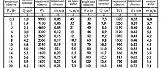
For example, a photograph of a USH4.775.000 inductor with an inductance of 5000 μH of an industrial tube (GU-81M) medium-wave marine transmitter "Volkhov-M" with an output power of 300 W (AM, CW) frequency range 400 - 535 kHz (hot end - on the left, fasteners - on the right ) Photo 1:
The diameter of the choke frame is 30 mm, length 104 mm, section width 6 mm, distance between sections 3 mm, number of sections – 7, total winding length of the choke 60 mm, winding thickness 2.5 mm, PELSHKO wire 0.25 mm, number of turns in one section 89. The diameter of the contour variometer with which the throttle works “in pairs” is 100 mm. The inductor quality factor is 55 at 460 kHz. The capacity of the blocking capacitor at the cold end of the inductor is 3900 pF (KSO-13).
Now about the alternating component of the current through the inductor. It is this that determines the reactive power of the throttle.
The lower the transmitter power, that is, at relatively high “tube” anode supply voltages, the smaller the alternating component of the anode current, the greater Ra . Accordingly, you need a choke with a large Hdr , a large inductance, with a large number of turns, wound with a thin wire, which therefore has a large active resistance, a large interturn parasitic capacitance and, as a consequence, a low self-resonance frequency and a low quality factor. That is, at low powers of the tube transmitter (less than 1 ... 3 W), due to the inductor, difficulties arise with the implementation of a parallel anode power supply circuit. This is why battery-powered, low-power communications radios typically use a series power supply circuit (Fig. 2).
And in our case this will also be the optimal solution. However, no one prohibits freedom of creativity, and if you still want to use a parallel circuit in transmitters with a power of 2 ... 5 W, then two outputs are possible. The first is the most preferable; it is, after all, to abandon the inductor (I insist) and switch to a series power supply circuit [1] of the anode circuit of the output stage, passing the alternating and direct components of the anode current through a loop coil. The second is, since the transmitter power and the anode current are small, choose the inductance of the inductor at which Hdr is almost equal to Ra . – At low power and power supply from the mains, the efficiency of the transmitter is not very important and active losses in the inductor can be tolerated. – Even with the inductor quality factor Q = 10 (well, it can’t be lower), the transmitter efficiency due to losses in the inductor will decrease by only 7% (losses are half of 1/Q, since 0.707 of the alternating component of the anode current flows through the inductor). Well, 150 mW (5% of 3 W) will not overheat the inductor.
When the inductive resistance of the inductor is equal to the equivalent load resistance in the anode circuit Ra , the alternating component of the anode current will be divided equally between the circuit and the inductor and will be 1 / √2 = 0.707 of the alternating component of the anode current. The flow of anode current into the inductor is not at all dangerous, since in the next half-cycle its inductance will give back the stored energy, albeit minus its own losses. The inductance connected to the anode is easily compensated by increasing the anode capacitance of the P-circuit. For low-power cascades this is quite acceptable, but such a significant influence of the inductor on the oscillatory system (in fact, 50% of the inductance of the inductor is included in the oscillatory circuit) imposes additional requirements on the stability of parameters (parasitic capacitances, self-inductance). In low-power transmitters, it is still advisable to choose the inductive reactance of the inductor Xdr at least 30% greater than Ra , so that the reactive part of the anode current going into the inductor would be obviously less than the current going into the circuit. Let us denote the coefficient of excess of Xdr over Ra by the letter k . Further, with an increase in the transmitter power and a corresponding decrease in its Ra , the ratio k = Xdr / Ra should be increased so that the proportion of the alternating component of the anode current branching into the choke is reduced.
From the point of view of energy losses in the inductor itself and its heating, the alternating component of the inductor current Id1 is of decisive importance. Taking into account the relatively large ratio between the inductive and active resistance of the inductor coil at the operating frequency, the modulus of its total resistance will be approximately equal to the inductive reactance, and Id1 is defined as the ratio of the alternating component of the anode voltage to the inductive resistance of the inductor: Id1 = Ua / Xdr.
Losses in the inductor on alternating current Pd1 = I2d1 Xdr / Q = ( Ea – Eamin)2 / ( kRa Q).
Assuming, for example, the transmitter power is 5 W and Xdr = 1.3 Ra , with Ea = 250 V; Ea min = 60 V (the lamp is recognized as 6P1P or 6P6S); with a throttle quality factor of 30, the losses in it will be:
Pd1 = U2 a / ( kRa Q) = 190 2 / (1.3 x 3610 x 30) = 0.256 W; at Q = 15 they will double, but still the half-watt inductor will not overheat.
Therefore, in transmitters with a power of around 5 W we do this: Xdr = 1.3 Ra . However, as a preferable option for transmitter powers of a few watts or less, we remember about the series circuit of the anode circuit (Fig. 2) - I insist for the third time!
As the transmitter power increases, voltages, currents and losses in the inductor increase and the required inductance decreases. For example, at a power of 25 W, the reactive power of the inductor is 15 W and losses of about 2 W, at Q = 15, will already cause difficulties in its implementation. Therefore, the alternating component of the anode current branching into the inductor should be smaller, and its inductive reactance, accordingly, greater. With a resistance ratio of Xdr = 2.5 Ra , the reactive power of the inductor will be 16% of the output power of the transmitter, which in terms of the absolute value of the loss power is similar to the previous case. The losses are small. Good.
With a transmitter power of 100 W, a sixth of the power is already significant and losses can be noticeable. By increasing the resistance ratio to Xdr = 5 Ra , the reactive power of the inductor will decrease, but the losses will remain the same, 0.5 ... 1 W, depending on the quality factor of the inductor. This refers to the most common values of the throttle quality factor 15 ... 30.
At powers of 400 - 500 W and above, it is desirable that the active power dissipated in the inductor should not exceed a few units of watt, and, accordingly, the reactive power should not exceed a hundred. The relation Xdr = 7 Ra allows this condition to be realized.
If you consider it acceptable to heat the inductor during transmitter operation (for example, in broadband communication radio stations not intended for long-term transmission), then it is possible to reduce k to a value at which losses in the inductor do not exceed the norm you set and, as a result, the temperature throttle overheating.
In the literature [6], the ratio for anode chokes of transmitters is known: the ratio of the lateral surface area of a single-layer winding to the dissipation power should be approximately 20 cm 2 /W. With a lower value, the throttle will overheat; with a larger value, the frame with a diameter that is too large is not rationally chosen. Since the cross-section of each section of the choke with Universal winding is relatively small, the winding is divided into sections that are spaced apart and convection cooling takes place between them, it is quite acceptable to focus on the given ratio.
The lateral surface area of the USh4.775.000 throttle is:
S side = π Nс [(D 2 in - D 2 к) / 2 + D in lс] = 7 π [(3.5 2 - 3 2 ) / 2 + 3.5 x 0.6] = 81.9 cm 2 ;
where, Nc – number of sections; Dв – outer diameter of the winding section; Dк – frame diameter; lс – section width. Considering that every 20 cm 2 of the side surface of the winding can dissipate 1 W, the permissible power dissipation on this inductor will be 4 W.
The more powerful the transmitter and the longer it operates to transmit in normal mode (this is especially true for radio broadcast transmitters), the more carefully it is necessary to design the inductor in its anode circuit, and choose a frame of larger diameter to ensure a high quality factor, or (at frequencies up to 2. 5 ... 3 MHz) use Litz wire for winding.
It is highly undesirable to choose 10–20 times more Hdr Ra The inductor for them, theorists, is an ideal coil with zero intrinsic capacitance and infinite inductance (this is where the belief came from that alternating current does not flow into the inductor). The trouble with the large ratio between Xdr and Ra is that with an increase in the inductance of the inductor, its number of turns and the total interturn parasitic capacitance increases. And with an inductive reactance 10 times higher than Ra at the operating frequency, there is a high probability that the current through the parasitic capacitance of the inductor will be equal to the current through its inductance. This phenomenon is called resonance. The loop current at resonance exceeds the HF current branching into the inductor by Q times. But since at resonance the equivalent resistance of the inductor (as a parallel oscillatory circuit) increases by Q times, and, accordingly, the current branching into the inductor decreases by the same amount, then nothing bad happens. But at frequencies above resonance, the reactance of the inductor takes on a capacitive character, and it loses its filtering properties. Therefore, the excess of the inductive reactance of the inductor over Ra should be minimally sufficient to reduce losses - one, and the operating frequency of the inductor should be lower than the frequency of its parallel resonance - two.
The inductive reactance of the anode choke at the lower operating frequency of the range should be approximately k times specified above than the equivalent load resistance in the anode circuit Ra , at which the output stage of the transmitter produces the given power. Hdr value within ± 12...15% is quite acceptable when designing a single-frequency transmitter, but when operating in a frequency band, it is necessary to adhere to tighter tolerances, since in real chokes the ratio of the upper and lower operating frequencies is rarely more than 1.5. Therefore, before designing an anode choke, it is necessary to calculate the resistance Ra . Since a number of output powers of transmitters are specified by the Technical Requirements [2], and the range of recommended radio tubes for low-power transmitters is finite, the following table can be compiled:
Table 1.
№
| Pnes | Output lamp | Eanes | Eаmin | Ra | k | ID1 | Ia0 | Idr | d | Ldr | Pd1 * | |
| 1 | 2 | 2 x 1P24B** | 150 | 40 | 3025 | 1,2 | 21 | 24 | 32 | 0,1 | 398 | 0,21 |
| 2 | 5 | 2 x 6P6S, 6P1P | 250 | 60 | 3610 | 1,3 | 29 | 35 | 45 | 0,12 | 515 | 0,48 |
| 3 | 7 | 2 x 6P30B | 250 | 40 | 3150 | 1,4 | 34 | 44 | 56 | 0,14 | 484 | 0,63 |
| 4 | 10 | 2 x 6P43P, 6P18P | 300 | 50 | 3125 | 1,6 | 35 | 53 | 64 | 0,15 | 549 | 0,78 |
| 5 | 25 | 2 x 6P37N, 6P41S | 350 | 50 | 1800 | 2,5 | 47 | 111 | 121 | 0,2 | 494 | 0,91 |
| 6 | 2 x 6P3S | 400 | 60 | 2312 | 2,5 | 42 | 98 | 107 | 0,19 | 635 | 0,91 | |
| 7 | 50 | 2 x 6P37N, 6P44S | 450 | 50 | 1600 | 3,5 | 51 | 166 | 174 | 0,24 | 615 | 0,95 |
| 8 | 2 x 6P7S | 500 | 80 | 1764 | 3,5 | 48 | 158 | 165 | 0,23 | 678 | 0,95 | |
| 9 | 100 | 4 x 6P37N | 450 | 50 | 800/3200 | 5 | 71 | 332 | 340 | 0,33 | 439 | 1,33 |
| 10 | 2 x 6P45S | 450 | 50 | 800 | 5 | 71 | 332 | 340 | 0,33 | 439 | 1,33 | |
| 11 | 2 x G-807 | 750 | 60 | 2380 | 5 | 41 | 192 | 196 | 0,25 | 1307 | 1,33 | |
| 12 | 2 x GU-50 | 800 | 120 | 2312 | 5 | 42 | 195 | 199 | 0,25 | 1270 | 1,33 | |
| 13 | 250 | 4 x 6P45S | 450 | 50 | 320/1280 | 6 | 147 | 830 | 843 | 0,53 | 211 | 2,08 |
| 14 | 2 x GS-36B | 1000 | 350 | 845 | 6 | 91 | 511 | 519 | 0,41 | 557 | 2,08 | |
| 15 | 500 | 4 x GS-36B | 1000 | 350 | 423/1692 | 7 | 155 | 1021 | 1033 | 0,58 | 325 | 3,57 |
| 16 | 2 x GU-74B | 1000 | 300 | 490 | 7 | 144 | 948 | 959 | 0,56 | 377 | 3,57 |
Notes: Power in watts, voltage in volts, current in milliamps, resistance in ohms, wire diameter in millimeters, inductance in microhenry. The anode voltages are given taking into account the fact that the lamps operate in a pulsed mode and the Eanes is present at the anode of the locked radio lamp; Eа min is present at the anode of the open radio tube . The Ra values between the anodes of the lamps in a push-pull circuit are given through the fraction . Multipliers 2 x, 4 x show how many radio tubes operate in the output stage of the transmitter under the control of a polyphase synthesizer.
* Losses in the HF choke are calculated: for lines 1…4 at Q = 16; for lines 5 and 6 at Q = 22; for lines 7…12 at Q = 30; for lines 13…16 at Q = 40. ** The 1P24B radio tube is designed for portable, battery-powered transmitters.
The calculated relationships for the values given in the table are valid for the boundary mode of classes B and C, as well as for the pulse mode of classes D and Finv :
1. Amplitude of alternating voltage at the anode of the lamp: Ua = Eanes – Eamin ;
2. Equivalent resistance: Ra = U2 a / 2 Pnes;
3. Effective value of the alternating component of the inductor current: Id1 = 0.707 Ua / kRa;
4. Determining the constant component of the anode current will require several steps:
4.1. Amplitude of the first harmonic current Ia1 = 2 Pnes / Ua;
4.2. Anode current pulse amplitude Iamax = Ia1 / α1;
4.3. DC component of the anode current: Ia0 = Iamaxα0;
where α1 = 0.604 and α0 = 0.401 are the expansion coefficients of a flat pulse with a duty cycle of q = 5 / 2 = 2.5 (when using the S9-1449-1800 synthesizer), alternating operation of two radio tubes and taking into account the actual duration of the fronts of the anode current pulses 20 ... 25 ns). To excite the transmitter output stage from the S9-1449-1800-4 synthesizer, which has a duty cycle of output pulses of 5.333, α1 = 0.587 and α0 = 0.377. If you want to make a transmitter for linear amplification in class B mode, with the initial lamp current only setting the operating point at the beginning of the linear section (for SSB or OFDM signals), then the cutoff angle will be 90 ° , and the shape of the current pulse will become cosine, expansion coefficients will be different: α1 = 0.5 and α0 = 0.319 , and the constant component of the current through the inductor will be 4% less than in the first case. And taking into account the 4% margin, the values of Ia0 in Table 1 do not need to be recalculated.
The final formula will take the form: Ia0 = 2 Pnes α0 / ( Ua α1);
5. The total inductor current loading its wire is the square root of the sum of the squares of the variable and constant components: Idr = √( I2d1 + I2 a0);
6. The diameter of the inductor winding wire at a current density of 4 A/mm 2 will be: d = 0.018 √ Idr; where d is in mm, and Idr is in mA.
7. Taking into account the fact that the inductive reactance of the inductor at the lower operating frequency fn should be k times greater than Ra , the inductance of the inductor will be: Ldr = k Ra / (2 π fn);
where fн = 1449 kHz is the lower frequency of the 200 meter medium wave broadcast band.
8. Power losses in the inductor consist of AC and DC losses:
Pdr = Pd 1 + Pd 0 = Ua Id 1 / Q + I2a0 Rdr . AC losses can also be calculated using the following formula: Pd1 = U2 a / ( kRa Q), where Rdr is the active resistance of the direct current inductor, Q – quality factor of the inductor at the operating frequency (typical values are given above).
From Table 1 it follows that at powers up to 100 W, an inductor with an inductance in the region of 400 - 700 μH is optimal (lines 1 - 10). From the experience of constructing homemade medium-wave broadcast transmitters with a range of 200 meters using 6P3S and 6P7S lamps in the 50-60s of the last century, I recall the “folk” design of an anode choke, made on a VS-2 resistor, with a resistance of 1 MΩ or more, and which contained five winding sections “Universal” of 100 turns, wires PELSHO-0.25 (Fig. 3).
Noteworthy is the accuracy of the coincidence of the inductance of the “folk” choke with the calculated inductance of the choke according to the 6P3S radio tube mode - 635 μH (Table 1, line 6).
Now about the maximum operating voltage of the inductor based on the wire insulation strength Upr max . The electrical strength (breakdown voltage) of the insulation of the PELSHO wire at a frequency of 50 Hz is 700 - 1200 volts. We assume the worst case scenario. The operating voltage should be 2.5 - 3 times less than the breakdown voltage, that is, there cannot be more than 250 volts on adjacent wires. With increasing frequency, this voltage must be reduced, however, since the main insulation is on the relatively loose silk winding (mainly air, or polystyrene impregnation, or paraffin, possibly ceresin - the frequency properties of which are good), it should not be reduced much. Let us assume that at frequencies up to 2...3 MHz this reduction will be 1.5 times, that is, on adjacent wires the operating RF voltage should not exceed 160 volts.
When winding the “Universal” type in the dimensions indicated on the inductor drawing and 100 turns in a section of PELSHO-0.25 wire, the number of double cross layers will be equal to four (this can be seen on the winding itself, on the side). If we assume the permissible operating voltage between adjacent double layers is 160 volts, then the operating voltage applied to one section will be 640 volts. The total voltage across all five sections of the choke is 3200 volts. Since with AEM the amplitude of the RF voltage on the circuit (and therefore on the inductor) can reach almost 4 Ea nes , then with a small margin, Ea nes should not be more than 800 volts. It seems that this inductor, due to its insulation, is suitable not only for the 6P3S and 6P7S radio tubes, but even for the G-807, only 135 turns will need to be wound into each section to obtain twice the inductance. An additional 35 turns form another double layer of winding, and therefore the operating voltage of the inductor can be increased to 4000 volts. Accordingly, the anode supply voltage of the output stage of the transmitter, where this inductor can be applied, will be 1000 volts. It turns out that this design is also suitable for the GU-50 radio tube (but on the condition that each section has 135 turns). Here it is, folk art, proven by more than half a century of history!
In addition to the maximum voltage of the inductor in terms of insulation strength (taken into account at the peak of modulation), there is also a maximum long-term amplitude of the alternating operating voltage of the inductor in terms of current (taken into account in carrier mode), defined as the product of the sinusoid shape factor √2 by the inductive reactance of the inductor at the lower operating frequency XL = 2π fn L (where f n = 1449 kHz for the 200 m medium wave range), and the maximum effective current value for the wire with which the inductor is wound I (mA) = ( d / 0.02)2 .
Uimax = 0.707 π fн L ( d / 0.02)2
This voltage shows in a circuit with what maximum alternating voltage this inductor can be connected so that an RF current does not flow through it more than what is permissible for its wire. When designing transmitters, it is necessary to take into account both maximum voltages Upr max and Uimax .
Article in PDF format
Part 2
Footnotes:
- In the 40-50s of the last century, this was done in low-power tube army radio stations R-104, R-105, R-108, R-109. However, this circuit has extremely low harmonic filtering, and is only applicable in low-power transmitters and tactical communications radio stations.
- Technical requirements for Individual Radio Broadcasting transmitters are given in the article “Individual Radio Broadcasting Transmission Complex”, Radio 2015, No. 9, pp. 21-26.
Device structure
This element is made from a wire type conductor wound in the form of a spiral. This conductor can be either stranded or single-core. The wire can be wound on a dielectric frame or used without it. If a base is used, it can be made of a round, rectangular or square cross-section. Physically, the inductor consists of one or many turns of conductor.
When manufacturing a choke, the following types of winding are used:
- progressive - the pitch of the turns changes smoothly along the entire length of the structure;
- universal - the distance between the turns is the same.
The first type is used to create products designed to operate at high frequencies, while reducing the value of parasitic capacitance. Such winding can be single-layer or multi-layer, and even of different diameters. Copper is used as the material for making the conductor.
An increase in inductance is achieved by adding a ferromagnetic core. Depending on the purpose of the device, different types are used, for example, to suppress high-frequency interference - ferrite, fluxtrol or carbonyl, to filter audio frequencies - permalloy. At the same time, brass is used for the inductor operating at ultra-high frequencies. The magnetic core is designed to avoid saturation mode (drop in inductive reactance).
To avoid saturation in the chokes, the magnetic core is made with a gap. When manufacturing a throttle, they try to ensure:
- required inductance;
- the magnitude of magnetic induction that excludes saturation;
- ability to withstand the required current.
To do this, the gap and the number of turns are usually first calculated based on the current and inductance, and then the maximum possible wire diameter is determined. In digital small-sized devices, the inductor is manufactured in a flat form. This is achieved by printing a conductor track in the form of a circular or zigzag line.