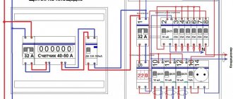
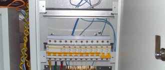
Distribution panel composition
The distribution panel consists of the following elements:
a box equipped with a door; DIN rails for mounting automation; distribution busbars connecting all conductors; groups of circuit breakers with RCDs or differential circuit breakers;
electric energy meter; wires connecting all elements.
The meter allows you to determine the amount of electricity consumed. It is installed by energy company employees who seal the device. The main switch completely cuts off power to the panel. It is usually two-pole and disconnects the phase and neutral wires supplying electricity. Its power must correspond to the sum of the powers of all energy consumers included in the apartment.
An interesting and educational video about the secrets of choosing machines and assembling a switchboard with your own hands:
Installation methods
Wiring in an apartment can be installed in two ways: open and closed.
Various cable routing options
It is the first option that is most often used for apartments; all wires are hidden under a layer of plaster in special recesses. To do this, you need to ditch the walls.
Chasing walls for electrical wiring
There are also these rules:
- Wires must be laid strictly perpendicular.
- The depth of the walls is 2 cm, so that if replacement is necessary, you can reach them.
- Cables must be secured using clamps or dowels.
- If funds allow, it is possible, and best of all, to run the cables in a special sleeve. In the event of a fire, this sleeve evacuates the wires and the danger does not spread further.
The open method is used most often in office premises, but it can also be implemented in apartments.
Open method of wiring
Initially, the wiring is laid along the surface of the walls and ceiling without recesses, then it is hidden in boxes of the appropriate size. If there are ceiling plinths and their width allows you to hide the box under them, then in this way it will be possible to implement hidden wiring, which can be reached at any time with minimal loss of the appearance of the interior.
The peculiarity of open wiring is that the sockets are not hidden in the wall, that is, there is no need to make special recesses for them.
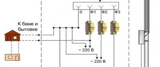
The main wire needs to be led from the distribution panel, which is located on the landing, it is brought into the distribution box, or into the panel, which is located directly in the apartment, and from there the wiring is carried out to all the points outlined in the plan.
Electrical panel in the entrance of the house Wiring diagram from the apartment panel
To calculate the required amount of cord and its cross-section, you need to check the plan and spend time measuring the distances in the apartment. But do not take the wires close to the calculations; you should always leave a margin of about 10 cm on each side. To calculate the required cable cross-section, use the calculator below.
Before you groove the walls and cut off the wires, you need to make a mark on the wall, where with a marker or pencil “draw” the drawn wires from the main distribution box to the installation points, that is, sockets, lamps, chandeliers.
Wiring markings with recommendations
The next stage is the installation of these very points, this means that first the wire is supplied, and then the socket box is mounted, the same must be done with the lighting points.
Installation of a socket for a socket box Installation of grooves for wiring Connecting a cable to the socket Finished hidden wiring
Related article:
Electrical wiring in a wooden house step by step. A separate publication provides detailed information on arranging a competent power supply for a wooden house.
How to distribute current between consumers?
At the installation stage of the electrical panel, it is important to correctly distribute electricity between consumers. Many residential electrical panels are assembled by themselves.
But at the same time you need to adhere to basic rules:
- Each consumer with an indicator above 2 kW must be registered in a separate group. To do this, the machine is fixed and the load is pre-calculated.
- If the equipment is of low power, then corresponding automatic machines are created. But you should also choose the right cable cross-section - up to three square millimeters.
- When an apartment needs devices with an increased power rating, then an automatic machine with 20 or even 32 A is used for them. There is also no need to experiment with the cable - let it be of a decent cross-section of six square millimeters.
- To create lines to the sockets, a three-core cable is used (each separately). The distribution box contains branches to each outlet.
- Lighting devices - with their own line.
- The height of the apartment electrical panel is 1000-1800 mm from the floor.
How to properly form consumer groups
When distributing electricity consumers into groups, you should adhere to certain rules:
- powerful consumers (2 kW or more), which usually include a hob, oven, water heater, washing machine, etc., should be powered by a separate switch. The cable must go from the panel to the consumer, bypassing the distribution boxes;
- two-kilowatt consumers are connected with a copper cable with a cross-section of 2.5 mm² and a 16 A circuit breaker. If you are guided by the tabular data, then for a 2 kW device a 1.5 mm² wire, as well as a 10 A circuit breaker, is sufficient, but to create some reserve, as a rule, the components of the following are installed level;
- in some cases (if the consumer power exceeds 2 kW), a 4 mm² wire with AB 25A or a 6 mm² wire with AB 32 A may be required - such components are sometimes used when connecting a hob, oven or instantaneous water heater;
- for each room you should make a separate socket line, which will branch out from the distribution box into the required number of sockets;
- the same applies to the lighting line - each of them is connected, as a rule, by a 10 A automatic machine and a 1.5 mm² wire.
It is this approach to the distribution of consumer groups that can ensure uninterrupted and safe operation of home and office electrical appliances. It is extremely undesirable to use components and materials of dubious origin, even if they are an order of magnitude cheaper than “branded” ones: with a high degree of probability, such parts will have to be replaced in the near future.
The socket line is usually equipped with a 16 A circuit breaker.
Where to start?
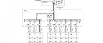
Every experienced electrician will confirm that it is much easier to begin work on installing an electrical panel and wiring, having before your eyes a floor plan indicating the intended placement of household appliances, lighting fixtures, as well as sockets and junction boxes. Having decided on the number and power of consumers, it is necessary to draw up a diagram of the electrical panel itself. A single line diagram might look like this:
In this diagram, all consumers are divided into 20 groups, for each of which the following is indicated:
- wire grade and core cross-section, mm²;
- power;
- current consumption;
- type of circuit breaker indicating the rated current.
For the uninitiated, such a diagram looks quite complicated, so you can use a simplified schematic representation of the location of the electrical panel components.
For greater clarity, the electrical panel diagram can be depicted as follows:
Or even like this:
Where
- 1 - introductory AB;
- 2 - counter;
- 3 - zero bus;
- 4 - grounding bus;
- 5–10 — AV consumers.
Having such a diagram in hand, it is much easier to figure out how to properly assemble an electrical panel.
How to install a circuit breaker: step-by-step installation instructions
Electrical panels located on the landings of apartment buildings are under the control of electricians from the management company. However, you must agree that every home craftsman is obliged to know the purpose of electrical devices enclosed in a metal box.
We suggest you figure out how to install a circuit breaker if an urgent need arises. We will tell you how the machine works and provide recommendations for choosing an electromechanical device.
This knowledge will help you replace the device yourself and take action in an emergency when the machine has tripped.
Purpose of equipment and importance of calculations
The main purpose of the distribution board is to protect the home electrical network from overloads, and the premises itself from fire
It is important to understand here that the design and calculations of all parameters must be carried out with the utmost care. For example, if the cross-section of the wiring is incorrectly calculated and the installation is of insufficient size, the load on the network can cause the insulating layer to burn
The other extreme is installing too powerful machines. In this case, electrical appliances with high energy consumption may cause the sockets to burn out.
For example, if the cross-section of the wiring is incorrectly calculated and the installation is of insufficient size, the load on the network can cause the insulating layer to ignite. The other extreme is installing too powerful machines. In this case, electrical appliances with high energy consumption may cause the sockets to burn out.
Wiring with a large cross-section that is not designed for specific conditions also leaves the network defenseless. During a load surge, protective actions may not occur because the circuit breakers will not have time to respond to critical indicators in time.
Approximate diagram of electrical panel constructionSource ul-avesta.ru
Design and principle of operation
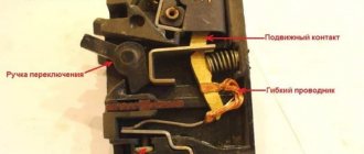
The main characteristics of the circuit breaker are the rating and the tripping speed. A single-pole circuit breaker is triggered using two mechanisms: thermal and electromagnetic releases. The first switches off the circuit in the event of an increased load for a long time, and the second – instantly, in the event of a short circuit.
The thermal protection device is a bimetal plate. When a current higher than the maximum permissible current passes through it, it gradually heats up and bends, pushing the lever that turns off the machine. After cooling, the plate returns to its place, and the switch is ready for operation again. To put it into operation, you must connect it manually.
An electromagnetic device consists of a coil with a core located inside it. When a short circuit current passes through the winding, an electromagnetic field appears, moving the core, which turns off the circuit breaker. In this case, the power contacts open, de-energizing the circuit. Since a large current passes through them, an arc occurs. It enters the arc-extinguishing chamber, where parallel metal plates are located. With their help, the arc is crushed and disintegrated.
The machine is also used as a switch by manually turning the control handle.
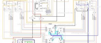
Optimal diagram of a 380V electricity metering board for a private house 15 kW
It differs from the previous one in the presence of a selective Safety Shutdown Device (number 6), it works immediately for all consumers in the house, it is also called fire protection. The installation of an RCD at the entrance to the house is recommended by the Electrical Installation Rules - PUE.
Detailed step-by-step instructions for selecting equipment and assembly are available at this link...
Metering board diagram for a private house with selective RCD, For TT grounding system
This is the most balanced scheme that can be implemented for a remote electrical metering panel at home, simple and reliable. It is suitable for everyone, and this is what I recommend collecting.
To improve it, in order to enhance the protection of the electrical network and electrical appliances at home, you can add a surge protection device (SPD).
What should be in the shield
There are several options for the layout of the panel - this concerns the installation location of the input machine and the counter. In a private house, the meter can be placed on a pole, and the machine can be placed on the facade of the house, almost under the roof.
Electrical panel
Yandex.RTB RA-1479455-2
Read about how to connect electricity from a pole to a house here.
In some apartment buildings, meters are located in boxes on the staircases. In this case, the cabinet is needed only for RCDs and automatic machines. In other cases, it stands in the apartment. When upgrading the electrical network, you will have to purchase a cabinet so that the meter can fit in there too, or buy a separate box for a meter with an automatic input machine.
Electrical circuit diagram for a small house or apartment
Yandex.RTB RA-1479455-7
Safety is very important when designing a power supply. First of all, it is provided for people: with the help of an RCD - a residual current device, which is installed immediately after the meter. This device is triggered if the leakage current exceeds a threshold value (there is a short circuit to ground or someone sticks their fingers into the socket). This device breaks the circuit, minimizing the possibility of electric shock. From the RCD, the phase is supplied to the inputs of the machines, which are also triggered when the load is exceeded or when there is a short circuit in the circuit, but each in its own section.
Secondly, it is necessary to ensure the normal operation of household appliances and electrical appliances. Modern complex technology is controlled by microprocessors. They require stable power to function properly. Having observed the voltage in our network for some time, it cannot be called stable: it varies from 150-160 V to 280 V. Imported equipment cannot withstand such a variation. Therefore, it is better to turn on at least some groups of automatic machines that supply power to complex equipment through a stabilizer. Yes, it costs a lot. But during voltage surges, the control boards are the first to “fly”. They are not repaired here, but simply replaced. The cost of such a replacement is about half the cost of the device (more or less depends on the type of device). It's hardly cheaper. When assembling the electrical panel with your own hands, or just planning it for now, remember this.
One example of a panel layout for a small circuit - for 6 machines
Yandex.RTB RA-1479455-3
The stabilizer is installed on one or several groups and is turned on after the RCD and before the group circuit breakers. Since this is a rather large device, it won’t be possible to install it in a panel, but you can install it next to it.
Also, two buses are installed in the panel: grounding and grounding. All grounding wires from instruments and devices are connected to the grounding bus. The wire comes to the “zero” bus from the RCD and is fed to the corresponding inputs of the machines. Zero is usually designated by the letter N; when wiring, it is customary to use a blue wire. For grounding - white or yellow-green, the phase is carried out with a red or brown wire.
One of the options for an assembled small shield
When assembling an electrical panel yourself, you will need to purchase the cabinet itself, as well as rails (called DIN rails or DIN rails) on which circuit breakers, RCDs and switches are attached. When installing the slats, check with a level that they are horizontal: there will be no problems with fastening the machines.
One of the options for DIN rails in the panel housing
Yandex.RTB RA-1479455-8
All machines must be connected to each other. This can be done using conductors - connecting their inputs in series, or using a ready-made connecting comb. A comb is more reliable, although it costs more, but if you take into account the time that you will spend connecting all the machines, it is unlikely that a few tens of rubles are of such fundamental importance.
Connecting comb for circuit breakers in an electrical panel: will speed up the self-assembly process
Scheme for several groups
Power supply schemes are not always simple: groups of consumers are divided into floors, outbuildings, lighting for the garage, basement, yard and local area are installed separately. If there are a large number of consumers, in addition to the general RCD after the meter, they install the same devices, only of lower power, for each group. Separately, with the obligatory installation of a personal protective device, the power supply to the bathroom is removed: this is one of the most dangerous rooms in a house or apartment.
It is very advisable to install protective devices on each of the inputs that go to powerful household appliances (more than 2.5 kW, and even a hair dryer can have such power). Together with a stabilizer, they will create normal conditions for the operation of electronics.
Also not the most complex circuit, but with a higher degree of protection - more RCDs
In general, when designing the exact design, you will have to find a compromise: make the system safe without spending too much money. It is better to buy equipment from trusted companies, but it costs a lot. But power grids are not an area where you can save money.
Advice from professionals
Now it would be useful to seek advice from professional electricians who will help you more competently connect the electrical panel and simplify its operation.
When installing a distribution board in an apartment or house, it is advisable to create a diagram of all connections with clear symbols. It can be drawn or printed on paper and glued to the inside of the panel housing door. This will allow, in the event of an emergency and the owner’s absence, almost anyone to quickly turn off or turn on the power.
For ease of maintenance and repair work, all wiring groups inside the distribution board are grouped according to the purpose of the lines. Grouping can be done using insulating tape or plastic clamps. Tags with appropriate inscriptions are attached to each group. When repairing wiring, you won’t have to rack your brains about which wire is responsible for what and avoid unpleasant mistakes.
Once again we remind you of the importance of correct connection of circuit breakers - the input conductors are inserted from the top. For reliability, inspect the markings on the devices; most manufacturers place on them a diagram of the correct connection and the question of how to connect the machine in the panel disappears by itself
Model shield
With proper assembly and calculations, there should not be an increased temperature. Otherwise, you need to turn off the shield and look for the source of the problem. If this is not done, a short circuit is inevitable.
Approximately once every six months it is necessary to tighten all the screws inside the distribution board
This is especially important when using aluminum wires in the network.
Professionals recommend not sparing three places for installing a modular socket in the panel. This will allow you to connect various tools and lighting to the panel, completely de-energizing all lines.
To create a high-tech distribution panel, it is recommended to install a voltage relay in it. This device will monitor network performance and, in the event of a critical surge or drop in voltage, will automatically turn off the load. After restoring the nominal parameters, it will turn on. In this way, you can reliably protect electrical appliances that have increased requirements for network voltage.
Outdated machines - “traffic jams” Once again, pay attention to the dimensions of the case, as mentioned above, it should be “expandable”, providing the possibility of expanding the system. A more spacious housing reduces mutual overheating of elements and increases their service life.
Pulling the contact fastenings can be combined with cleaning the inside of the switchboard housing. Dirt causes the shield elements to heat up more, and dust and cobwebs can become sources of short circuits.
Some tips
If this is your first time assembling a box, then be extremely careful and follow our recommendations on how to assemble a 220V electrical panel in a private house. Choose only high-quality machines, plugs, connectors, cables. Do not skimp on electrical wiring - your life, safety and comfort depend on it.
- Duplicate the previously drawn diagram. Hide one in a safe place (for example, in a house register), and stick the second on the door of the shield. In a year or two, you will completely forget how and what is connected to the box, so if repairs are necessary, you will have to call everything again and waste time on it. The diagram will show you all the connections in detail. It will also be useful if you are not the one doing the wiring.
- Place a sticker on each machine, indicating what it is responsible for. For example, “kitchen light” or “hall outlet”.
- Combine the groups of wires included in the box according to a common characteristic and label them.
- After connecting the voltage, watch the shield. Even if everything went well at first, after an hour or two, try the machines and cables by hand to see if they are overheating. Heating indicates that the current is too high.
And lastly, periodically look inside to determine if corrosion has begun and if dust and cobwebs need to be removed. Remember that dust conducts current. By following our instructions, you can quickly and accurately assemble an electrical panel with your own hands. .
We recommend creating a diagram not only for connecting wires to the box, but also for the location of all cables in the apartment (a room-by-room application is made with reference to constants). This will help you when making future repairs or locating a burnt cable.
1+
Electrical panel diagram
When drawing up a diagram of an apartment electrical panel, the following should be taken into account:
- The total power of consumers of the apartment's power supply system;
- Number of consumer groups;
- Power of each group;
- Place of installation of the electric meter.
The diagram must indicate all the components of the shield, indicating the full name, rating and protection class - this is necessary for replacing components or additionally installing new ones.
In old Soviet-built houses, the wiring was not grounded; accordingly, on the electrical panel diagrams of apartments in such buildings, as in fact, there will be no grounding bus. If the house is newly built, or the building’s power supply system has been reconstructed with a grounding loop installed, then the distribution panel diagram will also include a grounding bus.
Depending on the number and power of electricity consumers, the distribution panel diagram can be simple or quite complex. But the shield assembled using it must in any case ensure safety and ease of use of the power supply system, therefore the list and location of components in the circuit is carefully thought out.
Drawing up a diagram
Modern power supply systems involve the use of a three-wire cable, where one wire is a phase, and the rest are ground and zero. Given the growing power of devices, it is also necessary to divide them into groups, which allows to increase the service life of the wiring. Guided by these principles, we proceed to drawing up a diagram of the shield.
It is mandatory to install a protection device on the input cable, which will protect the internal network from overvoltage. Then they install a voltage relay to control surges in the network, after which they proceed to the installation of groups and individual lines. It is worth noting that for powerful devices, in addition to switches, additional RCDs or differential circuit breakers are used. Such organization of the home electrical network is not only safe, but also convenient. If necessary, you can turn off the machine and turn off the washing machine. You can also turn off the RCD and de-energize all consumers included in the global group.
What elements does the electrical panel consist of?
Most often, the switchboard contains such components.
- VA. An input circuit breaker (or VA) is installed to protect the wiring loop. The main incoming conductor is connected to the VA terminals. Often, for convenience and comfortable use, a switch is installed in front of this device. Its installation is also rational because it makes it easy to de-energize the circuit going into the apartment in order, for example, to replace failed elements in the electrical panel.
- Electricity meter. This device comes only after VA. Its function is to calculate the energy consumed. Many people install an electric meter outside the switchboard along with the VA. For example, this could be a platform or vestibule of an apartment building.
- RCD. This element is necessary to prevent fire or electric shock. It can be one in the circuit (attached after the meter) or several of them are installed on each line where large energy consumption is expected (air conditioner, water heater, electric stove, etc.).
- Linear machine. Connecting the machine in the apartment panel is necessary to control individual lines (lighting or household appliances). Their function is to break the electrical circuit when a short circuit or overload occurs. Thus, they keep wiring and energy-consuming devices intact.
- Difavtomat. This device replaces the RCD and the machine combined. Its use is advisable if space in the shield is limited.
- Busbars for connection. These elements are needed to connect working grounding and neutral conductors.
- RackDIN. Necessary for mounting devices in the electrical panel. Not a single machine circuit in an apartment panel can do without this element.
- Tires for distribution. This part is needed for linking automatic devices, automatic devices and RCDs. It can be a working zero, or as a current conductor.
To connect a three-phase outlet, the number of elements used in the electrical panel is no different from a single-phase one. True, they use components suitable for this type of network.
How do protection devices work?
You can determine at first glance that the plug or machine has been knocked out. The lever or toggle switch of the protective device is in the off position.
- If you have old-style plugs, their power button will be pressed.
- In such devices, the fuse link may burn out and you will have to use a special device to diagnose the breakdown.
- For this purpose, a multimeter is used, which must be set to ohmmeter mode or a regular circuit probe.
Let's look at the main reasons why a plug in the meter can be knocked out.
Short circuit
When there is an unexpected surge in current in the circuit, the wires heat up. This is followed by a drop in voltage, which leads to burnout of the wiring. Sometimes it leads to a fire.
The cause of the accident is usually an outdated electrical network, damaged insulation, or water getting into the wiring.
Wiring overload
When ignorant people connect several devices to one power strip, the inrush current exceeds the rated current. Powerful appliances such as refrigerators, washing machines, and water heaters can cause a voltage drop when starting up.
To prevent such excesses, it is necessary to carefully check the number of devices connected to a specific outlet group and their operating power.
Breakdown of a household appliance
If your home appliance has expired or there is damage to its contacts and other components, electrical damage to the device may occur. This often leads to a short circuit or tripping of the protection device.
Circuit breaker malfunction
A common reason for breakouts is loose contacts, which cause overheating inside the fuse.
Because of this, it triggers falsely, which can cause damage.
- People often don’t know what to do if the traffic jams in their apartment are broken.
- By studying the necessary information, everyone can learn how to solve the problem of power outages.
- You can not only constantly call an electrician or some kind of emergency service, but also try to figure it out yourself.
Of course, if it is within your power and you have basic knowledge about electricity. This article provides simple instructions on how to turn on the plugs.
Option 5
In this option, difavtomats and conventional circuit breakers are used to protect groups. Automatic residual current switches (RCBOs) protect the cable from overload, from the action of short circuit current and protects a person from electric shock. Each difavtomat must be supplied with a phase and a zero. After logging out of these devices, you cannot combine zeros either. The neutral working conductors of the remaining groups, which are protected by conventional circuit breakers, are connected to the input common zero bus.
This article presents the simplest options for single-phase electrical panels. They discuss almost all protective devices, show how they need to be connected and contain descriptions of the use of one or another option. Based on your individual situation, you must develop your own scheme. Remember that it must meet all modern electrical safety standards.
Summing up
Key technical points to remember from this article:
- The supply wire is connected to the fixed contact of the circuit breaker. On almost every machine such a contact is located on the top.
- Only the phase passes through a single-pole circuit breaker, phase and zero pass through a two-pole circuit breaker, and 3 working phases pass through a three-phase circuit breaker. In the latter case, it is also necessary to use a phase indicator to determine the correct phase rotation.
- Phase and zero must pass through the RCD and differential circuit breaker.
- To connect wires to the circuit breaker, use special crimping lugs and press pliers. Especially when installing multi-wire cable.
- Before connecting the cable, it is necessary to remove sufficient length of insulation from the core. Otherwise, insulation will be the first cause of poor contact.
- The main circuit breaker is mounted before the electric meter in order to ensure the ability to quickly replace the electricity meter in the event of its failure.
Before any electrical installation, you should check the regulatory or technical documentation. Only then will all work with electrical devices and consumables be considered correct, and most importantly, legal.
Regulatory documents and rules
The requirements for installing an electrical panel are specified in GOST 51321.1-2007. The panel is a switchgear operating under voltage up to 1 kW. Its features are discussed in Chap. 4.1. 7th edition of the PUE. The requirements for the ASU in a residential multi-storey building are specified in GOST 51732-2001, and for switchboards - in GOST R 51628-2000. Since the apartment electrical panel is a low-voltage switchgear and control device, you need to refer to GOST 51321.1-2007.
Basic requirements and installation rules
GOSTs and PUE indicate the correct way to connect the panel.
The standards note several points:
the presence of a complete circuit with the rating of the circuit breaker, the type and cross-section of the cable, installed and one-time power, protection parameters of the housing shell; installation of modules equipped with a nameplate inside or outside is permitted; mandatory affixing of the “Caution Voltage” sign in the form regulated by GOST R 12.4.026; selection of cable cross-section for laying inside according to the rating of the circuit breakers;
selection of wire insulation capable of withstanding an alternating current voltage of at least 660 V; protection of bolted connections from vibrations and short circuits with disc springs, controllers, spring washers, tips; assembly of neutral conductors on N and RE buses; connecting the REN wire to the RE panel; use of terminals to protect input and output wires; performing work using screwdrivers with slots for screw slots, tools with insulated handles; cable marking with colored PVC tubes - blue/light blue (working zero), yellow-green (protection zero), red/brown (phase); marking of N and RE bus contacts according to the serial numbers of protective circuit breakers; connection of one conductor per bus terminal N or RE; designation of outgoing cables with round (line voltage from 1000 V), square (voltage up to 1000 V), triangular (control) tags.
Which case is more reliable - metal or plastic?
Metal distribution panel in a wooden house
The apartment panel is available in metal and plastic casings. The choice of material depends on the project, design specifications and financial capabilities of the user.
The metal electrical panel has a number of features:
- reliable landing on protective zero;
- high anti-vandal characteristics;
- good fire resistance;
- installed on the street or in the entrance;
- moisture resistance class IP31 – IP54.
The disadvantage of a metal case is the need for grounding. The third wire will need to be brought out from the main power supply panel of the apartment.
Plastic electrical panel near the door in the hallway
The plastic case has the following characteristics:
- suitable for interior design;
- can be built into a special niche;
- resistance to wet environments;
- beautiful transparent or tinted door;
- excellent dust resistance.
If the insulation is poor, there is a risk that the plastic will ignite and cause a fire. In this case, it is better to purchase a box made of textolite.
Do-it-yourself circuit diagram for connecting a machine in an electrical panel: advice from experienced electricians
It is very difficult to imagine a modern apartment without various electronics, which create some inconvenience with connection and high load on the electrical network. To increase electrical safety and reduce load, you should consider separate control of devices and install a control unit in the electrical panel of the house. The laying of cables and the correct layout of the electrical panel can be done independently in the apartment, but as for completing the work, you cannot do without a specialist, since you need to have an understanding of the structure of the distribution panel, various standards, diagrams and be able to make connections.
Requirements for electrical panels
Choosing and purchasing an electrical panel is a very important and responsible matter, since not only the ease of use of electrical appliances, but also the safety of the home depends on this choice. There are certain requirements for shields and their installation, which are specified in GOST 51778-2001 and PUE . Below you can read a list of these requirements and rules regarding the shield and its installation:
- electrical panels must be filled out in accordance with the technical documentation that comes with them, which reflects the number of installed machines and their rated current;
- the shield must have an electrical safety symbol indicating the voltage (220V or 380V);
- The shield must be made of non-flammable material and have a coating that does not conduct current. It can be plastic or metal coated with special paint;
- it is necessary to make connections inside the panel, making markings on the wires that indicate the groups of connected devices;
- jumpers between machines are made using special bus drives;
- the doors and the panel body must be grounded. It is also necessary to provide ears or some other element on the doors so that the inspection organization can seal it;
- When buying a shield, check the technical passport, which will reflect: the type of shield, name of the manufacturer, certificate, GOST, rated currents of the input and protective devices of the RCD, voltage and frequency, rated current of the shield, rated operating currents of the RCD devices, degree of protection, class of the shield, instructions by connection, weight and dimensions.
If you adhere to the above requirements, as well as the requirements noted in GOST and PUE, then you will be able to buy, install and connect the panel at home without unnecessary difficulties. In addition to this knowledge, you will also need to have on hand an electrical diagram of the control panel so that no difficulties arise when housing office employees accept work.
Drawing up an electrical panel diagram
An important step in installing an electrical panel is creating its diagram. There are several explanations for this. Let's say, if you plan to repair or modernize the wiring in your apartment in the future, using the diagram you can quickly establish what each machine and part in the panel is responsible for. You will also need the diagram when accepting work as an electrician . In addition, connecting wires with such a diagram on hand is much easier. You can either draw it manually or in specialized programs, and then print it.
The electrical circuit is created in several stages. The first step is to find out what kind of electrical system is in the house, then divide all points of electricity consumption into several categories. After this, based on the existing data, a shield diagram is created. It is extremely important that the diagram used symbols, which are described in detail in GOST 21.614 “Conventional graphic images of electrical equipment and wiring in the original.”
So, as mentioned above, all work begins with determining the power supply and grounding system in the apartment, since the connection of the panel will depend on this. You can find out by looking at the sign on the floor or by going to the housing office. Often, three systems TN-C, TN-S, TN-C-S are installed in residential buildings.
It is worth immediately noting that the first system was created according to old GOST standards and was used in houses that were built before 1998. The TN-C system is represented by two-core copper or aluminum wiring. A three-phase cable (L) with one conductor PEN, in which ground and neutral were combined, went to the floor distribution board. The last two systems are used in modern homes. A three-core copper wire is laid in the apartment, and a cable with three phases (L), neutral (N) and PE ground (S) is connected to the switchboard.
Breaking it down into points
After this, the points are divided into several groups for connection. Many people wonder: why all this? Yes, very simple. This way you can use materials more economically and simplify the installation of the electrical panel. You can group as you wish. You can combine living quarters under one machine, hang a boiler on another, air conditioning on a third machine, etc. Moreover, each group needs a machine gun with its own characteristics .
For sockets you need 20A circuit breakers, for lighting systems and switches - 16A circuit breakers, for an electric stove - from 32A, for a boiler, washing machine and air conditioner - 25A. By the way, it is worth considering that sometimes it may be necessary to install additional 25A and 40A circuit breakers on sockets, lighting and switches.
Once you have clarified the power supply and grounding system of the house, and divided the connection points for electrical appliances into groups, start drawing the diagram itself. If you have all the necessary data, its creation does not take much time. Again, it is worth considering that you have concepts with symbols from GOST 21.614 . Having finished with the circuit, you can begin connecting work. Having the appropriate experience, installation will not take you much time.
Installation of electrical panels
Before you begin installing the electrical panel, you need to do two things. The first is to purchase the necessary materials, the second is to arrange a place for it. Now let's talk about everything in order and start with choosing a shield.
It’s worth noting right away that shields can be built-in or wall-mounted , and their choice depends on several factors. If the wiring is hidden, then pay attention to the first type, and if it is open, then to the second. At the same time, do not forget that new apartment projects provide a special niche for shields. As for apartments in old buildings, there is no such thing there and therefore you will have to hang a hinged panel. If it doesn’t really fit into the interior, then it can be disguised using drywall. You can also make a niche in the wall. To do this, you need to be sure that the wall is not load-bearing.
Secondly, the dimensions of the electrical panel depend on the number of installed machines. According to GOST, there are shields for 6, 12, 18, 24, 30 circuit breakers or 6, 9, 12 threaded fuses . By the way, you need to take the shield with a reserve. If you planned to install 12 machines according to the scheme, then it is recommended to take a shield for 18. This way, you can protect yourself from additional expenses in case of installing additional machines.
General information
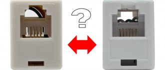
There are many types of such equipment on sale. Prices, sizes, materials of manufacture will be found for any buyer and purpose. But first you need to understand what this electrical installation component is.
Purpose of the mounting box
Most people, when buying such equipment, pay attention only to the appearance of the product.
How it will look in the surrounding environment is, of course, important. But first of all, such boxes must meet the following requirements: But first of all, such boxes must meet the following requirements:
But first of all, such boxes must meet the following requirements:
- All installation and maintenance work is carried out under conditions that meet safety conditions.
- Metal enclosures are grounded.
- The material of the box must withstand temperature fluctuations, precipitation of all types, and solar radiation.
Plastic boxes are safer and look more attractive than metal ones. Such electrical installation devices go by different names. Some call them meter cabinets, others call them boxes. There is no single standard, and manufacturers define products in their own way. However, they all must be practical and convenient.
Most support mounting internal components using a standard DIN rail, allowing you to mount the equipment yourself. In addition to the meter, it is installed by trained specialists after receiving permission from the supervisory company.
Features of the box design
According to the rules, all protective boxes suitable for installation must comply with security levels from IP 20 to IP 65. In addition to size and color, they can be:
- Open installation.
- Secret.
- For floor mounting.
- For inline location.
- Invoices.
- Solid or collapsible.
Quality requirements
Even for such a simple-to-manufacture device as a box for an electricity meter in an apartment or on the street, high-quality execution of all its components is important. This will enable the owner to take readings comfortably and safely
When purchasing a metal cabinet, you need to pay attention to the following points:
To make the box itself, steel with a thickness of at least 1.2 millimeters is used. Thin iron will not provide sufficient strength and long-term use. Practice shows that the door of such shields is the first to sag. This violates the tightness of the structure and threatens the destruction of electrical devices installed inside. Industrial production involves testing finished samples in installations that simulate the most difficult weather conditions. If they pass the test, this means that the quality of the paint application is good and the sample will last a long time. Large manufacturers guarantee a service life of up to 15 years. Availability of a locking device. An outdoor box for an electricity meter must be selected with a lock that can be locked with a key. Its design can be any, the main thing is that there is a seal between the metal of the door and the cylinder. The thickness of the constipation is also important. The hole must be sealed. If there is a window for data control, then a seal is also needed here. Fastening must be provided with screws or self-tapping screws, since even the best glue dries out and the glass falls out. The cabinet door must be grounded. Since the first touch falls on it, if it is energized, you can get an electric shock with its help. Except for the door, the entire body is grounded
It is best if several bolts are provided for these purposes. Particular attention should be paid to the quality of seals. They are made of plastic rubber in the shape of a ring. There should be no breaks in it to avoid leakage. Semicircular bends along the edges of the door and body ensure a tight fit of the sealing gaskets, and if they break, they prevent water from getting inside.
There should be no breaks in it to avoid leakage. Semicircular bends along the edges of the door and body ensure a tight fit of the sealing gaskets, and if they break, they prevent water from getting inside.
How to properly connect a circuit breaker in an electrical panel
A modern switchboard in a home should be equipped with protective equipment, such as a circuit breaker.
To correctly connect the machine in the panel, you need to know the rules and features of the procedure. The circuit breaker is a small lever installed in the panel. The principle of its operation is that it allows you to turn off the electricity supply manually or automatically.
Automatic shutdown is needed in the following cases:
- short circuit;
- overload of electric current supply.
In other words, such devices turn off electricity when the current exceeds the short circuit power.
Classification
Before purchasing a circuit breaker, an electrician must decide on the number of poles. This indicator depends on the phases of the network.
Automatic machines are divided by the number of poles:
- single-pole;
- bipolar;
- tripolar;
- four-pole.
Single-pole and double-pole circuit breakers are installed in a single-phase network. Three-pole and four-pole are suitable for three-phase networks.
The growmir channel talks about installing and connecting the machine to the bag machine yourself.
How to choose a machine?
The correct choice of an automatic switch for a panel is a guarantee of balanced operation of the entire electrical circuit in an apartment or other room.
It is recommended to choose machines for brand shields:
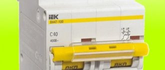
- EKF;
- Legrand;
- I.E.K.;
- Hager;
- Merlin Green;
- Schneider Electric;
- ABB.
When purchasing a circuit breaker, experts recommend paying attention to the labeling, which contains all the information about the product.
When planning the choice of device, you need to pay attention to the following parameters:
- Rated current value. The higher it is, the more voltage is required to automatically turn off the machine. The parameter is selected based on the cable cross-section, and not on the load power.
- Number of poles. This parameter is selected based on the number of phases. The number of places for machines corresponds to the number of poles.
Installing a circuit breaker in an electrical panel with your own hands
When installing a machine in an electrical panel, you need to focus on the rating of the device and the cable cross-section, which is determined based on the maximum load of the wiring.
Before installation, evaluate:
- rated mains voltage;
- maximum current;
- rated current.
To calculate the load, add up the total power of energy consumers (sockets, household appliances, etc.) and calculate the current power using the formula given below. Knowing this parameter, they decide which machines to connect.
You can also calculate the load using an online calculator:
When connecting independently, you must:
- ensure high-quality connection;
- check if all terminals are tight;
- follow the markings;
- focus on GOSTs and rules for the construction of electrical installations (PUE);
- observe electrical safety;
- observe fire safety.
During the installation of the machine, it is necessary to de-energize the panel and ensure that it is not possible to automatically turn on the electricity.
According to the PUE, it is recommended to avoid sharp turns when laying electrical wiring. Electric current passing through cables produces excessive heat in bends. The wires also form kinks, which can cause malfunctions.
What tools will you need?
To install a circuit breaker, you will need the following tools:
- DIN rail;
- pliers;
- stripper (insulation stripping tool);
- indicator screwdriver;
- wire cutters or cable cutter;
- regular screwdrivers;
- crimper (device for crimping tips).
Entrance from above or below?
You can correctly connect the machine in the panel armed with basic knowledge:
- only incoming wires are routed from above;
- outgoing wires are installed from below.
Installation of a single-pole circuit breaker
Single-pole circuit breakers are connected to a DIN rail; all you need to do is simply snap the device into place. Experts recommend using a limiter when connecting so that the elements stand statically.
When installing a single-pole circuit breaker, the upper terminal must include the RCD phase and the input device. The phase of the protected circuit must leave the lower terminal.
How to install a two-pole circuit breaker
A two-pole circuit breaker must also be connected to a DIN rail. If there is still space on the rail, you must use a limiter.
Installation of the machine is done crosswise:
- The same phases are supplied to the upper and lower left terminals;
- A zero is supplied to the right terminals, and a zero goes out.
Installation of three-pole and four-pole circuit breakers
To operate a three-pole switch, electricity is supplied through the top in the order from left to right:
The phases leave in the same order from the bottom of the machines.
When installing a four-pole device, a zero phase appears. It is mounted the same way from left to right in the following order. The current is supplied from above, at the end of the row one terminal is added at the top and bottom, which act as a zero pass.
Connecting wires
In order to connect the machine, it is necessary to calculate the exact amount of wire. The excess will need to be cut off. Using a stripper, at least 10 mm of insulation at the end of the cable is removed.
To connect a cable with a monolithic core, no additional steps are required. Experts recommend making a U-shaped bend at the ends to ensure better contact.
Bend wire for best grip
Stranded wires must be terminated using a crimper. For this purpose, special tips NShV or NShVI are used. If it is necessary to connect two multi-core cables, use the NShVI-2 tip. Termination is necessary to maintain the integrity of the wires and ensure maximum adhesion to the machine contact.
Termination of stranded wire
After preparation, the wires are connected to the terminals and tightened with a screwdriver. Experts recommend not tightening the bolts completely, otherwise you may damage the machine body. Using an indicator screwdriver, check the supply of electricity to the connected device.
Examples of electrical machine connection diagrams can be seen below.
Schematic representation of the wiring connection through the meter Schematic diagram of the generator installation Example of an electrical diagram (planning) Schematic representation of the wiring connection through the meter (three-phase installation) Connection diagram of the differential current circuit breaker Connection diagram of the input circuit breaker Loading...
“Connecting machines in the panel”
The channel “EVERYONE CAN” tells how to connect machines in a panel with your own hands.
Source: https://razvodka.net/connect/podklyuchenie-avtomata-v-shhitke-17979/
Electrical panel assembly
When the panel diagram has been created and the electrical wires have been laid around the apartment, we proceed to assembling the panel. If desired, you can order a prepared shield, which all that remains is to install and connect the input cable.
Marking and installing DIN rails
First, markings are made of where the modules will be located and how long the slats are needed. During the fitting process, they also take into account the distance between the rows, if there are several of them, as well as the distance between the zero and ground buses. When the marking is ready, the slats are installed in the required places.
Installation and switching of modular devices
At the stage of installation of modular devices, automatic machines and additional devices are installed on a DIN rail. They are also connected to each other. First of all, they install an input circuit breaker, then voltage relays, RCDs and differential circuit breakers, which are located in front of conventional switches.
Organization of cable entry into the electrical panel
At the stage of cable entry, it is necessary to make holes in the shield. As a rule, all insertion points are provided by the manufacturer, so it is enough to squeeze out the plastic. On one side, a general network cable is installed, which is connected to the input circuit breaker, and on the other, internal network wires.
Assembly sequence
To install the incoming electrical panel in an apartment or private house, purchase 2-4 meters of colored installation wire grade PV3, PV1 with a cross-section of 4-6 mm²:
- for zero – blue;
- for phase - white, red, brown, black;
- for grounding - yellow-green colors.
To assemble modular equipment, the following consumables are purchased:
- combs;
- end caps;
- cross-modules or zero busbars for RCDs;
- plastic clamps for fixing cables;
- limiters for DIN rails.
Housing installation
Load-bearing walls are not suitable for installation; it is not prohibited to construct a false wall from plasterboard for electrical installation of a built-in panel. The location must meet the requirements:
- availability of free access;
- from the edge of the box to the slope, jamb, corner of at least 15 cm;
- There are no gas pipes nearby.
Comment!
The air humidity level in the room where the electrical panel is located is not higher than 60%.
Sequence of actions when installing the shield:
- Having retreated 1.4 m from the floor, using a level, draw 2 lines - the bottom horizontal and one vertical;
- apply the body to the markings and outline it around the perimeter;
- using a grinder, make cuts at least 9 cm deep;
- a cavity is hollowed out using a perforator;
- fastening elements are mounted on the rear wall of the case;
- Mark the holes in the cavity and drill them with a hammer drill;
- drive in dowels;
- fasten the box to dowel-nails.
The gaps between the walls of the niche and the box are filled with concrete, other building mixture or polyurethane foam.
Cable entry
High-quality panels have technological holes for entering cables with a diameter of 16-20 mm under a standard-sized corrugated pipe; in low-grade products they are drilled or sawed out.
When connecting an electrical panel installed in a niche, perform the following manipulations:
- remove the plugs or squeeze out the stuffing box plates;
- the input cable is inserted into the technological hole of the box, it is placed close to the input machine;
- apply it to the comb, fix it with a plastic clamp, remove excess tie with wire cutters;
- mark the cable in accordance with the diagram;
- the remaining cables are inserted and labeled in the same sequence;
- attach a removable cover to the box, mark the entry points of the cores with a marker;
- Use the blade of a construction knife to cut holes.
The electrical panel plug is put in place, after which it is necessary to assemble and switch the modular devices.
Cabling
Each cable is marked as in the diagram, the insulation layer is removed without damaging the conductors. To ensure that there is enough length, two heights of the box are measured from the insertion point. When routing wires in the panel, make sure that insulating materials do not get into the terminal contacts. Do not connect wires of different sections to one machine.
For better contact, the end of the wire is bent in the form of the English letter “U”. For switching multi-core wires, lugs are used:
- NSHV;
- NSHVI.
Special devices ensure reliable contact.
Shield installation
It is not difficult for a person who has basic knowledge of electrical engineering to assemble a single-phase panel with automatic circuit breakers. First, all modules are secured with clamps to the first DIN rail exactly according to the diagram:
- switch;
- UZM;
- RCD (by number of consumer groups);
- differential machine.
Comment!
To prevent modules from moving on the DIN rail, limiters are installed.
The machines are installed on the second DIN rail, each with its own RCD, starting from the right side. To power equipment (automatic devices, RCDs), combs are used. Wiring sequence:
- switch and UZM;
- UZM and the first RCD;
- each RCD with its own zero bus, it is installed in the lower part of the box;
- The machines are connected to the RCD.
After assembly, the shield is installed in place, the input cable and load wires are connected.
Connecting consumers
Disconnect the input cable coming from the control panel (access panel). The wires are distributed into three bundles:
- L - phase;
- N – zero workers;
- PE – zero protective.
Comment!
After connecting the input cable to the switch (input circuit breaker), the meter and circuit breaker terminals are sealed by the inspector of the energy supply organization.
The sequence of connecting the protective zero wires to the PE bus:
- input core for the large terminal;
- cables from consumer groups;
- metal parts of the box (body, door).
One part of the cores of the working zero is connected to the zero busbars of the RCD, the second part to the central zero busbar. The phase conductors are crimped and clamped with machine terminals. The last thing to connect is the input cable.
Final installation of the electrical panel. Connecting consumer groups
Pre-assembly and testing work allow you to install the electrical panel by placing it in a prepared niche, hanging it externally, and connecting groups of consumers. You should wait until finishing work is completed, which may contaminate the device, increase the humidity around it, or get it wet.
The procedure is as follows:
- Secure the installation process by excluding the supply of current to the equipment input. In an apartment building, it is worth hanging a special sign on the control panel or the distributor on the floor.
- Remove the protective cardboard or special cover, remove all contents from the box, take the wires out and secure them, and clean the case if necessary.
- Insert the DIN rails with installed modules inside, secure with screws or clamps.
- The protective and working zero busbars are mounted in standard places and insulated in a metal box.
- Zero protective, neutral and phase wires are divided into separate bundles, fixed with plastic clips, and the presence of markings is checked.
- The protective zero cables are attached to the PE bus; the additional length of the reserve is tightened with couplings.
- After entering, all groups of consumers from the protective bundle are connected in series, the ends of the multi-core wires are crimped with the NShVI tip, the rest are stripped with a stripper to 1 cm, the excess is cut off.
- Final marking before clamping into terminals using heat shrink tubing or cable markers.
- The metal door is connected with a green-yellow cable to the protective zero bus.
- Cables connected to the buses of group RCDs are separated from the working zero bundle and brought out into a separate bundle. They are connected to the appropriate bus with a right angle bend, they are stripped, marked and fastened as in the previous group.
- The location of the phase cables should be on the opposite side of the box from the zero side. If there are special niches in the box, they are inserted and secured, branches and bundles of wires are secured with ties.
- In accordance with the diagram, the necessary cables are inserted into each circuit breaker. Marked and trimmed as necessary, secured.
- The working zero and input phase are connected to an automatic switch or input load switch to the upper terminals.
- The correct installation and cable markings are checked according to the working diagram, and all terminals are tightened with a force of 0.8 Nm.
Main process
So, in the initial position we have an electrical panel in which the products will be installed, as well as all the wires (input and outgoing to consumers).
Let's look at the instructions for dummies using the example of connecting a two-pole circuit breaker in a panel:
- The first step is to turn off the power and check its presence using a multimeter or an indicator screwdriver. we provided to the readers!
- The machine is installed on a special mounting DIN rail and snapped into place with a latch. You can do without a DIN rail, but it is less convenient.
- The conductors of water and outgoing conductors are stripped to 8-10 mm.
- You need to connect the input zero and phase to the two upper terminals (do not forget about the recommendations indicated above).
- Accordingly, the outgoing zero and phase (those that go to electrical appliances, sockets and switches) are fixed in the two lower holes.
- After this, the place must be checked manually for reliability. To do this, you need to carefully take the conductor and move it in different directions. If the core remains in place, then the connection is reliable, otherwise be sure to tighten the screw again.
- After all electrical installations, the robot is supplied with voltage to the network and the functionality of the product is checked.
That's all the instructions for connecting a circuit breaker in a single-phase circuit. As you can see, there is nothing complicated, you just need to be careful. We also recommend watching the video tutorial, which discusses the connection process in more detail:
Visual video instructions
Installation of a low-quality single-pole circuit breaker
Types of electrical panels
The manufacturer produces various types of shields, both for indoor and outdoor installation. Panels for outdoor installation are attached with dowels directly to the wall of the building. If the surface is made of wood (fire hazardous), then a non-combustible material, for example, asbestos, is placed between the surface and the shield. Such shields are installed in places where they do not interfere with normal human life. However, the location must be accessible and convenient to use. The outer shield rises 12-18 cm above the wall surface and this factor must be taken into account when determining the installation location.
The panel for internal installation is designed for installation in a specially prepared niche. This type of shield is always at the same level with the surface, therefore, it does not pose any danger to normal life.
The body of the shield is made of either metal or plastic. The size can be selected to suit any specific conditions.
As a rule, choose a shield of the appropriate size. It must freely fit all circuit breakers, all RCDs and at the same time there must be enough space for placing wires. Apart from this, nothing should interfere with the connection.
It is very important to decide in advance on the number of machines and select an electrical panel of appropriate dimensions. At the same time, we should not forget that it is possible to expand the electrical network
In this case, there should be room in the shield for at least two machines.
Making a diagram of the electrical wiring in the apartment
The main mistake of novice masters is incorrect planning of the upcoming work. When drawing up a network diagram, you cannot estimate the location of lamps and switches “by eye”; it is necessary to provide for every little detail so that the apartment does not have to be overgrown with tees and extension cords. Therefore, there is no way to do without drawings and calculations.
Do-it-yourself electrical wiring in an apartment: step-by-step instructions for drawing up a diagram:
1. Draw a general plan of the apartment, mark the location of windows and doors.
2. We schematically arrange furniture, plumbing fixtures and household appliances. Don’t forget about large accessories so that a mirror or picture does not end up in the place of the planned socket or switch. For greater clarity, electricity consumers can be highlighted in red. For example, like this.
3. We simplify the drawing: we remove furniture and other items that do not need to be connected to the network, and at the location of electrical appliances we mark sockets (single, double - it all depends on the number of consumers).
4. For convenience, we recommend thinking over a schematic designation for all network elements or using a hint.
5. As a result, we received the power part of the electrical circuit in the apartment.
6. Now let's start arranging the lighting fixtures. Typically, chandeliers are placed in the center of the room. To determine the location of the wires for them, you need to measure and halve the length and width of the room and mark the intersection of lines from these points on the diagram. In rooms with irregular geometry (L or U-shaped), you need to divide the room into 2 or 3 parts and find the center in each section. If additional lighting is provided with a network connection without the use of sockets, mark these devices on the diagram as well.
7. It remains to think about the location of the switches. It is clear that they will be located at the entrance to the room or near the zone lighting devices; the main thing here is to take into account which way the door will open, so that turning on the light does not turn into a game of touch in complete darkness. Switches are conveniently located on the inner wall of the room (with the exception of the bathroom and toilet).
The result of the preparatory work will be a general drawing, which will combine the plan of the power line, the layout of switches and lighting fixtures.
By the way, if you are not familiar with drawing, but you are familiar with a computer, you can make all the calculations and planning in special programs, for example “Electrician”, “DIA”, “sPlan”, “AutoCAD”, “Visio”.
How to choose a machine?
The machines in the apartment panel must comply with the established rules, otherwise their operation will be dangerous and may lead to unpleasant consequences. When choosing a new device, it is important to pay attention to the following parameters:
- Type that determines the purpose (“A” – breaking long-distance circuits; “B” – lighting lines of general functionality; “C” – electrical devices with moderate currents; “D” – for active loads exceeding standard values; “K” – inductive volumes; “Z” – electronics);
- Number of poles (for a single-phase network - one or two, for a three-phase network - three or four);
- Rated voltage corresponding to this network indicator;
- The maximum operating current of the line, calculated from the power of all devices and equipment connected to the line;
- Breaking capacity when permissible values are exceeded.
Read here! Mercury counter: main types and characteristics of devices. TOP advantages of the manufacturer. Instructions and connection diagram
If you need to replace an old machine, then you need to focus on the previous device (if its operation was completely satisfactory). When the package being replaced was far from perfect, you can start from the parameters that were not satisfactory.
Design of a standard circuit breaker
For example, we will use the BA47-29 series switch as the most popular switching device with an affordable pricing policy. Before you learn how to properly connect a circuit breaker to a single-phase network, you need to consider its design.
The BA47-29 series circuit breaker consists of the following elements:
- A copper terminal connected to a fixed power contact. Most often, the supply wire is installed exactly in this place.
- The movable contact, which makes the switching, and the copper stranded conductor, has a sufficiently large cross-section.
- Arc chamber.
- A special thin plate with a hole through which gases formed after the arc escape.
- An electromagnetic release, presented in the form of a simple coil. The stranded conductor from the moving contact is soldered to the coil.
- Plastic, fully dielectric handle.
- A bimetallic plate that acts as a thermal release. The plate is located immediately behind the reel.
- A special screw for adjusting the bimetallic plate. The screw is not installed on all models, and adjustment is made at the manufacturer.
- The lower copper terminal, from which the conductor goes directly to the consumer.
A three-phase machine has a similar design, but instead of one terminal, it uses three, isolated from each other.
Features of connecting SIP to the input circuit breaker
Self-supporting insulated wire is widely used to transmit electricity to the home network from overhead power lines instead of conventional cable. Despite all the advantages of this conductor, connecting the SIP to the circuit breaker should not be done directly, since during operation the aluminum begins to “float” and the insulation burns. Ultimately, this leads, at best, to failure of the machine, and at worst, to a fire. The easiest way to avoid such trouble is to connect the SIP to the machine through a special adapter sleeve.
This device ensures the transition from aluminum wire to copper. You can buy it in a specialized store.
Step-by-step installation of the machine is shown in the following video:
Selection of electrical installation equipment
Before starting installation, you need to buy the electrical panel itself and all the electrical installations and devices that will make up its contents. It should be taken into account that each item occupies a certain number of mounting spaces on a DIN rail - a metal strip 3.5 cm wide. One or several DIN rails can be located in one box.
One “mounting point” includes a section on the profile 1.75 cm long - a module. The passport of the electrical panel must indicate how many modules it is designed for.
Three devices are fixed on one DIN rail: the first two occupy 3 modules each, the third – one module. It is not recommended to leave spaces between adjacent devices to save space.
Before choosing a shield, you should add up the number of all modules, and then add to the resulting sum several places that may be useful in the future. As an example, let’s calculate which box is needed for a 1-room apartment.
Using the diagram, we determine how many modules each device occupies: 4-pole input circuit breaker - 4 spaces, counter - 6, RCBO - 2 x 2, circuit breakers - 4. The result is 18 modules
For 18-20 seats, an electrical panel with 24 modules is suitable. But if the apartment is large, and in the future you plan to purchase new equipment, install a heated floor, or make repairs with replacement wiring, then it is better to purchase a box with 36 seats.
If you want to simplify further work, maximize network protection, and make the arrangement of modules convenient, try to choose a panel with a complete set, and this is:
- removable frame with DIN rails;
- entry holes and holders for fastening cables;
- two tires, working and protective zero - with stands and installation sites;
- set of fastenings for installation;
- organizers for wires.
Shields can be metal or plastic, built-in or mounted.
Let's look at how they differ fundamentally.
Experienced electricians recommend working with one shop. The advantages of purchasing from a large supplier are a large assortment of goods and a guarantee of receiving original products and not counterfeits. Therefore, it is better to purchase both the shield and the rest of the electrical installation products in one place.
In addition to the metering device and protective devices, you will need:
- combs for several poles with end caps - to connect modules to each other, simplify installation and save space;
- 2-3 meters of PV1 wire with a cross-section similar to the input cable and color-coded insulation;
- zero busbars or cross-modules for group RCDs;
- clamps and ties for organizing conductors;
- limiters for DIN rails;
- plugs for masking empty spaces.
If financial capabilities allow, then it is better to select equipment from one trusted manufacturer - Hager, ABB, Legrand, Schneider Electric. Devices of the same brand are easier to install, and the shield will look much more aesthetically pleasing.
Connecting machines
- We will call you back in 30 seconds and give you the most accurate cost of the work.
- We select approximately 1 master out of 10. The rest work for our competitors :)
- We arrive within 24 hours. But if we have specialists, we can be at your place in 1-2 hours (call!)
- We arrive on time or warn you about delays in advance! We deliver the necessary materials, relieving you of unnecessary worries
- Rudeness, fumes and unkempt appearance are excluded
| Are you interested in the price? We’ll call you back within 30 seconds and give you the most accurate cost for the work. Let's explain what can change. |
| Is quality important? We select approximately 1 master out of 10. The rest work for our competitors or look for clients on message boards |