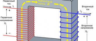
In electrical engineering, devices and equipment are systematically tested for resistance to electrical and dynamic loads. One such test is the transformer short circuit test. During the test, the current in the primary winding remains at its original value, and an artificial short circuit is created in the secondary winding. This event makes it possible to determine the rated current in the secondary winding, the power loss of the conductors, and the magnitude of the potential drop in the internal resistance of the transformer device. No-load and short-circuit experiments allow us to establish not only electrical, but also magnetic losses.
Purpose of short circuit experience
The no-load open circuit test is performed to determine the core losses without current load.
The essence of the test is that the high voltage winding remains open while the output winding is connected to the consumer's normal network. The necessary measuring instruments are also connected there - a wattmeter, an ammeter and a voltmeter. As a result of this connection, the external voltage that is applied to the device slowly increases from zero to its nominal value.
For this purpose, an additional autotransformer with sliding contacts is connected to the circuit.
The readings of all devices are recorded at the moment when the testing voltage reaches the required value in the output circuit. The physical essence of the measurement results is as follows:
- The ammeter shows the value of no-load current, the value of which is very small and hence the voltage drop can be neglected.
- The input power is indicated by a wattmeter. But the other side of the transformer is open, therefore, there is no output power, and the indicator on the wattmeter consists only of the values of power losses due to the degree of saturation of the core material and losses in the wires.
- A high-resistance voltmeter is connected through the external winding of the device. The high voltage winding is treated as an open circuit since the current through the voltmeter is negligible.
- The test results are highly accurate due to the low no-load current values and the absence of losses in the elements of the electrical circuit. Therefore, the wattmeter readings are guaranteed to determine the total losses in the core.
Types of short circuits in transformers
When a short circuit occurs, the transformer comes close to its maximum operating mode. In this case, some voltage is supplied to the primary winding, and the secondary winding is closed.
A transformer short circuit can be emergency or test. In the first case, a dangerous situation arises during the operation of the device, when it is connected to the rated primary voltage. A short circuit current appears in the windings, many times higher than the nominal value, and the device fails. As a rule, the main parts burn out and the whole circuit simply falls apart.
It is possible to avoid such negative consequences with the help of protective equipment - circuit breakers, fuses, relays, etc. It switches off as quickly as possible from the side of the primary winding and thereby preserves the device from destruction.
In the test mode, known as the short circuit test, a similar situation is created artificially. For this purpose, a reduced voltage is applied to the primary winding. At the same time, the currents in each winding do not exceed the nominal limits. This experience allows us to accurately determine the most important parameters and characteristics of the transformer device. Each of the short circuits should be considered in more detail from the point of view of its physical effect on the transformer.
How is it carried out?
For the high-voltage winding, the nominal no-load value is set. It is set according to the recommended phase angle values (sinΦ0 and cosΦ0; the index indicates that the transformer power is determined in no-load mode).
Next, according to the voltmeter readings, the parameters of the shunt equivalent circuits are measured. They are low voltage windings, so open circuit testing establishes both the core loss and shunt parameters of the equivalent circuit.
The correct test setup assumes that the transformer is in short-circuit mode at low voltage. A wattmeter, voltmeter and ammeter are connected on the high voltage side. The signal is applied to the power circuit and increases from zero until the ammeter reading is equal to the rated current. At this moment, readings from all instruments are taken, and the ammeter will show the value of the primary equivalent of the full load current, and the wattmeter will show the power loss in the conductors and core.
What to do if the measured short-circuit current is too low?
Let's say we measured it with a device and got the value of the short-circuit current in the socket (as a rule, the measurement is carried out at the most remote point). How can you tell if this current is too low? This is assessed by the criterion of guaranteed operation of the electromagnetic release of the circuit breaker in the measured circuit. It is logical that for this the short-circuit current must be greater than the upper limit of the tripping range. Let me remind you that for characteristic “B” the spread is 3…5 In, for “C” – 5…10 In, for “D” – 10…20 In. To be more precise, let’s turn to the PUE (clause 7.3.139):
7.3.139. In electrical installations up to 1 kV with a solidly grounded neutral, in order to ensure automatic shutdown of the emergency section, the conductivity of the neutral protective conductors must be selected such that, in the event of a short circuit to the housing or neutral protective conductor, a short-circuit current occurs that is at least 4 times greater than the rated current of the fuse link of the nearest fuse and at least 6 times the current of the circuit breaker release, which has an inverse current characteristic.
When protecting networks with automatic circuit breakers that have only an electromagnetic release (without a time delay), you should be guided by the requirements regarding the short-circuit current multiplicity and given in 1.7.79.
As I understand it, the first part of 7.3.139 only talks about the thermal release - its rated current must be at least 6 times less than the short-circuit current. The second part of this paragraph, as well as paragraph 1.7.79, talks about the maximum shutdown time during a short circuit (0.4 s), which must be provided only by an electromagnetic release. At the same time, it is not clearly indicated on the choice of AV taking into account its shutdown characteristics.
Because of this vagueness of the wording, they use the rule set out in PTEEP (checking the operation of protection in a power system with a grounded neutral, clause 28.4), which states that when a short circuit to the neutral protective conductor occurs, the short-circuit current must be at least “1.1 the upper value of the operating current of the instantaneous release.”
That is, for a B10 circuit breaker, the short-circuit current at the end of the line that it protects must be at least 10x5x1.1 = 55 A. If a C25 circuit breaker is installed, the short-circuit current must be at least 25x10x1.1 = 275 A.
If the short-circuit current is less, the permissible response time is by no means guaranteed. What to do? There are two ways out:
- increase the short-circuit current, this requires the cost of laying a new supply line (at least its weakest link),
- reduce the rating of the machine (for example, 25 A to 16) and the letter of the shutdown characteristic (from “C” to “B”) to the detriment of the maximum load power.
Read in more detail why it is always preferable to put “B” rather than “C” for group machines.
Methodology for calculating voltage, losses and short-circuit resistance
Calculations are carried out in the following sequence:
- Both components of the no-load current are determined:
Iμ = I0sinΦ0 and Iw = I0cosΦ0.
- The values of reactive X0 and active R0 resistances in equivalent circuits that relate to the low-voltage winding are set:
X0 = V1 / Iμ and R0 = V1 / Iw.
Here V1 is the voltmeter reading on the low voltage winding.
- The final power value is calculated:
W1 = 2IμR0 and W2 = 2IwХ0
W = (W21 + W22)0.5
Less accurately, the power W can be determined directly from the wattmeter readings.
This is explained by the fact that the voltage applied to produce the full load current, although small compared to the rated one, is still present on the windings.
- The value of equivalent resistance Zeq of the transformer is determined:
Zeq2 = R02 + X02.
The data obtained corresponds to those relating to the high voltage side of the transformer. Thus, as a result of the short-circuit test, the losses in the conductors a, as well as its approximate equivalent and reactance, are determined.
As a result of analyzing the information obtained, it is possible to determine the dependence of losses on the no-load current and voltage on the secondary winding.
It is also important that the total losses of a transformer depend on its reactance, and do not depend on the values of the phase angle between voltage and current.
Physical processes during an emergency circuit
From a technical point of view, any transformer must necessarily be destroyed as a result of a short circuit and the action of high currents. The main reason is the insignificant resistance of the wires and windings, which is many times greater than the resistance of the connected load.
One should also take into account the sharp increase in temperature in the windings, reaching 500-600 degrees within 1-2 seconds. This is enough for them to burn completely. We must not forget about the mechanical forces that arise between the windings during operation and tend to move them in the axial and radial directions. These forces increase significantly with increasing current, which theoretically should lead to instant destruction of the transformer. However, in practice everything happens differently.
Transformer devices are able to withstand short circuit currents for a short period of time until the protection is triggered and they are disconnected from the network. Some additional resistance was identified that limits high currents in the windings. It is formed due to magnetic leakage fluxes emanating from the main flux and closing around the turns of the corresponding winding.
The magnitude and difference of this scattering is almost impossible to accurately measure, mainly due to the different paths used to close the magnetic fluxes. In this regard, its assessment is made by the effect it has on the current and voltage in the windings. A pattern was identified according to which, as the current in the windings increases, the magnetic fluxes also increase. In normal operating mode, they constitute an insignificant part of the main flow, since they are only partially connected to the turns. The main flow affects all turns of the windings without exception.
Thus, the action of additional resistance makes it possible to minimize short-circuit losses of the transformer. All negative parameters are reduced many times and do no harm. That is, the device itself is able to protect itself from high currents arising from short circuits. Such situations arise quite rarely, but you still need to prepare for them in advance, taking the necessary protective measures in a timely manner.
Examples of calculations
The variety of situations in which it is advisable to carry out a short circuit test is discussed in the pages of Voltland magazine.
The initial data for calculations are:
- UI voltage drop related to a specific device type. Typically, its values range from 4.5% (for devices with reactive power 300 ... 500 kVA) to 5.7% for more powerful types of products;
- Number of poles of synchronous motors, powered by a transformer (from 6 to 14);
- Limit power loss coefficient (set by the manufacturer and given in the instructions).
We assume that the potential is supplied step by step until the value of the full secondary load current is reached on the connected ammeter.
Let us present the results in relation to a three-phase transformer designed for a voltage of U = 480 V, with a reactive power of 100 KVA and a reactive voltage of 13800 V.
Total short circuit current in the secondary circuit:
I = 1000 / 1.732 × U = 1.202 (A).
When the voltmeter reading U1 = 793.5 V, the percentage of losses in the impedance values will be
ΔZ = 793.5 / 13800 = 0.0575.
Therefore, the loss percentage is 5.75%. This shows that in the event of a fault in the three-phase connection, a maximum short-circuit current will appear on the secondary winding, the value of which is:
Ikz = 1.732× I = 2.0903 (A)
Maximum fault current Imax at secondary terminals:
Imax = Is/Δ Z = 2.0903/0.0575 = 36.5437 (A)
Based on the calculated value of Imax, the characteristics of the means of protecting the unit from overload are selected, in particular, the main switch, which must be installed in the secondary winding circuit.
§ 6. ELECTRODYNAMIC FORCES IN TRANSFORMERS
General information.
The conductors of windings carrying current in the stray field are acted upon by electrodynamic forces, which create mechanical stresses in the windings and are partially transmitted to the structural elements of the transformer. During normal operation, these forces are small, but under extreme conditions, such as a short circuit, they increase hundreds of times and can easily destroy the transformer unless special measures are taken to protect it. Many assembly jobs directly affect electrodynamic forces. Sometimes the quality of assembly operations cannot be verified either by external inspection or by control of a testing station. For example, weak pressing of the internal winding can only be detected during operation, after several short circuits, one of which will be destructive for the transformer. Therefore, the assembler must know the causes of occurrence, the nature of the impact and ways to reduce electrodynamic forces.
Electrodynamic forces with uniform MMF distribution.
Rice. 5. Diagram of the action of radial and axial forces on the windings of a two-winding transformer (a - with the same height of the windings, b - with a shortened outer winding) and radial forces on the winding coils (c)
Rice. 6. Deformation of the internal winding due to the influence of radial forces: a - star-shaped shape, b - loss of stability
In Fig. 5, a shows the windings and directions of action of internal Foc1 and Foc2 and external forces Foc1 and Fp2 with a uniform distribution of mf. Axial forces (determined by the radial component of the stray field) tend to reduce the height of the windings, radial forces (determined by the axial component of the field) tend to compress the inner and break the outer windings (Fig. 5, b). From the stray field induction distribution diagram (see Fig. 3, a) it is clear that the greatest axial forces bending the winding wires in the vertical direction occur in the end coils, where the radial field induction is greatest, and the axial forces not only bend the wires and coils, but also compress the gaskets between them. In this case, the maximum compressive forces are experienced by the gaskets in the middle of the winding, since the sum of all axial forces acting on all the coils of the winding is transferred to them. Radial forces are distributed evenly around the circumference of each coil (Fig. 5, c). The greatest forces are found in the coils in the middle part of the windings, where the axial field induction is greatest. In the end coils, somewhat smaller forces act, since the induction of the axial field at the ends of the windings is 0.7-0.8 of the greatest, however, the total effects on the wires of the end coils of the axial and radial forces are significant. The forces acting on the internal winding compress it, trying to “shorten” the length of the winding wires (Fig. 5, c). If the resulting stress in the winding is greater than the yield strength of the wire material, then residual deformations appear and the winding is destroyed, acquiring a typical star-shaped shape (Fig. 6, a). Sometimes residual deformations can take a different form: in one span the winding deflects inward, and in the adjacent span outward; such deformation is called loss of stability (Fig. 6, b). Radial forces acting on the outer winding tend to stretch its wires. They are especially dangerous for screw windings, as they can “unwind” them and “tear off” the ends, so these windings are rarely placed outside and special measures must be taken against possible “unwinding” of the turns. Electrodynamic forces with uneven MMF distribution. Different heights of the windings (see Fig. 3, c and 5, b), encountered in the practice of assembly work, lead to an uneven distribution of the MMF and a sharp increase in the maximum (“peak”) of the radial component of the stray field, while external forces arise that have not only radial, but also axial components, complementing their own axial forces. External axial forces are always directed in such a way as to increase the asymmetry that created them. External axial forces are frequent causes of accidents, therefore, when assembling transformers, it is necessary to strictly monitor the correct location of the windings on the rod, avoiding mismatch of the axes and heights of the windings.