What is a solar inverter for?
The grid-tied solar inverter is used in full-featured solar systems to convert DC to AC while increasing the voltage. Let's take a closer look at why you need an inverter for solar panels for 12 volts.
The panels convert the energy of sunlight into electric current, which is supplied to the battery through the controller. It accumulates charge and releases it as needed, while simultaneously replenishing the deficiency from solar modules. However, only a few consumer devices can use energy from batteries, since batteries produce low-voltage direct current - 12, 24 or (rarely) 48 V.
A voltage converter for solar panels is needed that can convert these indicators into standard values similar to network values. This task is performed by an inverter for solar panels, which receives 12 (24, 48) V DC from the batteries and supplies the usual 220 V AC to consumers.
The most common are conventional converters, the power of which is in the range of 250-8000 W. The dimensions of such devices depend on the load size, since the power is provided by additional components in the inverter design.
Device Features:
- Efficiency (on average) - 94%, maximum value reaches 99%
- complete absence of radio interference
- stabilized output voltage
- low harmonic distortion
- operating temperature affects quality, so it is necessary to ensure the widest possible range
- presence of overload protection
- losses in idle mode are minimal
- protection from moisture and mechanical damage
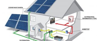
The absence of an inverter sharply limits the capabilities of solar panels. They can only charge batteries, provide power for low-voltage lighting or other specific devices. Solar inverters for the home allow you to get maximum efficiency from the panels and provide power for any household technical devices.
It is noteworthy that by connecting three inverters in a cascade, you can obtain a three-phase voltage with standard parameters, which can become a source for powerful electric motors and other installations.
DIY solar energy at home
Independent production of a battery based on solar panels, suitable for the needs of private households, seems to be a realistic endeavor only within the framework of modest projects.
A solar battery, assembled independently from silicon wafers, laid out in direct sunlight, is ready to be tested for the presence of voltage
For example, making a solar battery with your own hands to recharge a small battery, the energy of which is used to power two or three low-power (6 - 12 volt) flashlights.
For such projects, installations are made that produce a voltage of no higher than 20 volts at a current of no more than 1 A. Let's consider one of the possible options for creating a solar battery with similar performance characteristics.
To implement the project you will need:
- Wafers of silicon photocells.
- Electric soldering iron.
- Soldering tin.
- Ethanol.
- Pine rosin for soldering.
- Electrician's tool.
- Auxiliary electronic components and modules.
Prepared parts for assembling a home (country) solar panel.
Each of the elements is an individual source of energy. They need to be combined. The easiest way to purchase photocell (silicon) wafers is ready-made. Quite suitable designs of different sizes are sold at an affordable price. Offers are also available on the domestic Market:
An electrician who is familiar with electronics usually has a tool by default. Auxiliary equipment will require a battery charge regulator and an inverter.
Assembling a solar battery: step-by-step instructions
The step-by-step assembly of a solar panel generator looks something like this:
- Soldering individual plates with photocells into a single solar battery.
- Checking the operation of the assembled battery with a measuring device.
- Laying panels inside the protective structure.
- Connecting the assembled battery through the charge controller to the battery.
- Converting battery energy into the required voltage.
Soldering individual panels into a single battery is a painstaking job that requires soldering skills and attention. The complexity of the actions for the assembler is due to the fragile design of the silicon wafers.
Soldering on the plates is carried out carefully with a soldering iron of suitable power, having previously sharpened the tip at an angle of 45 degrees, using high-quality solder
It is recommended to connect the plates to one another using flat ribbon conductors. The goal is to minimize the conductor resistance as much as possible. Soldering areas should be pre-treated with ethyl alcohol. It is recommended to solder with minimal use of rosin and tin.
Having completed the soldering, you need to check the structure for functionality. This procedure is done in the usual way, using a measuring device - a tester (pointer, electronic).
Checking the performance of a do-it-yourself solar battery using a conventional digital instrument for measuring voltage, current, resistance
On the output conductors, the output voltage and current are measured under conditions of maximum and minimum illumination of the canvas. With high-quality soldering of all plates and without the presence of defects, the result is usually positive.
Battery charge controller
A solar power installation will become more reliable and safer if a battery charge (discharge) controller is included in its circuitry. This device can be purchased ready-made.
But if you have a knack for electronics and a desire for perfection, it’s not difficult to make a charge controller yourself. For reference, you can clarify: two types of such devices have been developed:
- PWM (Pulse Width Modulation).
- MPPT (Maximum Power Point Tracking).
If translated into Russian, the first type of device operates on the principles of pulse width modulation. The second type of device is designed to calculate the so-called maximum power point.
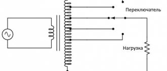
In any case, both circuits are assembled on a classic element base, with the only difference being that the second devices have more complex circuit designs. Charge controllers are included in the system as follows:
Classic block diagram of switching on a charge controller: 1 - solar panel; 2 — battery charge/discharge controller; 3 - battery; 4 - voltage inverter 12/220V; 5 - load lamp
The main task of the battery charge controller of a solar power installation is to monitor the voltage level at the battery terminals. Preventing voltage from going beyond the boundaries when the operating conditions of the battery are violated.
Thanks to the presence of the controller, the battery life remains stable. Of course, in addition to this, the device monitors temperature and other parameters, ensuring the safety of the battery and the entire system.
To assemble an MPPT controller with your own hands, you can take a lot of circuit solutions. There are no problems in finding circuitry, you just need to make a corresponding request in the search engine. For example, you can assemble a controller based on this, simple at first glance, block diagram:
Based on this block diagram, a fairly effective and reliable battery charge monitoring device is assembled using MPPT technology
However, for domestic purposes, a simple PWM controller is quite sufficient, since household power plants, as a rule, do not use massive solar panels. For controllers of the MPPT type, a characteristic feature is that they work with high-power panels.
At low powers they do not justify their circuit complexity. For the user, the purchase of such devices results in unnecessary expenses. Therefore, it is logical to recommend a simple PWM device for home use, assembled by yourself, for example, according to this scheme:
Schematic diagram of a simple PWM controller for a home solar installation. Works with 17 volt panel output and regular car battery
Solar battery: inverter circuit
The energy received from the sun is accumulated. At home, a standard car battery (or several batteries) is usually used to store energy.
The battery voltage and current are quite sufficient to power low-power household appliances designed for a voltage of 12 (24) volts. However, this option is not always suitable.
Therefore, in addition to the assembled structure, an inverter is connected - a device that converts the battery voltage into an alternating voltage of 127/220 volts, suitable for powering household appliances or household appliances.
Finding a suitable inverter circuit is not difficult. There are many ideas on this matter. Traditionally, the inverter circuit includes the following components:
- semiconductor solar panel,
- integrated circuit type SG3524 (charge regulator),
- battery,
- integrated circuit for controlling MOS transistors,
- power MOSFETs,
- transformer.
The block diagram of the regulator paired with an inverter looks something like this:
Block diagram of a battery voltage regulator in association with a voltage inverter-converter for a solar power plant
Solar panel protective structure
A solar battery assembled from fragile silicon wafers must be additionally protected from external influences. The protective case is made from a transparent material that is easy to clean.
Polyurethane or aluminum frame corners and transparent organic glass are just right. There is no point in explaining the intricacies of assembling the protective housing. This is a simple assembly, assembled with your own hands using a set of household tools.
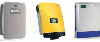
Types of inverters for solar power plants
There are several types of network inverters, differing in some design features and purposes. When assembling a complex of solar panels, various options are used, requiring the owner to correctly understand the specifics and features of their operation. First of all, inverters are distinguished by the shape of the output signal:
- sinusoidal
- rectangular
- pseudosinusoidal
Sinusoidal
The most preferred design option is a sine wave solar inverter . It is capable of producing the highest quality signal shape, optimal for all household appliances, technical and electronic devices.
Rectangular
Square-wave inverters are the cheapest, but they are recommended for use only for simple lighting fixtures. Many types of household appliances cannot operate from such sources.
Pseudo-sinusoidal
Pseudo-sinusoidal devices are a compromise between the first and second types, capable of working with any device. However, it is better not to use them when working with some sensitive types of consumers. In addition, interference and noise may occur from pseudo-sine wave inverters.
In addition, there are inverters designed to operate in different conditions. Let's take a closer look at them:
Network
Network inverters are used when users simultaneously connect to a centralized power supply network. According to the original plan, the inverter provides power to consumers and switches them to network consumption when the battery charge drops below normal.
Typically, grid energy is used during the daytime, when solar batteries are charging. At night there is a transition to autonomous power supply until the battery charge is exhausted. During the daytime, it is possible to release energy to the network if the battery charge is full. This function is also used if the power of solar panels significantly exceeds the needs of the house.
Abroad, there are programs and tariffs where the energy supplied is taken into account and paid to the owner of the solar battery. In our country there are no such opportunities yet, so network inverters for solar power plants are used only to power consumers and switch the energy supply mode.
This type of device is considered the most successful because it works intermittently and has high durability. Its disadvantage is the need to have a parallel connection to a centralized source.
Autonomous
An autonomous solar inverter is a converter that converts battery current into standard alternating voltage. It works in constant mode, there is no external support. Installed between the battery pack and the end consumers of electricity. If an autonomous type inverter fails, the power supply to household technical devices is cut off.
This scheme involves high loads, so the inverter power is selected with a certain margin. In addition, it is necessary to ensure inverter parameters that exceed the starting current of the most powerful consumer. This is important because the peak value can damage the device.
For example, a refrigerator or air conditioner at startup exceeds its operating capacity by 10 times, so it is necessary to have a certain reserve. Before purchasing, you should calculate the total power of all consumers and take into account peak starting loads. In addition, it is necessary to add a margin to compensate for the drop in output power over time.
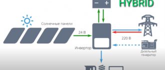
Hybrid
Hybrid or multifunctional inverters combine in their work all the capabilities of networked and autonomous devices. They are considered the best choice, but their cost often forces users to consider other options.
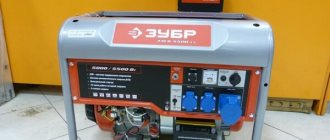
Solar inverter Sila 3000
One of the most popular devices is the Sila 3000 hybrid solar inverter, reviews of which indicate high performance capabilities. For example, with a rating of 2.4 kW, these inverters are capable of delivering 3 kW for a short time without negative consequences for themselves. When peak startup loads occur, Sila 3000 hybrid solar inverters can withstand operating mode changes. Despite the fact that they are made in China, the durability and reliability of the devices are assessed very positively by users.
Rating of inverter models
Below is a rating of the best inverter models for converting constant solar energy into variable energy for domestic purposes. Before purchasing, carefully read the technical characteristics of each, taking into account the above recommendations.
MAP HYBRID 243X3
This is a three-phase device that has the following set of characteristics:
- power 9 kW;
- total recommended power 100 V;
- peak value 15 kW;
- frequency 50 Hz;
- temperature minus 25 – plus 50;
- size 630x370x510mm;
- weight 61.5 kg.
This is a type of hybrid inverter that works autonomously with both solar stations and the household network. MAP HYBRID is characterized by a high efficiency value. If one of the phases fails, the device continues to work, and the generation function is transferred to the battery, while the operation of the solar battery does not change in any way, and at the output you still get a maximum of 380 V.
MAP HYBRID 2445X3
The principle of operation of this inverter is no different from the previous one; here it is also possible to accumulate energy in the battery and use it in the event of a failure of one of the phases or all three. The difference between the device lies in the technical characteristics:
- total power 24V;
- maximum power 13.5 kW;
- peak power 21 kW;
- nominal power 8 kW;
- frequency 50 Hz;
- recommended battery capacity min -1200 and 600 A/h;
- temperature range -25…+50;
- size 630×370×501mm;
- weight 74.7 kg.
MAP HYBRID 246X3
This model is ideal for both battery and home network use. Has the following indicators:
- maximum power 18 kW;
- peak power 27 kW;
- rated power 12 kW;
- dimensions 720/370/510 mm;
- weight 94.8 kg.
At the output you will also receive the maximum value of the network voltage - 380 V. In the event of a failure or loss of current in one of the phases, the battery is connected for backup. The transmission frequency is completely adjusted to the existing one in the network. Once peak power is reached, operation will continue for another 5 seconds.
Hybrid solar inverter
4 MAP HYBRID 249X3
Despite the fact that this three-phase inverter is inferior to the previous one, some of its values are an order of magnitude higher, but this is primarily due to its increased weight. In terms of its other functional characteristics, it is completely identical, it also produces up to 380V and can work without interruption even if one of the phases is disconnected.
- peak power 27 kW;
- maximum power 27 kW;
- rated power 18 kW;
- size 720/410/560 mm;
- weight 122.1 kilograms.
5 MAP HYBRID 4845X3
It occupies an honorable fifth place and is lightweight, despite its fairly good quality and technical characteristics. What is especially important is that it works with a maximum efficiency of up to 95%.
- peak power 21 kW;
- rated power 9 kW;
- highest power 13.5 kW;
- operating temperature -25…+50;
- size 630x370x510 millimeters;
- weight 59.3 kilograms.
The inverter converts the voltage from one phase to three phase. Works great with a solar station and alternating current with a voltage of 220V. It also has the ability to generate energy in the battery and use it when the battery is disconnected. This inverter can be used for any purpose, both to provide lighting, regardless of the area and the number of lighting fixtures, and to operate electrical appliances.
Review of popular models
Let's consider several models of inverters for solar panels, which are considered the highest quality and most reliable:
MAP "Energy"
Products of the Russian MAP "Energia". Several varieties of single- and three-phase devices with a sinusoidal output voltage graph are offered. They have a built-in battery charger. There are different power options from 800 W to 20 kW (withstands a peak short-term load of 25 kW).
Schneider Electric
Schneider Electric, based in France, produces Conext inverters. They can work in difficult conditions, including outdoor installation. The range includes models with a power of 3-20 kW.
TBS Electronics
The Dutch company TBS Electronics offers Poversine sine wave inverters of different powers - from 175 W to 3500 kW. They have multi-stage protection and are able to withstand starting loads tens of times higher than the rated values.
The list of manufacturers of reliable and high-quality inverters can be continued for a long time. The choice of a suitable device must be made based not only on the name of the company, but also on other criteria.
Inverter operation
The inverter is one of the three basic elements of a solar power plant. The system consists of a converter, a solar panel and a battery. The classic operating scheme of a solar station is that the solar energy received by the battery in the form of direct current is spent on charging the battery. When the need for additional power arises, the converter begins to take energy from the battery, converting it into alternating current.
Inverter (IV) is a semiconductor device. During the daytime it is connected directly to the solar panel. At night, the device switches to batteries.
Important! The inverter is selected based on the maximum load power at peak activity. For simple models, take the calculated value according to the nominal value indicated in the device passport.
Operation of a solar power plant
Inverter selection
Let's look at how to choose a grid-connected solar inverter. The best option is to purchase a ready-made set of devices with selected parameters. Selecting a separate inverter is a task that is quite difficult for an untrained person. However, you often have to buy a device for a ready-made set of solar modules.
It is customary to be guided by the following indicators:
- input voltage and power matching
- methods of protection
- Operating temperature range
- presence of several modes
- Efficiency
When choosing network inverters for solar panels, you need to make a simple calculation. The power of all consumers is added up, and some reserve is added to ensure peak loads.
It must be borne in mind that many consumers create an increased starting load at the time of startup. If the inverter power is selected incorrectly, peak values will quickly damage the device. In addition, you need to pay attention to the permissible temperature values, since the inverter is sensitive to this indicator.
Criterias of choice
Choosing an inverter for installing a solar power plant is very important. The future operation of the entire system depends on which device is connected. There are several basic technical parameters that you should consider before choosing a suitable inverter.
- Power - the operating power of the entire power plant depends on this value. All the current passes through the inverter, which is then supplied to the room and powers the connected devices. The power rating indicates the permissible load that the inverter can experience, both during connection and throughout operation. The power is selected based on the following criteria: a 12 V inverter is suitable for a system with a power of up to 600 W, a 24 V device is installed with a power of 600-1500 W and 48 V with a power of over 1500 W.
- Possibility of exceeding the rated load. This is extremely important for appliances such as washing machines, refrigerators and air conditioners that contain electric motors. When starting them, a little more electricity is required, and if the inverter power is not enough for this, then the devices may, at best, not start, and at worst, they may fail.
- The type of output signal - a sinusoidal shape - is responsible for the ability to connect any equipment to a specific inverter model. The advantages are that this type of output signal protects electrical appliances from voltage surges.
- Efficiency is determined by the amount of empty energy that the device spent, for example, on itself. This figure should not exceed 5-15%, otherwise the installation of solar panels will be unprofitable and their operation ineffective. The efficiency of the bulk of inverters supplied to the market is 85-95%.
- Single-phase or three-phase inverters. The former are cheaper than the latter, but they are only suitable when the power consumption is less than 10 kW. The voltage of such energy converters is 220 V, frequency 50 Hz. Three-phase inverters have a wider choice in terms of voltage - 315 V, 400 V, 690 V.
- Number of inverters in the system. How many devices to install depends on the power of the solar panels. If it is no more than 5 kW, then one inverter is enough. With more power, two devices will be required. The required quantity is determined on the basis that for every 5 kW one inverter is needed.
- The mass of inverters primarily indicates their quality. Good devices cannot be lightweight. But some manufacturers offer low-grade converters for solar batteries. They do not have a transformer. This is fraught with the fact that if the current increases, the entire system may fail.
When choosing an inverter for solar panels, you need to take into account its power.
In addition, different models have a number of additional options and protective elements. This could be a built-in socket, LCD display, charger, etc. If you have problems with electricity, it is better to choose an inverter with short circuit and overload protection.
You also need to consider the starting power of the converter. It is used for only a few seconds, but is very important for starting the device. After this, the inverter begins to operate normally. The starting power should be 1.5 times the rated power.
Connecting the inverter to the solar battery
It is necessary to prepare a cable of the appropriate cross-section that can withstand all possible loads. It is necessary to take into account that the length of the connecting cable between the solar panels and the inverter should not exceed 3 m. If consumers are located far from the modules, extend the high-voltage arm - a 220 V cable. Consider the procedure for connecting the device to a set of solar equipment:
Scheme
The simplest diagram for connecting an inverter is in the gap between consumers and batteries. This option is used for standalone devices.
The most complex scheme is for networked or hybrid devices. In parallel with the battery, the mains voltage is connected (to the corresponding contacts), and the load is immediately connected. An additional pair of contacts is intended for a redundant system (backup lighting, emergency power, etc.). The choice of circuit depends on the purpose and design of the inverter, as well as the availability of a connection to a centralized network.
Stages
The process of connecting devices does not cause any difficulties. All contacts are named, the main task is not to confuse them in a hurry. First, the entire kit is assembled - panels, controller, battery. After this, connect the inverter and check its functionality. Any errors found are immediately corrected. When you are completely confident that all connections are correct, connect the payload - power supplies. From this moment on, the solar panels are considered to be put into operation.
How to choose an inverter
Important parameters of this device
- The power it can handle.
- Number of simultaneously connected panel lines.
- Operating frequency
- The efficiency factor directly affects the performance of the entire station.
- Equipment weight as an indicator of its quality.
Now about all this, and more, in more detail!
Before you start choosing such equipment, you need to decide on the type of solar power plant you have and its purpose.
1 Autonomous power plant
.
Your power plant is not connected to an external electrical network and you receive all electricity only from the panel. In this case you need an off grid
.
Depending on their power, autonomous inverters are divided into single-phase and three-phase, and can also convert different DC voltages ranging from 12V, 24V, 48V, 96V, etc.
This is the cheapest version of this equipment; the cost, depending on the power and country of manufacturer, is $25-600.
2 Network power plant
. Your solar power plant can work in conjunction with the central electrical grid, but does not have batteries.
The inverter regulates the extraction of electricity from the network, but not from the batteries
, if the panels do not produce enough.
It can also send excess generated electricity back to the central grid, for example if you want to sell it at a feed-in tariff. Such equipment has the on grid
.
In addition to its main function, this equipment has a number of capabilities:
- regulate the voltage frequency,
- set 220 V,
- regulate the current amplitude,
- protect equipment from overheating,
- protect the network from short circuits.
- display information on the screen of a phone, tablet or PC monitor via Wi-Fi.
The cost of such equipment is much higher and ranges from 200-20,000 dollars.
It is worth noting that the price directly depends on the power of the device, for example, a 3-6 kW inverter will cost $2000, for 1000 kW it will cost about $20,000. For a home station, 5 kW is quite enough.
3 Battery-network
. Your power plant provides electricity to all appliances, and sends the excess to batteries, which release the accumulated charge at night or when the batteries cannot cope with the load.
Stages of work
Frame
Before you start making a solar panel with your own hands, you need to build a frame for it. It protects the battery from damage, moisture and dust.
The body is assembled from moisture-resistant material: plywood coated with a moisture-repellent agent, or aluminum corners to which plexiglass or polycarbonate is glued with silicone sealant.
In this case, it is necessary to maintain indentations between the elements (3-4 mm), since it is necessary to take into account the expansion of the material with increasing temperature.
Soldering elements
The photocells are laid out on the front side of the transparent surface, so that the distance between them on all sides is 5 mm: this takes into account the possible expansion of the photocells as the temperature rises.
Converters having two poles are fixed: positive and negative. If you want to increase the voltage, connect the elements in series, if the current - in parallel.
To avoid discharging the battery at night, a Schottky diode is included in a single circuit consisting of all the necessary parts, connecting it to the positive conductor. Then all the elements are soldered together.
Assembly
Soldered converters are placed in the finished frame, silicone is applied to the photocells - all this is covered with a layer of fiberboard, closed with a lid, and the joints of the parts are treated with sealant.
Even a city dweller can make and place a solar panel on the balcony with his own hands. It is advisable that the balcony be glazed and insulated. So we figured out how to make a solar battery at home, it turned out that it’s not difficult at all.
How to assemble a solar battery at home?
If, after studying the information presented above, the desire to start making a solar battery has not disappeared, you can experiment by creating and testing your own creation. Next, the assembly of a panel from monocrystalline wafers will be discussed in detail.
Monocrystalline wafer 78×156 mm with two current collector tracks on the front side. Symmetrically to them, on the back side of the plate, the busbar soldering lines are marked with shaped contact windows.
In the example shown, a home craftsman assembles a panel with dimensions of 750x960 mm, consisting of 36 rigid monocrystalline plates measuring mm. The plates are installed in four rows, with 9 photocells in each. A gap of about 10÷12 millimeters is maintained between the photocells.
Solar panels are installed on the balcony railing and also attached to its glazing. This installation will be relevant if the balcony is located on the sunny side of the house. The panel whose installation will be shown is highlighted with a red frame.
| Illustration | Brief description of the operations performed |
| To work, you will need, first of all, the plates themselves. The wizard recommends purchasing them with a reserve, since they may have different output voltage parameters, and from them you will need to select 36 pieces that have the values closest to each other. The busbar is a tinned copper strip, that is, already coated with tin, which simplifies its soldering. You will need about 10 meters of a narrow tire with a width of 1.6 mm and 2 meters of a wide one with a width of 5 mm. For electrical work, you need to prepare a regular 40 W soldering iron. soldering flux is rosin dissolved in alcohol, alcohol for degreasing surfaces for soldering and their subsequent cleaning from flux residues, cotton pads and swabs. In this case, acrylic glass 5 mm thick is used as the basis for mounting the entire module. For subsequent sealing of the photocells, the master decided to use durable colorless transparent polyvinyl chloride film ORACAL®751, which is often used to attach advertising to vehicles. | |
| A few words about why the tire width of 1.6 mm was chosen. Metal tends to expand when heated, and when cooled, accordingly, contract. On a solar battery, this process will occur constantly, that is, during the day the soldered busbars will increase in size, and at night - on the contrary, which is not particularly useful for the design. The master tested a tape with a width of 2 mm, and still chose a width of 1.6 mm. In terms of conductive qualities, these buses do not differ much from each other, and the narrower one is still less susceptible to linear deformation. | |
| Having prepared everything you need, it makes sense to first sort the plates. As mentioned above, despite the fact that this is one model, they can often have different indicators in practical work. And for the battery to operate harmoniously, the generated voltage values must be as close to each other as possible. For example, in this case, during the test it was discovered that photocells under equal conditions (under artificial lighting) can produce from 0.19 to 0.35 volts. It is better if elements that have the closest possible values, say, from 0.30 to 0.33 volts are collected in one panel. If one or two elements are installed in the complex, significantly different in output voltage, then they will create unnecessary resistance and will begin to overheat. Thus, plates that clearly fall out of the total mass are rejected. | |
| When installing the plates, a gap of 10÷12 mm will be left between them. It is needed so that the film that fixes the elements on the acrylic glass holds them on all sides. | |
| Next, you need to place two plates on the table at a distance of 10 mm, and use them to measure how long the narrow tires need to be cut. As you can see, on the outer side of the fastening plates there are two metal current-collecting strips, and on the reverse side of it, the fixation points are indicated dotted with windows. | |
| On the front side of the plate, it is necessary to retreat approximately 3 mm from its upper edge. | |
| On the back side of the second panel, the bus should also not reach the bottom edge by the same 2÷3 mm. | |
| After determining the length of one connecting bus, the remaining connecting elements are measured along it. For every two plates you will need two pieces of tire, that is, a total of 72 pieces are needed. When cut, the tires look as shown in the photo. It is not at all necessary to prepare all the segments at once - they can be cut as you go. However, if they are prepared all at once, it is recommended to collect them and secure them with an elastic band. This way they won’t get lost and won’t get in the way on the table. | |
| First, the busbars are soldered to the front side of all the plates. But before soldering, the metal current-collecting strips on the plates must be prepared by degreasing with alcohol. For this work, it is convenient to use cotton swabs - they are dipped in alcohol and passed over the strip. This process is necessary to improve the quality of soldering. | |
| The next preparatory stage is applying rosin flux to strips cleaned with alcohol. It is better if it is poured into an elastic container in the form of a marker (glue stick) with a soft tip. This will make it easier to work, if necessary, squeezing out and distributing the required amount of composition. | |
| The next step is to solder the busbars to the outside of the plates. The bus is placed on a metal contact strip and leveled. Next, holding most of the busbar, carefully pressing it against the strip, its upper side is fixed with a soldering iron at 20–30 mm in length. Additional solder is not used - a layer of tinning on the bus itself is sufficient. Now it is fixed and will not be able to move, so it will be quite easy to secure its remaining long side to the surface. | |
| To do this, the plate must be turned towards you with the opposite side, so that the long part of the tire is at hand. Holding the bus and pulling it slightly, carefully run the soldering iron over it, making sure that it does not slip to the side. Tinned tape is easily soldered to a properly prepared surface - it is enough to run a well-heated soldering iron over it once without haste. If burrs remain on the tape, they must be smoothed out immediately, since this side of the plates must be pressed against the acrylic glass. | |
| Having soldered both tapes to the plate, they must be wiped with alcohol using a cotton swab or disk. All remaining flux must be removed from the surface. | |
| In the same way, all 36 wafers, or only 9 solar cells, are sequentially prepared to assemble one of the four strips of the solar panel. Here each master does what is most convenient for him. | |
| Next, we will consider the assembly of prepared photocells into one strip. The remaining three strips of the solar panel are connected in the same way. | |
| First, a plate is taken that will be the first in the strip. It is placed face down on the table, along with the tires soldered to it. Then the solder strips, highlighted on the back side of the plate with contact windows, are treated with alcohol and then with flux. Next, stepping back from the edge by about 3 mm along a line passing through the windows, a section of the bus is laid and soldered to the surface using the same method as on the outside. The free ends of the buses should be located in the opposite direction relative to those soldered to the front surface - they will be needed when switching the entire series of elements into a common battery with wide buses. | |
| Now you need to connect the first and second plates of the row together. To do this, the ends of the bus bars soldered to the front side of the first plate must be brought out to the back side of the second plate. The plates are placed parallel to each other at a set distance (10 mm). For convenience, you can make markings on the desktop in advance, that is, make a kind of template for the relative position of the plates. | |
| The contact soldering points are treated with alcohol and then flux is applied to them. | |
| Now you can solder the busbars. To do this, also carefully, slowly, run a heated soldering iron over them. After finishing soldering both busbars, they also need to be wiped with alcohol to remove the remaining flux. | |
| Next, the third and all subsequent plates of the row are switched in the same way. The result should be four strips of 9 photocells, connected as shown in the illustrations. | |
| Ready-made, soldered rows of photocells are placed one by one on pre-prepared acrylic glass of the required size. A distance of 50÷60 mm must be maintained from the edges of the elements to the edge of the glass. The rows are temporarily fixed on the glass with short strips of transparent tape. | |
| The “golden rule” of sequential switching of DC power supplies: the plus of the previous element is connected to the minus of the next one - and so on. This rule is observed in the ranks. Now it is very important not to disturb it when laying rows in the battery. Thus, the sections of the first and third row tires protruding from the left must be soldered on the outer side of the panel, which in this case is turned towards the acrylic surface. In the second and fourth rows, the ends of the tires should protrude, fixed on the back light side of the plates. If you make a mistake, the serial connection will be broken and the battery will not work. | |
| As a result, the design of the laid panel should look like this. When all the rows are secured to the glass with tape, they must be combined into one system. | |
| The electrical connection is made according to the diagram presented. As a result, there will be a “plus” on top and a “minus” on the bottom. | |
| Wide busbars are used as connecting elements - this is clearly shown in the diagram above. The protruding ends of thin tires are soldered to them. After soldering, the excess should be cut off with pliers. | |
| This photo clearly shows the extreme point of bus commutation. Having completed the work, the panel must be checked for functionality using a tester, switching it to a voltmeter and setting the probes to plus and minus. | |
| The panel can be checked first on the desktop - there will not be large indicators, but the assembled panel will demonstrate that it is “live”. And then you can test it by taking the battery out into the sun. | |
| The multitester probes are attached to the outer positive and negative tires. | |
| Even in cloudy weather at idle, the battery produces 19.4 volts - this indicates that the panels are connected correctly. | |
| There was no sun at the time of testing, and the current was small, only about 0.5 amperes. But even in cloudy weather, the battery produces about 10 watts of energy. | |
| At the same time, it is recommended to check the plates for overheating - it’s easy to feel it with the back of your hand. If individual plates against the general background are clearly overheating, then it is advisable to replace them immediately - this is not difficult to do for now. | |
| If the battery works normally, then you can finally seal it - roll it in film. The service life of this film is seven years, but as practice shows, it functions well even longer. The film has an adhesive layer covered with a protective backing, which is removed as the coating is glued to photocells and acrylic glass. | |
| The first thing to do is to lay the film on top of the structure and align the edge from which it will begin to be glued. The quality of gluing of the entire canvas depends on how aligned the edge is. Complete sealing must be achieved, without folds or voids, since the film is designed to reliably protect photocells from any external influences. | |
| Next, you need to carefully separate the protective layer from the film along the entire edge, by about 40 mm, immediately securing it to the glass. | |
| This operation is carried out very carefully; when gluing, the film is leveled and smoothed. Here you need to remember that peeling off and leveling a certain section of the film will no longer work, so you need to do the job efficiently right away. The film should not be stretched, but at the same time it should not bunch up. | |
| The protective backing is folded down and gradually removed as it is glued. Having released 20÷30 mm of the film, it is smoothed onto the photocells and the gaps between them, that is, onto the acrylic glass. | |
| The process of rolling the battery in film is long and painstaking, so you need to be patient and do it slowly. If the film still gets wrinkled or goes to the side, it cannot be peeled off, as the photocells will be damaged. In this case, it is necessary to cut out and paste an additional fragment on top of the already attached film. The main thing is to cover the entire surface of the battery. This illustration shows the edge of the panel rolled up in film. It is clearly seen that perfect smoothness is not required, the main thing is a tight fit of the film over the entire area. | |
| Once the film is pasted, you can test the finished panel. To do this, you need to take the battery out into the sun and connect the tester to it again. | |
| As you can see, the battery produces an output voltage of almost 20 volts. Then the short circuit current is checked - it was 3.94 amperes. And this is neither more nor less – almost 80 watts. | |
| To check under load, a 24 V light bulb was connected to the battery through an ammeter. The result in the photo is that it burns, although not at full intensity, but quite brightly. |
Many craftsmen, in addition to glass and film, also use battery framing, placing it in a rigid frame. This gives the structure the necessary strength and increases its reliability.
If you plan to assemble and use several solar panels, then they are connected either in series - to increase the output voltage, or in parallel - this way you can achieve higher current and total power
The panel complex is connected through a controller to a battery - an energy storage device, and from it distribution is made to points of consumption, directly or through an inverter.
Find out how to make a solar collector with your own hands from our new article on our portal.
* * * * * * *
So, as you can see from the information presented, the battery can be assembled with your own hands. You will need some knowledge of electrical engineering and installation, perseverance and attentiveness.
Another thing is that you should first very carefully weigh the expected effect of the battery and the cost of components and all equipment necessary for the system. How profitable will the system be, especially taking into account local climatic conditions? Will its creation simply turn into a “toy” for an active middle-aged man?
Perhaps the video below will answer some questions about this:
Installation example of a single-phase inverter
First, let's consider a single-phase system in practice, and then move on to a three-phase one.
I recently told you the difference between single-phase voltage and three-phase voltage.
The appearance of the mounted inverter is shown at the beginning of the article. Its power in this case is 5 kVA, there are models for other powers.
And here is how the inverter interface with all the inputs, outputs and controls works:
Solar single-phase battery inverter for home. Connection terminals
The batteries must be connected via a circuit breaker:
Circuit breaker for connecting the battery to the inverter
Through these terminals, the battery is charged from the sun or from the network and releases energy for conversion:
Terminals for connecting batteries to the inverter
Connection to the electrical panel - via cable VVG4x4, protective conductor separately:
Connecting 220V input and output to a solar inverter
If the length of the cable line is more than 10 meters, then it is better to use a cable with a cross-section of 6mm² to avoid unnecessary losses in the cable.
Another important note! Unlike stabilizers, the input and output neutrals of the inverter are galvanically isolated. And if you connect them, the inverter will not work!
In the home panel, I unscrewed the wires (black SIP 2x16) from the street from the two-pole input circuit breaker, and applied street voltage through the terminal block to the inverter input. And from the output of the inverter - to the input of that same machine:
Remodeling a home electrical panel to connect a solar inverter
As a result, the power system installed under the stairs looks like this:
Installation of a home energy system using an Ecovolt solar inverter
4 batteries are used, each with a voltage of 12V and a capacity of 200 Ah.
After connection, you need to configure the inverter according to the instructions.
The instructions for the solar inverter can be downloaded at the end of the article.
This is what the inverter screen looks like during normal operation:
Ecovolt solar inverter operation. The load is powered from the street via a bypass, while the battery is charged at the same time
For various operating modes and settings, there is an informative picture on the screen that will be understandable to an untrained user.
And here’s what will appear on the screen if the voltage from the street disappears:
Inverter operation with batteries
In this case, as when working from solar panels, the solar inverter produces a stable sinusoidal voltage of 230V, as required by the standard.
Main technical characteristics
Inverter for welding
It is necessary to select an IV, commensurate its capabilities with the installation conditions in a particular electric current supply circuit. The choice is directly related to the technical characteristics of the device:
- The power should be equal to the total load from household appliances and various electrical devices. In this case, you need to add 15-25% to the parameter value in case of peak electricity consumption;
- The type of output signal, which is displayed in the form of a sine wave, affects the connection of certain electrical equipment to the load. Cheap models with a quasi-sine waveform can cause complications in the operation of sensitive equipment in terms of signal quality. These are boilers, electric pumps and various electronic devices;
- The input and output voltage is related to the characteristics of the solar panels. The batteries produce current at voltages of 12, 24 and 48 volts. The voltage at the inverter output can be 220 or 380 V.
- The type of protection is associated with a specific IW model. High-quality inverters are equipped with protection against short circuits and voltage surges;
- Additional features depend on the converter class. These may be options such as the presence of an LCD screen, charger, etc.