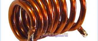
The picture above shows a single layer inductor: D
c is the diameter of the coil,
D
is the diameter of the mandrel or frame of the coil,
p
is the winding pitch of the coil,
d
is the diameter of the wire without insulation and
d
i is the diameter of the wire with insulation
To calculate the inductance LS, use the formula below from the article by R. Weaver, Numerical methods for calculating inductance:
Here
D
- diameter of the mandrel or coil frame in cm,
l
- coil length in cm,
N
- number of turns and
L
— inductance in µH.
This formula is valid only for a solenoid wound with a flat wire. This means that the coil is wound with a very thin tape without any gap between adjacent turns. It is a good approximation for coils with a large number of turns, wound with round wire with a minimum gap between the turns. The American physicist Edward Bennett Rosa (1873–1921) who worked for the US National Bureau of Standards (NBS, now called the National Bureau of Standards and Technology (NIST)) developed the so-called correction factors for the above formula in the form (see formula 10.1 in article by David Knight, David W. Knight):
Here L
S is the inductance of the flat helix described above, and
where k
s is a dimensionless correction factor that takes into account the difference between the self-induction of a coil of round wire and a coil of flat tape;
k
m is a dimensionless correction factor that takes into account the difference in the total mutual inductance of turns of round wire compared to turns of flat tape;
D
c is the diameter of the coil in cm, measured between the centers of the wires and
N
is the number of turns.
The value of the Rosa coefficient k
m is determined by formula 10.18 in the article by David Knight mentioned above:
Rosa coefficient k
s, taking into account the difference in self-induction, is determined by formula 10.4 in the article by D. Knight:
Here p
- winding pitch (distance between turns, measured at the centers of the wires) and
d
- wire diameter.
Note that the p/d
is always greater than one, since the thickness of the wire insulation is finite, and the minimum possible distance between two adjacent turns with very thin insulation, located without a gap, is equal to the diameter of the wire
d
.
Calculation methods
There are several basic ways to determine the inductance of a coil. All formulas that will be used in the calculations can be easily found in reference books or on the Internet. The whole calculation process is quite simple and will not be difficult for people with basic mathematical and physical knowledge.
Through current
This calculation is considered the simplest way to determine the inductance of a coil. The formula through current follows from the term itself. What is the inductance of the coil can be determined by the formula: L=Ф/I, where:
- L - circuit inductance (in Henry);
- F is the magnitude of the magnetic flux, measured in webers;
- I is the current strength in the coil (in amperes).
Finite Length Solenoid
The solenoid is a thin long coil, where the thickness of the winding is significantly less than the diameter. In this case, calculations are carried out using the same formula as through current strength, only the magnitude of the magnetic flux will be determined as follows: Ф=µ0NS/l, where:
- µ0 is the magnetic permeability of the medium, determined from lookup tables (for air, which is taken by default in most calculations, it is equal to 0.00000126 henry/meter);
- N is the number of turns in the coil;
- S is the cross-sectional area of the coil, measured in square meters;
- l is the length of the solenoid in meters.
The self-induction coefficient of the solenoid can also be calculated based on the method for determining the energy of the magnetic flux of the field. This is a simpler option, but it requires some quantities. The formula for finding inductance is L=2W/I 2, where:
- W is the magnetic flux energy, measured in joules;
- I is the current strength in amperes.
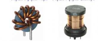
Toroidal core coil
In most cases, a toroidal coil is wound on a core made of a material with high magnetic permeability. In this case, to calculate the inductance, you can use the formula for a straight solenoid of infinite length. It has the following form: L=N µ0 µS/2 πr, where:
- N is the number of coil turns;
- µ—relative magnetic permeability;
- µ0—magnetic constant;
- S is the cross-sectional area of the core;
- π is a mathematical constant equal to 3.14;
- r is the average radius of the torus.
Long conductor
Most of these quasi-linear conductors have a circular cross-section. In this case, the value of the self-induction coefficient will be determined by the standard formula for approximate calculations: L= µ0l (µelnl/r+ µi/4)/2 π. The following notations are used here:
- l is the length of the conductor in meters;
- r is the radius of the wire cross-section, measured in meters;
- µ0—magnetic constant;
- µi is the relative magnetic permeability characteristic of the material from which the conductor is made;
- µe is the relative magnetic permeability of the external environment (most often the value for vacuum is taken to be 1);
- π—pi number;
- ln is the notation for logarithm.
Relationship between magnetic field strength and magnetic induction
General view of the magnetic field strength formula:
Н = I/(2*π*r).
Here H is the calculated value, I is the flowing current, r is the distance to the point whose field characteristic needs to be assessed. The unit of measurement of voltage looks like a quotient of the units in which current and distance are measured: ampere and meter (A/m).
For a solenoid containing n turns and having a length L , the expression will apply:
H = I*n/L.
Under vacuum conditions, the relationship between tension and induction values can be described as follows:
B = μ0*H,
where μ0 is a constant equal to 1.256*10-6.
With some coarsening, this relationship is also true for the air environment. When there is an object in the field zone, it is necessary to take into account the magnetic permeability of the substance from which it is made (μ). Then the ratio of quantities takes the following form:
B= μ* μ0*N.
For paramagnetic materials (for example, aluminum products) and especially for ferromagnetic materials (all types of iron and steel), the value of μ is large, which leads to an increase in induction, while for diamagnetic products (for example, copper) it is less than unity, which slightly reduces the flux density.
Based on the above expressions, you can create formulas for conductor products of various shapes:
- for a ring with radius R: B=(μ*μ0*I*n)/2R;
- for a straight cable of infinite length: B=(I*n*μ*μ0)/(2π x r);
- for a spiral: B=(I*n*μ*μ0)/L.
Single turn circuit and coil
The inductance of a loop representing a turn of wire depends on the amount of current flowing and the magnetic flux passing through the loop. For the inductance of the circuit, the formula determines the parameter, respectively, through the flux and current strength:
L=F/I.
The weakening of the magnetic flux due to the diamagnetic properties of the environment reduces the inductance.
The parameter for a multi-turn coil is proportional to the square of the number of turns, since not only the magnetic flux from each turn increases, but also the flux linkage:
L=L1∙N2.
In order to calculate the inductance of a coil, the formula must take into account not only the number of turns, but also the type of winding and geometric dimensions.
What is inductance
This term denotes the relationship that is established between the current strength in the conductor (I) and the created magnetic flux (F):
L = Ф/ I.
Given the basic definition, it is not difficult to understand the dependence of inductance on the properties of the environment, which influences the distribution of power lines. The dimensions and configuration of the conductive element have a certain significance.
Inductance is similar to mechanical inertia. Only in this case we are talking about actions with electrical quantities. This coefficient characterizes the ability of the component in question to resist changes in the current passing through it.
induced emf
Let us understand in detail what the concept of induced emf is. When a conductor is placed in a magnetic field and moves with the intersection of field lines, an electromotive force called induced emf appears in the conductor. It also occurs if the conductor remains stationary, and the magnetic field moves and intersects the conductor with lines of force.
When the conductor where the EMF occurs is closed to the external circuit, due to the presence of this EMF, an induced current begins to flow through the circuit. Electromagnetic induction involves the phenomenon of inducing an EMF in a conductor at the moment it is crossed by magnetic field lines.
Electromagnetic induction is the reverse process of transforming mechanical energy into electric current. This concept and its laws are widely used in electrical engineering; most electric machines are based on this phenomenon.
Quality factor
Quality factor is the ratio between reactive and inductive (active) reactance.
Active is an indicator of the natural resistance of a material. Reactive occurs if the effective value of voltage, current or capacitance changes.
The following equation is used for measurement:
Q=2∙π∙f∙L/R,
Where:
- π – Pi number equal to 3.14;
- F – frequency;
- R – resistance.
A problem may arise with the concept of “frequency”, because Many people do not know what an oscillatory circuit is. This is some kind of circuit in which there is a coil.
Typically, an oscillating circuit consists of a power source, an inductive element and a capacitor. The frequency is determined using Thomson's formula (also known as the resonant frequency formula).
The higher the frequency indicator, the “higher quality” the coil is considered.
Application of coils in technology
The phenomenon of electromagnetic induction has been known for a long time and is widely used in technology. Examples of using:
- smoothing out ripples and interference, storing energy;
- creation of magnetic fields in various devices;
- feedback circuit filters;
- creation of oscillatory circuits;
- transformers (a device of two coils connected inductively);
- power electrical engineering uses to limit the current during a short circuit. on power lines (inductors called reactors);
- limiting the current in welding machines - inductance coils make its operation more stable, reducing the arc, which allows you to get an even welding seam that has the greatest strength;
- the use of coils as electromagnets of various actuators;
- electromagnetic relay windings;
- induction furnaces;
- establishing the quality of iron ores, studying rocks by determining the magnetic permeability of minerals.
Inductor design
An inductor is a winding of conductive material, usually copper wire, wound around either an iron-containing core or no core at all.
The use of materials with high magnetic permeability, higher than air, as a core helps to retain the magnetic field near the coil, thereby increasing its inductance. Inductive coils come in different shapes and sizes.
Most are made by winding enameled copper wire over a ferrite core.
Some inductive coils have an adjustable core that allows the inductance to vary.
Miniature coils can be etched directly onto the PCB in a spiral pattern. Low-value inductors can be located in microcircuits using the same technological processes used to create transistors.
Solenoid
The solenoid differs from a conventional coil in two ways:
- The length of the winding exceeds the diameter several times;
- The thickness of the winding is also several times smaller than the diameter of the coil.
Solenoidal coil type
The parameters of the solenoid can be found from the following expression:
L=µ0N2S/l,
Where:
- µ0 – magnetic constant;
- N – number of turns;
- S – cross-sectional area of the winding;
- l – winding length.
Important! The above expression is valid for a solenoid without a core. Otherwise, it is necessary to additionally introduce a factor µ, which is equal to the magnetic permeability of the core
The greater the magnetic permeability of the core, the more the final value will increase.
Oblong coils
A type of reel in which the wire is wound onto a pole. To measure it, use the following equation:
Where:
- µe – indicator of magnetic permeability of the medium;
- µi is an indicator of the magnetic permeability of the material;
- i – conductor length;
- r – radius.
Permeability indicators can be found in the table below:
registry
RESULTS ¾Ð¹ ÑкамÑи. RESULTS µÑ. RESULTS ÑпоÑобно воздейÑÑвоваÑÑ Ð½Ð° п ÑедмеÑÑ, пÑиÑÑÐ³Ð¸Ð²Ð°Ñ Ð¸Ð»Ð¸ оÑÑÐ°Ð»ÐºÐ¸Ð²Ð°Ñ Ð¸Ñ. Ðо, помимо ÑÑого, Ñ Ñ Ð½ÐµÐ³Ð¾ еÑÑÑ Ð¸ дÑÑгие оÑобРµÐ½Ð½Ð¾ÑÑи: напÑимеÑ, магниÑное поле Ð¼Ð¾Ð¶ÐµÑ Ð ²Ð¾Ð·Ð´ÐµÐ¹ÑÑвовР°ÑÑ Ð½Ð° ÑлекÑÑиÑеÑки заÑÑженнÑе обÑекÑ, а ÑÑо з наÑиÑ, ÑÑо ÑлекÑÑиÑеÑÑво и магнеÑизм ѵÑно ÑÐÑ ²Ñз › RESULTS: ROOM RESULTS м ÑÐ"овом - "ÑÐ"екÑÑомагниÑнÑе ÑвÐ"ениÑ". REPORT ¾ ROOM RESULTS. ROOM ROOM RESULTS °Ð»Ð°Ñ ÑаÑÑÑ Ñого, ÑÑо извеÑÑно ÑеловеÑеÑÑÐ²Ñ Ð¾ мР°Ð³Ð½ÐµÑизме ÑегоднÑ.
Ð ÑейÑÐ°Ñ Ð¿ÐµÑейдÑм неп¾ÑÑедÑÑвенно к пÑед RESULTS. RESEARCH ¸Ñ ROOM ÑивноÑÑи.
"Spool of thread"
An inductor is an insulated copper wire wound on a solid base. As for insulation, the choice of material is wide - varnish, wire insulation, and fabric. The magnitude of the magnetic flux depends on the area of the cylinder. If you increase the current in the coil, the magnetic field will become larger and vice versa.
If you apply an electric current to a coil, a voltage appears in it opposite to the current voltage, but it suddenly disappears. This kind of voltage is called electromotive force of self-induction. At the moment the voltage is turned on to the coil, the current changes its value from 0 to a certain number. The voltage at this moment also changes its value, according to Ohm’s law:
I = U : R,
where I characterizes the current strength, U indicates the voltage, R is the coil resistance.
Another special feature of the coil is the following fact: if you open the circuit “coil - current source”, the EMF will be added to the voltage. The current will also initially increase and then decline. This implies the first law of commutation, which states that the current strength in the inductor does not change instantly.
The coil can be divided into two types:
- With magnetic tip. The material of the heart is ferrites and iron. The cores serve to increase inductance.
- With non-magnetic. Used in cases where the inductance is no more than five milliHenry.
The devices differ in appearance and internal structure. Depending on these parameters, the inductance of the coil is determined. The formula is different in each case. For example, for a single-layer coil the inductance will be equal to:
L = 10µ0ΠN2R2 : 9R + 10l.
But for a multilayer one there is another formula:
L= µ0N2R2 :2Π(6R + 9l + 10w).
Main conclusions related to the operation of coils:
- On a cylindrical ferrite, the largest inductance occurs in the middle.
- To obtain maximum inductance, it is necessary to wind the turns closely on the coil.
- The smaller the number of turns, the smaller the inductance.
- In a toroidal core, the distance between the turns does not play the role of the coil.
- The inductance value depends on the “turns squared”.
- If inductances are connected in series, then their total value is equal to the sum of the inductances.
- When connecting in parallel, you need to ensure that the inductances are spaced apart on the board. Otherwise, their readings will be incorrect due to the mutual influence of magnetic fields.
Inductor connection diagrams
Parallel connection of inductors
The voltage across each of the inductors connected in parallel is the same. The equivalent (total) inductance of parallel-connected coils can be determined by the formula:
Series connection of inductors
The current flowing through inductors connected in series is the same, but the voltage across each inductor is different. The sum of potential differences (voltages) is equal to the total voltage. The total inductance of series-connected coils can be calculated using the formula:
These equations are valid provided that the magnetic field of each coil does not affect neighboring coils.
Basic formulas for calculating the MI vector
The magnetic induction vector, the formula of which is B = Fm/I*∆L, can be found using other mathematical calculations.
Biot-Savart-Laplace Law
Describes the rules for finding B→ magnetic field, which creates a constant electric current. This is an experimentally established pattern. Biot and Savard identified it in practice in 1820, Laplace managed to formulate it. This law is fundamental in magnetostatics. During the practical experiment, a stationary wire with a small cross-section was considered, through which an electric current was passed. For study, a small section of wire was selected, which was characterized by the vector dl. Its module corresponded to the length of the section under consideration, and its direction coincided with the direction of the current.
Interesting. Laplace Pierre Simon proposed to consider even the movement of one electron as a current and, based on this statement, using this law, he proved the possibility of determining the magnetic field of an advancing point charge.
According to this physical rule, each segment dl of a conductor through which electric current I flows forms a magnetic field dB in the space around itself at an interval r and at an angle α
dB = µ0 *I*dl*sin α /4*π*r2,
Where
- dB – magnetic induction, T;
- µ0 = 4 π*10-7 – magnetic constant, H/m;
- I – current strength, A;
- dl – conductor section, m;
- r – distance to the point where the magnetic induction is located, m;
- α is the angle formed by r and the vector dl.
Important! According to the Biot-Savart-Laplace law, by summing the magnetic field vectors of individual sectors, it is possible to determine the MF of the desired current. It will be equal to the vector sum
Biot-Savart-Laplace Law
There are formulas that describe this law for individual cases of MP:
- fields of direct movement of electrons;
- fields of circular motion of charged particles.
The formula for MP of the first type is:
B = µ* µ0*2*I/4*π*r.
For circular motion it looks like this:
B = µ*µ0*I/4*π*r.
In these formulas, µ is the magnetic permeability of the medium (relative).
The law under consideration follows from Maxwell's equations. Maxwell derived two equations for the magnetic field; the case where the electric field is constant is considered by Biot and Savart.
Superposition principle
For MF, there is a principle according to which the total vector of magnetic induction at a certain point is equal to the vector sum of all MI vectors created by different currents at a given point:
B→= B1→+ B2→+ B3→… + Bn→
Superposition principle
Circulation theorem
Initially, in 1826, Andre Ampère formulated this theorem. He analyzed the case with constant electric fields, his theorem is applicable to magnetostatics. The theorem states: the circulation of MF of direct electricity along any circuit is proportional to the sum of the forces of all currents that penetrate this circuit.
Worth knowing! Thirty-five years later, D. Maxwell generalized this statement, drawing parallels with hydrodynamics.
Another name for the theorem is Ampere’s law, which describes the circulation of MP.
Mathematically, the theorem is written as follows.
Mathematical formula of the circulation theorem
Where:
- B→– magnetic induction vector;
- j→ – electron motion density.
This is the integral form of writing the theorem. Here, on the left side one integrates along a certain closed contour, on the right side - along a stretched surface onto the resulting contour.
Magnetic flux
One of the physical quantities characterizing the level of magnetic field crossing any surface is magnetic flux. It is designated by the letter φ and has a unit of measurement called Weber (Wb). This unit is characteristic of the SI system. In the GHS, magnetic flux is measured in maxwells (Mks):
108 μs = 1 Wb.
Magnetic flux φ determines the magnitude of the magnetic field penetrating a certain surface. The flux φ depends on the angle at which the field penetrates the surface and the strength of the field.
The formula for calculation is:
φ = |B*S| = B*S*cosα,
Where
- B is the scalar value of the magnetic induction gradient;
- S – area of the intersected surface;
- α is the angle formed by the flow Ф and the perpendicular to the surface (normal).
Attention! Flux Ф will be greatest when B→ coincides with the normal in direction (angle α = 00). Similar to Ф = 0, when it runs parallel to the normal (angle α = 900)
Magnetic flux
The magnetic induction vector, or magnetic induction, indicates the direction of the field. Using simple methods: the gimlet rule, a freely oriented magnetic needle or a circuit with a current in a magnetic field, you can determine the direction of action of this field.
Magnetic flux and emf
If magnetic induction is a vector characteristic of a magnetic field, then magnetic flux is a scalar quantity, which is also one of the most important characteristics of the field. Let's imagine that we have some kind of frame or contour that has a certain area. Magnetic flux shows how many lines of force pass through a unit area, that is, it characterizes the intensity of the field. It is measured in Webers (Wb) and denoted F.
S – contour area, alpha ( perpendicular) to the contour plane and vector B.
When the magnetic flux through a loop changes, an emf equal to the rate of change of the magnetic flux through the loop. By the way, you can read more about what electromotive force is in another of our articles.
Essentially, the formula above is the formula for Faraday's law of electromagnetic induction. We remind you that the rate of change of any quantity is nothing more than its derivative with respect to time.
The opposite is also true for magnetic flux and induced emf. A change in current in the circuit leads to a change in the magnetic field and, accordingly, a change in the magnetic flux. In this case, a self-induction EMF arises, which prevents a change in the current in the circuit. The magnetic flux that penetrates the current-carrying circuit is called its own magnetic flux, is proportional to the current strength in the circuit and is calculated by the formula:
L is a proportionality coefficient called inductance, which is measured in Henry (H) . The inductance is affected by the shape of the circuit and the properties of the medium. For a coil with length l and number of turns N, the inductance is calculated by the formula:
Formula for self-induced emf:
RESPONSIBILITY
RESULTS sunny, sloping ·Ð¸ÐºÐµ, каÑÑÑки Ñвзи, иÑполÑзÑемÑе в ÑÑанÑÑоÑм аÑоÑаÑ, и ваÑиомеÑÑÑÑ, Ñо еÑÑÑ ÐºÐ°ÑÑÑки, покР· ›
RESULTS SÑели. RESULTS ±ÑÑнÑе и ÑдвоеннÑе. ROOM - RESULTS ¸ÑÑ ÑоÑоÑим ÑиДÑÑÑом, пÑопÑÑкаÑÑим поÑÑоÑннÑÐ ¹ ок и задеÑживаÑÑим пеÑеменнÑй OPTIONAL CONDITIONS ºÑивноÑÑÑÑ Ð¿¿Ñи болÑÑÐ¸Ñ ÑÐ¾ÐºÐ°Ñ Ð¸ Ñ°ÑÑоÑÐ°Ñ Ð¿Ð¾ ÑÑÐ°Ð²Ð½ÐµÐ½Ð¸Ñ Ñ Ð¾Ð±ÑÑнÑми.
Variometer
What a coil is is shown above using simple examples. In practice, specific terminology is used to designate groups of the same type. A variometer, for example, is a part with variable inductance. In a typical design, two coils are used, installed one inside the other. The required result is obtained by adjusting the relative position of the functional components. For movement, a manual drive or an automated mechanism with an external control circuit is used.
For your information. The definitions should not be confused. A baitcasting reel, for example, is a fishing device. Such a device will have inductance when winding a fishing line from a conductive material. However, such devices are not used in radio circuits.
Multiplier reels
Features of other designs:
- The inductor provides high circuit resistance to alternating current, so such a passive inductive element is often used to create filters. When connecting to a 220V/50 Hz power supply, iron cores are used. As the frequency increases, ferrite analogues are used.
- Magnetic loop coils are installed in combination with capacitors to create circuits with a specific bandwidth.
- An electric reactor is a name given to large structures that are used in power networks.
- Double coils are used to separate circuits by DC component.
The current reactor limits high current, prevents the development of an emergency situation during a short circuit.
Typical areas of application of elements with inductive characteristics are noted above. They are suitable for creating filters, limiting current and separating the passage of DC and AC signal components. The magnetic field of a current-carrying coil propagates in space. To prevent parasitic interference, the individual components are placed at a sufficient distance.
Inductance in AC circuit
The passage of electric current through a conductor or coil is accompanied by the appearance of a magnetic field. Let's consider an alternating current electrical circuit, which includes an inductor with a small number of turns of wire of a relatively large cross-section, the active resistance of which can be considered almost equal to zero. Under the influence of e. d.s. generator, an alternating current flows in the circuit, exciting an alternating magnetic flux. This flow crosses the “own” turns of the coil and an electromotive force of self-induction arises in it
The electromotive force of self-induction, according to Lenz's rule, always counteracts the cause that causes it. Since e. d.s. self-induction always counteracts changes in alternating current caused by e. d.s. generator, it prevents the passage of alternating current. In calculations, this is taken into account by inductive reactance, which is designated XL and measured in ohms.
Measuring an inductor with a multimeter
Thus, the inductive reactance of the XL coil depends on the value of e. d.s. self-induction, and therefore it, like e. d.s. self-induction, depends on the rate of change of current in the coil (on frequency ω) and on the inductance of the coil L
XL = ωL,
- where XL is inductive reactance, ohm;
- ω—angular frequency of alternating current, rad/sec;
- L—coil inductance, Hz.
Since the angular frequency of alternating current is ω = 2πf, then the inductive reactance
XL = 2πf L, (59)
where f is the frequency of alternating current, Hz.
Inductance is an idealized element of an electrical circuit in which magnetic field energy is stored. There is no storage of electric field energy or conversion of electrical energy into other types of energy.
Example. A coil with an inductance L = 0.5 H is connected to an alternating current source whose frequency is f = 50 Hz. Determine: 1) the inductive reactance of the coil at frequency f = 50 Hz; 2) the inductive resistance of this coil to alternating current, the frequency of which is f = 800 Hz. Solution. Inductive reactance to alternating current at f = 50 Hz
XL = 2πf L = 2 3.14 50 0.5 = 157 ohms.
At current frequency f = 800 Hz
XL = 2πf L = 2 3.14 800 0.5 = 2512 ohms.
Welding arc inductance
The above example shows that the inductive reactance of a coil increases with increasing frequency of the alternating current flowing through it. As the frequency of the current decreases, the inductive reactance decreases. For direct current, when the current in the coil does not change and the magnetic flux does not cross its turns, e.g. d.s. self-induction does not occur, the inductive reactance of the XL coil is zero. The inductor for direct current is only a resistance
Let's find out how z changes. d.s. self-induction, when alternating current flows through the inductor. It is known that with a constant coil inductance e. d.s. self-induction depends on the rate of change in current strength and it is always directed towards the cause that caused it.
In the first quarter of the period, the current increases from zero to maximum value. The electromotive force of self-induction ec, according to Lenz's rule, prevents an increase in current in the circuit. Therefore, the graph (dashed line) shows that ec at this time has a negative value. In the second quarter of the period, the current in the coil decreases to zero. At this time e. d.s. self-induction changes its direction and increases, preventing the current from decreasing. In the third quarter of the period, the current changes its direction and gradually increases to its maximum value; e. d.s. self-induction has a positive value further, when the current strength decreases, e. d.s. self-induction again changes its direction and again prevents the current from decreasing in the circuit.
Inductance
From the above it follows that the current in the circuit and e. d.s. self-inductions are out of phase. The current is ahead of the e. d.s. self-induction in phase by a quarter of a period or by an angle φ = 90°. It must also be borne in mind that in a circuit with an inductance that does not contain r, at each moment of time the electromotive force of self-induction is directed towards the generator voltage U. In this regard, the voltage and e. d.s. The self-inductances ec are also phase-shifted relative to each other by 180°.
It will be interesting➡ How a three-phase rectifier works
From the foregoing it follows that in an alternating current circuit containing only inductance, the current lags behind the voltage generated by the generator by an angle φ = 90° (a quarter of a period) and is ahead of e. d.s. self-induction by 90°. We can also say that in an inductive circuit the voltage is 90° ahead of the current in phase. Let's construct a vector diagram of current and voltage for an alternating current circuit with inductive reactance. To do this, let us plot the current vector I horizontally on the scale we have chosen.
To show on a vector diagram that the voltage is ahead of the current in phase by an angle φ = 90°, we plot the voltage vector U upward at an angle of 90°. Ohm's law for a circuit with inductance can be expressed as follows:
It should be emphasized that there is a significant difference between inductive and active resistance to alternating current. When a resistive load is connected to an alternator, energy is irretrievably consumed by the resistive resistance.
If an inductive reactance r = 0 is connected to an alternating current source, then its energy, while the current strength increases, is spent on exciting a magnetic field. Changing this field causes e. d.s. self-induction. When the current decreases, the energy stored in the magnetic field due to the resulting e. d.s. self-induction is returned back to the generator.
- In the first quarter of the period, the current strength in the circuit with inductance increases and the energy of the current source accumulates in the magnetic field. At this time e. d.s. self-induction is directed against voltage.
- When the current reaches its maximum value and begins to decrease in the second quarter of the period, then e.g. d.s. self-induction, changing its direction, tends to maintain the current in the circuit. Under the influence of e. d.s. Self-induction, the energy of the magnetic field returns to the energy source - the generator. At this time, the generator operates in engine mode, converting electrical energy into mechanical energy.
- In the third quarter of the period, the current strength in the circuit under the influence of e. d.s. the generator increases, and at the same time the current flows in the opposite direction. At this time, the energy of the generator is again accumulated in the magnetic field of inductance.
- In the fourth quarter of the period, the current strength in the circuit decreases, and the energy accumulated in the magnetic field under the influence of e. d.s. self-induction is returned to the generator again.
Thus, in the first and third quarter of each period, the alternator spends its energy in a circuit with inductance to create a magnetic field, and in the second and fourth quarter of each period, the energy stored in the magnetic field of the coil as a result of the resulting e. d.s. self-induction, returns back to the generator.
Interesting on the topic: How to check a zener diode.
It follows from this that an inductive load, unlike an active load, on average does not consume the energy generated by the generator, and in a circuit with inductance, energy is “pumped” from the generator to the inductive load and back, i.e., energy fluctuations occur. From the above it follows that inductive reactance is reactive. In a circuit containing reactance, energy oscillates from the generator to the load and back.
It will be interesting➡ What is electrolysis and where is it used in practice?
RESULTS
RESULTS µÐ³Ð¾ ÐиÑÐ°Ñ Ð¸ ÐÑевней ÐÑеÑии. RESULTS RESULTS , ASSURANCE. RUSSIAN RESEARCH ROOM
1820 1820 1820 ASSURANCE. RESULTS RESULTS ° ÑевеÑ. 1820 1820 ROOM RESULTS. RESULTS ½ÑÑ, взÑвÑиÑÑÑ Ð·Ð° ÑÑо вÑеÑÑÑз·, ÑÑÐ¾Ð±Ñ ÑазÑабоÑÐ °ÑÑ ÑеоÑÐ¸Ñ Ð¼Ð°Ð³Ð½Ð¸Ñного полÑ.
11 11 1831 1831 1831 1831 UR › › › µ поле». RESULTS registry, regurgitation Ð¾Ð´Ð½Ñ Ð ¸ пойдÑÑ ÑеÑÑ.
RESULTS ³Ð¾ ÑÑÑÑойÑÑва ÑÑÐ¸Ñ ÐºÐ°ÑÑÑек, оÑвежим в голове понÑÑие магниÑного полÑ.
General information
In order to understand what the inductance of the coil depends on, it is necessary to study in detail all the information about this physical quantity. The first step is to consider the accepted international designation of the parameter, its purpose, characteristics and units of measurement.
The first letter of the surname of another famous physicist, Emilia Lenza, was taken as a designation for inductance in formulas and when carrying out calculations. Today, the symbol L continues to be used when referring to this parameter.
The outstanding American physicist Joseph Henry was the first to discover the phenomenon of inductance. In his honor, physicists named the unit of measurement in the international SI, which is most often used in calculations. In other systems (Gaussian and SGS), inductance is measured in centimeters. To simplify the calculations, a relationship was adopted in which 1 cm equals 1 nanohenry. The very rarely used SGSE system leaves the self-induction coefficient without any units of measurement or uses the stathenry value. It depends on several parameters and is approximately equal to 89875520000 henry.
Among the main properties of inductance are:
- The parameter value can never be less than zero.
- The indicator depends only on the magnetic properties of the coil core, as well as on the geometric dimensions of the circuit.
Properties of magnetism
The magnetic field, like any other physical phenomenon on Earth, has its own characteristics:
- The source of its occurrence is moving electrical charges.
- Magnetic field induction is its main force characteristic, which exists at each individual point and is directional.
- Its influence is limited to magnets, moving charges and current conductors.
- Scientists divide it into two types: constant and variable.
- A person without special devices cannot feel the effects of magnetism.
- This is an electrodynamic phenomenon, because its source is moving particles of electric current. And only the same particles can be influenced by a magnetic field.
- The trajectory of charged particles can only be perpendicular.
Magnetic induction lines
The magnetic field induction itself is characterized by a certain direction, which is represented by lines displayed graphically. These lines are also called magnetic lines, or magnetic field lines. Just like magnetic induction, its lines have their own definition. They are lines to which tangents are drawn at all points of the field. These tangents and the magnetic induction vector coincide with each other.
A uniform magnetic field is distinguished by parallel lines of magnetic induction, coinciding with the direction of the vector at all points.
If the magnetic field is non-uniform, the electromagnetic induction vector will change at each spatial point located around the conductor. Tangents drawn to this vector will result in the creation of concentric circles around the conductor. Thus, in this case, the induction lines will look like expanding circles.
Design
The main purpose of inductors GOST 20718-75 is the accumulation of electrical energy within a magnetic field for acoustics, transformers, etc. They are used for the development and construction of various selective circuits and electrical devices. Their functionality, size and area of use depend on the design (material, number of turns), the presence of a frame. The devices are manufactured in factories, but you can make them yourself. Homemade elements are somewhat inferior in reliability to professional ones, but are several times cheaper.
Photo - diagram
The frame of the inductor is made of dielectric material. An insulated conductor is wound around it, which can be either single-core or multi-core. Depending on the type of winding, they are:
- Spiral (on a ferrite ring);
- Screw;
- Screw-spiral or combined.
A notable feature of an inductor for electrical circuits is that it can be wound either in several layers or unified, i.e., with scraps. If a thick conductor is used, then the element can be wound without a frame, if thin, then only on a frame. These inductor frames come in different cross-sections: square, round, rectangular. The resulting winding can be inserted into a special housing of any electrical device or used openly.
Photo - design of a homemade element
Cores are used to increase inductance. Depending on the purpose of the element, the rod material used varies:
- With ferromagnetic and air cores they are used at high current frequencies;
- Steel ones are used in low voltage environments.
At the same time, in electrical engineering, classical inductive coils without a core are actively used, which you can make with your own hands by winding them on a non-magnetic circuit. Such devices have some advantages over “core” ones. They have great impedance linearity. But, in the toroidal model, winding on a non-magnetic frame contributes to the appearance of parasitic capacitance.
Based on the principle of operation, there are the following types:
- Contour. They are mainly used in radio engineering to create oscillatory circuits on boards and work together with capacitors. The connection uses a serial connection. This is a modern version of the flat Tesla coil;
- Variometers. These are high-frequency tunable coils, the inductance of which can be controlled, if necessary, using additional devices. They represent a connection of two separate coils, one of which is movable and the other is not;
- Twin and tuning chokes. The main characteristics of these coils: low resistance to direct current and high resistance to alternating current. Chokes are made of several coils connected by windings. They are often used as a filter for various radio devices, installed to control interference in antennas, etc.;
- Communication transformers. Their design feature is that two or more coils are installed on one rod. They are used in transformers to provide a specific connection between the individual components of a device.
The marking of inductors is determined by the number of turns and the color of the housing.
Photo - marking
Core material
As in the previous example, to calculate the induction of a coil with a core, the relative magnetic permeability multiplier “m” is added to the above formulas
L = m0 * m * N2 * (S/l) = m0 * m * n2 * V.
Using this coefficient, the ferromagnetic properties of a certain material are taken into account.
If, for example, we take an endless (very long) straight wire with a circular cross-section, then it will have a certain inductance:
L = (m0/2π) * l *(mc * ln(l/r) +1/4m,
Where:
- mc – magnetic permeability (relative) of the medium;
- r is the radius, which is much less than the length (l) of the conductor.
However, simple dependencies only operate up to a certain frequency. From a certain level, short waves begin to propagate in the surface part of the conductors (skin effect). Additionally, it is necessary to take into account the influence of vortex components that screen radiation and change the force parameters of the field.
Modern magnetic materials
The coil will work exactly as designed if all functional components of the design are correctly selected. As shown above, core parameters are essential. Important features of the relevant materials are noted below:
- Steel with low impurity content is inexpensive. It is recommended for use in DC circuits, since losses increase significantly with increasing frequency.
- Silicon is added to special grades (transformer steel). To reduce the harmful effects of surface effects, the core is assembled from plates. However, such solutions should not be used at frequencies above 1 kHz.
- Alloys made of iron and nickel are characterized by increased magnetic permeability. Operating range – up to 80-120 kHz.
- Powder materials are created with a layer of dielectric on the surfaces of individual microscopic granules. They are well suited for working with high-frequency signals, but do not have high magnetic permeability.
- Ferrites are materials created on the basis of ceramic components. They have good technical characteristics and low losses. It is necessary to take into account the significant dependence on temperature, as well as the deterioration of operating parameters during long-term operation.
Measuring the inductance of a coil made of copper wire on a ferrite core
Inductance and capacitance in an alternating current circuit
Changes in current, voltage, etc. d.s. in an alternating current circuit occur with the same frequency, but the phases of these changes are, generally speaking, different. Therefore, if the initial phase of the current strength is conventionally taken as zero, then the initial phases of voltage and e. d.s. respectively will have some values of ϕ and ψ. Under this condition, the instantaneous values of current, voltage, etc. d.s. will be expressed by the following formulas:
i = Im sin ωt
u = Uм sin (ϕ + ωt),
e = Ɛm sin (ψ + ωt).
The circuit resistance, which causes irretrievable loss of electrical energy due to the thermal effect of current, is called active. This resistance for low frequency current can be considered equal to the resistance R of the same conductor to direct current and can be found using the formula:
R=(pl/S)(1 + at).
In an alternating current circuit that has only active resistance, for example in incandescent lamps, heating devices, etc., the phase shift between voltage and current is zero, i.e. ϕ = 0. This means that the current and voltage in such a circuit change in the same phases, and the electrical energy is completely spent on the thermal effect of the current.
Connection diagram and diagram
The inclusion of a coil with inductance L in an alternating current circuit manifests itself as an increase in the resistance of the circuit. This is explained by the fact that with alternating current the e is always active in the coil. d.s. self-induction, weakening the current. Resistance XL, which is determined by the phenomenon of self-induction, is called inductive resistance. Since e. d.s. self-inductance is greater, the greater the inductance of the circuit and the faster the current changes, then the inductive reactance is directly proportional to the inductance of the circuit L and the circular frequency of the alternating current ω:
ХL = ωL.
The effect of inductive reactance on the current strength in a circuit is clearly illustrated by the experiment shown in Fig. 26.6. When the ferromagnetic core is lowered into the coil, the lamp goes out, and when it is removed, it lights up again. This is explained by the fact that the inductance of the coil increases greatly when a core is introduced into it. It should be noted that the voltage across the inductive reactance is ahead of the current in phase.
Direct current does not pass through the capacitor, since there is a dielectric between its plates. If a capacitor is connected to a DC circuit, then after charging the capacitor, the current in the circuit will stop.
Inductors
Let the capacitor be connected to an alternating current circuit. The charge on the capacitor (q=CU) changes continuously due to voltage changes, so alternating current flows in the circuit. The greater the capacitance of the capacitor and the more often it is recharged, i.e., the greater the frequency of the alternating current, the greater the current strength. The resistance caused by the presence of electrical capacitance in the alternating current circuit is called capacitive reactance Xc. It is inversely proportional to the capacitance C and the angular frequency ω;
Xc = 1/ωС
From a comparison of formulas (26.11) and (26.12) it is clear that inductors represent a very large resistance for high-frequency current and small resistance for low-frequency current, and capacitors - vice versa. The voltage across the capacitive reactance Xa lags in phase with the current. Inductive XL and capacitive XC resistances are called reactive. In the theory of alternating current, it is proven that when inductive and capacitive reactances are connected in series, the total reactance is equal to their difference:
It will be interesting➡ What is the electrical capacity of the capacitor?
X = XL—XC
and has an inductive character for XL > Xc and a capacitive character for XL < Xc.
In conclusion, we note that the average active power of alternating current, showing how much energy per unit time is transferred by electric current to a given section of the circuit, is determined by the formula:
P = IU cos ϕ.
The power expended only on the thermal effect of the current is expressed by the formula:
P = I2R
To increase the active power of alternating current, you need to increase cos ϕ. (Explain why cos ϕ has the greatest value at XL=XC.)
Inductance