In reality, we can find different types of semiconducting switches. They are used to connect power to a load or to uniformly control an electrostatic field and electric current.
Among such devices we can distinguish triacs. Most often they are used in illumination control, household electrical appliances, and industrial generators.
In this article we will present you with two ways to check the suitability of a triac and thyristor: with a multimeter and with a home-made device.
Purpose and device
Triacs are a semi-conducting switch that can be opened by a current signal through the leading electorate.
In order to close the triacs, it is necessary to break the current in the circuit or apply the opposite voltage.
The principle of its operation is identical to the operation of a thyristor. The only difference is that triacs consist of two thyristors that are connected and operate simultaneously.
You can see the definition on the graph below.
According to their designation, they are usually used in radio relay mode - to put it simply in terms of “connection” and “turndown”, such relays are considered semiconducting.
Unlike the electro-mechanized one, it works much faster, there is no communication and, as a result, greater stability and reliability.
The main need for long-term use is guaranteed temperature conditions and saturation.
Types of thyristors
Thyristors are usually called a group of semiconductor devices (triodes) capable of passing or not passing electric current in a given mode and at certain periods of time. This creates conditions for the circuit to operate in accordance with its functions.
The operation of thyristors is controlled in two ways:
- by applying a voltage of a certain value to open or close the device, as in dinistors (diode thyristors) - two-electrode devices;
- by applying a current pulse of a certain duration or magnitude to the control electrode, as in thyristors and triacs (triode thyristors) - three-electrode devices.
Based on the principle of operation, these devices are divided into three types.
The dinistors open when the voltage reaches a certain value between the cathode and the anode and remain open until the voltage decreases again to the set value. When open, they operate on the principle of a diode, passing current in one direction.
SCRs open when current is applied to the control electrode contact and remain open when there is a positive potential difference between the cathode and anode. That is, they are open as long as there is voltage in the circuit. This is ensured by the presence of a current whose strength is not lower than one of the parameters of the thyristor - the holding current. When open, they also operate on the principle of a diode.
Triacs are a type of thyristors that pass current in two directions when in the open state. In essence, they represent a five-layer thyristor.
Lockable thyristors are SCRs and triacs that close when a current of opposite polarity is applied to the control electrode contact than the one that caused it to open.
Verification methods
To study the deterioration of the electronic layout, it is necessary to check its components one by one.
First you need to focus on the power circuits, more specifically each of the semiconducting switches. To check the triac and thyristor, you should use one of the methods:
- multimeter;
- battery with light bulb;
- at the stand.
For research, it is necessary to disconnect the component, since during the analysis of various elements of electronic models for suitability, without removing them from the device, there is a risk of inaccurate diagnosis.
For example, say, you noticed a short circuit not of the component that is being diagnosed, but of the one associated with it in the chain synchronously.
Under any conditions, you have the opportunity to diagnose triacs and thyristors for stability without desoldering, and in case of a malfunction, remove them and do the calculations again.
A simple device for testing thyristors and triacs
Thyristor-triac probes (TC)
Author: IRBIS Published 01/16/2008
That’s how it turns out, we should check the performance of the thyristor or triac, but it seems like there’s nothing to do. Well, no problem! I present to your attention two simple probes for testing these wonderful semiconductor devices:
Probe No. 1 - for testing thyristors
The scheme is ancient, but very simple and reliable. It was published in Radio No. 8-1972 . It is assembled from what any self-respecting radio amateur has on hand.
About the details: transformer - any suitable one with a secondary winding of 6.3 V. There were many of these in the old lamp equipment, of the unified ones these are the TN and TAN series. Incandescent light bulb type MH 6.3 V × 0.28 A or similar. Almost any rectifier diode with a current of at least 300 mA and a reverse voltage of at least 10 V. Yes, we must also say about the fuse - for most cases, the specified rating is quite enough to avoid burning with a blue flame with stinking smoke. But it may happen that the transformer turns out to be too powerful, then it will be necessary to increase the fuse rating a little - otherwise it will burn out even at idle.
Working with a sampler: it couldn’t be easier!
Let’s do it once: connect a suspicious thyristor; We do two things: we torture it with direct current, for which we set switch SA2 to the “=” position and turn on the power with toggle switch SA1 NETWORK. Until we press the SB1 START button, the HL1 light should not light; We do three: press the START button! Light HL1 should light up. Release the START button - the light should continue to light; We do four: set switch SA2 to position “0” - remove power from the anode of the thyristor. The HL1 light should go out - but how could it be otherwise?; Let's do five: set switch SA2 to position "
“We begin to torture the thyristor with alternating current. The HL1 light should not light up; We do six: press the START button - the light comes on, release it - it goes out; We do seven: we understand what we have tried here in the previous six points - if the light is on all the time, then the thyristor is broken; if no amount of manipulation and dancing with tambourines succeeds in lighting it, then there is a break in the thyristor (just don’t forget to check the light bulb first!).
Probe No. 2 - for testing thyristors and triacs
This scheme is a little more modern, but just like the first one, it is assembled from scrap parts.
About the details: transformer - any suitable one with a secondary winding of 2 × 9 V and a current of at least 0.2-0.3 A. Capacitors C3, C4, C9, C10 are ceramic, the rest are electrolytic. Diode bridge VD1 - any, for a voltage of at least 50 V and a current of 1 A. Any rectifier diodes VD2 and VD3, for a current of at least 300 mA and a reverse voltage of at least 25 V. Analogues of the microcircuits are: 7805 - KR142EN5 (A, B) ; 7905 - KR1162EN5(A,B), KR1179EN05. In principle, others will do, as long as they provide the required current and voltage. Signal light HL1 - MH 13.5 V × 0.15 A or something similar produced by the Chinese national economy.
Working with a probe: thyristors and triacs are tried separately.
To begin, use switch SA3 CONTROL CURRENT to set the required current to the control electrode of the thyristor or triac. Also, using the control current setting, you can select thyristors/triacs based on the minimum control current.
Checking thyristors:
Let’s do it once: connect the thyristor to the probe, set the SA2 VOLTAGE switch to the “Direct” position, turn on the probe’s power. The signal light HL1 should not light up; We do two things: press the SB2 START button “+” - the HL1 light should light up and continue to light when it is released; We do three: press the SB1 RESET button - the HL1 light should go out and should not light up when this button is released. It can only be re-ignited by pressing the START “+” button again.
Testing triacs: we torture with passion.
Let’s do it once: repeat the procedure for torturing thyristors (see just above); We do two, etc.: alternately set the SA2 VOLTAGE switch to the “Forward” and “Reverse” positions, press the START “+” and START “-“ buttons. In each combination, the HL1 indicator light should light up only after pressing any of the START buttons and go out when the RESET button is pressed. Before each change of switch positions, do not forget to press the RESET button.
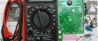
Using a multimeter
If you want to check triacs for penetration using a tester, you need to change the device system to acoustic mode.
The standard location of the transceiver can be seen in the image below. A1 and A2 are electrical power terminals, thanks to which current passes to the load, and G is the main electrode.
Since the transceiver tends to vary, it is necessary to study it in the description of the triac.
In order to check a part for penetration, it is necessary to touch terminals A1 and A2 with probes; if the part is working properly, “1” or 0L will be indicated on the screen; if there is a penetration, a value close to 0.
In cases where there is no short circuit between terminals A1 and A2, it is necessary to examine the main electrode.
First, you need to touch some power terminal and the main electrode with the probes; the values should be low 80-200.
If you want to check whether a triac can open, you need to short-circuit its main electrode with one of the multimeter leads, thus applying current to it.
You can see instructions for checking using the example of a thyristor and triac below.
After removing the voltage from the main electrode, the triacs can be closed. Due to the fact that at least the smallest current must flow in order to maintain conducting conditions.
Similar properties may exist in methods that we will consider further.
Description of the scheme
The electrical circuit diagram of the device is shown in Fig. 1. Supply transformer TR1 reduces the 220 V mains voltage and provides galvanic isolation between the mains and the probe circuits. The secondary winding TR1 is made with a middle point, from where the voltage is removed with an effective value of approximately 2 × 9 V. The full-wave rectifier is assembled on the diode bridge D1. Smoothing of positive and negative voltages is provided by capacitors C1 - C4. The voltage at the AP contact relative to the common wire (A1) is approximately +11 V, while the voltage at the AN contact is approximately -11 V. Switch SW3 changes the polarity of the lamp supply voltage.
A stabilized supply voltage of ±5 V is generated using positive voltage regulators (7805) and negative voltage regulators (7905) and provides normalized control current.
Diodes D2 and D3 prevent a sharp drop in the input voltage of the stabilizers when the thyristor or triac under test is unlocked.
The magnitude of the control current is determined by resistors R1 - R8, connected to the control electrode circuit using switch SW2. The voltage at the control electrode of a thyristor or triac is approximately 1 V, so the value of the control current is calculated using the following formula: Iу=4/R
Resistance R corresponds to the resistance in the control electrode circuit of the thyristor or triac. The probe will allow you to determine the maximum value of this resistance for various starting methods with a control voltage of 5 V.
Various methods of unlocking the triac are implemented through four possible combinations of switch positions SW3 and SW4.
For the thyristor, the only mode + + is used (see table), which corresponds to the position AP of switch SW3 and the position GP of switch SW4.
Rice. 1. Electrical circuit of the probe (1 of 2).
Rice. 1. Electrical circuit of the probe (2 of 2}.
Using a battery with a light bulb
In this way, you can check triacs in cases where you don’t have a multimeter, just using a light bulb. You can see the verification model for this method below.
In cases of testing a triac with a battery and a light bulb, it is necessary to remove resistor R1 from the chain. To do this, you need to use 3 alternately connected AA batteries or a crown.
In cases of assembling a portable tester according to this scheme, you have the opportunity to mount a button without focusing with the contacts shown on the model.
Provided that you are not going to make this device, you need to briefly touch the main electrode with the wire, as you already saw in the multimeter method.
Circuit for testing thyristors
Every radio amateur should have his own small laboratory. But what to do if you don’t have enough money even for a simple soldering station? This article will talk about how to make a simple device for testing thyristors from available radio elements, which will be added to your collection of useful devices for a radio amateur. Now you will know for sure whether your thyristor is broken or is still alive.
Circuit for testing thyristors
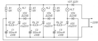
The thyristor belongs to the diode class. You can check it with a multimeter, but if your hands grow from the right place, then of course it’s easier to assemble a device for testing. And here is the diagram:
The scheme consists of:
– a transformer that gives us 5-10 Volts at the output
- diode D226, whatever was at hand. You can use any low-power one.
– electrolytic capacitor 1000 uF x 25 Volts
– toggle switch (S1) for three positions, one of which is neutral (N)
– return button (S2)
– 47 Ohm resistor
– 6.3 Volt incandescent light bulb
Assembly and description
So, let's start with the fact that we need foil PCB. I got some textolite from my stash that was not the first freshness. In order not to worry about wiring elements, etching the board and other various hemorrhoids, for simple circuits I stupidly cut squares and make a simple homemade board. Believe me, this is much faster if you don’t have ready-made Chinese breadboards at hand. To do this, I take an iron file, an iron ruler and scratch out shallow grooves:
If only there was no copper between the squares. Some people manage to make special sharpening points from an iron file, but I don’t like them because they quickly become dull and have to be sharpened.
Next, the whole thing needs to be sanded with fine sandpaper:
The next step is to select a transformer. We select the transformer in such a way that it produces an alternating voltage of any value from 5 to 10 Volts. My transformer produces 12 volts at the output of the secondary winding. I had to unwind half the turns from the secondary winding. Now it produces 6 Volts. For those who don’t know how a transformer works, you can read this article. We make holes for the transformer, mount it on the edge of our homemade printed circuit board and draw out its terminals from the secondary winding onto squares. In order to tin a square, we just need to rosin it a little and add a drop of solder:
This is roughly what the transformer looks like on the board:
And here is the completed structure assembled. All that remains is to find a suitable housing for it.
How to test thyristors
The scheme works as follows:
1)We connect the thyristor T1 being tested to the wires of the circuit.
2)Switch the toggle switch S1 with the neutral position to the “ icon
”, press button S2.
3)The light comes on when pressed and goes out when released.
Thus, we tested the thyristor on alternating current.
4)Next, set the toggle switch S1 to the “=” position
5)We press the S2 button, the light comes on, we release the S2 button, the light still continues to light.
So we tested the thyristor at direct current.
If all operations were successful, then our thyristor is in perfect health.
And here is the video for those who are too lazy to read the above text. Here I checked the KU202N thyristor.