Every experienced electrical engineer knows that the distribution of current density in a conductor is nonlinear. The closer to the central axis, the smaller the signal amplitude. At high frequencies, for a correct calculation it is enough to take into account the passage of waves through a certain surface layer. This phenomenon, the skin effect, can perform useful functions. For successful application in practice, in addition to the general theory, you need to study the calculation methodology.
Economical pipeline heating systems are created based on the skin effect.
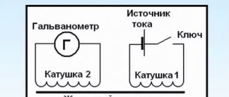
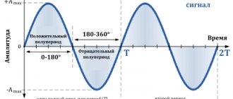
Explanation of the surface effect
It should be emphasized that the current density is the same when connecting the conductor to a constant voltage power source. However, the situation changes when a wave signal passes through.
Current density distribution in a conductor
Physical picture of occurrence
To explain the reasons for the phenomenon, you can use the second part of the explanatory picture above. The force effects that are generated by an alternating field are shown in graphical form. The electrical component (E) is directed opposite to the current (I), which explains the resulting resistance and the corresponding decrease in amplitude. As you approach the surface, the opposite effect will appear. It is caused by the coincidence of tension vectors.
Equation describing the skin effect
To express the amplitude in terms of current density, constitutive relations are taken from the classical equations of Ohm's law and Maxwell's formulas. Using the differential over a given time interval, you can calculate the values of the magnetic and electric components of the field. In a simplified form, we consider an infinite conducting sample created from a homogeneous material.
Properties of fast alternating currents
Definition 1
High-frequency currents are considered to be currents that have a frequency higher than $10,000 Hz$. For these currents the quasi-stationary conditions are not satisfied. As such a current flows through a conductor, eddy currents appear in the conductor, which are generated by changes in the magnetic field at high speed.
Changes in the magnetic field in a conductor occur in such a way that on its axis the eddy current has a direction opposite to the main current, and at the surface of the conductor the flow of this current coincides with the direction of the main current. This means that the high-frequency current has a variable density across the cross section. The current density at the center of the conductor cross-section is almost zero. It increases when moving towards the outer surface. At very high frequencies, current flows through the thin outer layer of the conductor.
Are you an expert in this subject area? We invite you to become the author of the Directory Working Conditions
Nowadays high frequency currents are widely used. High-frequency melting furnaces are used to quickly heat up metal bodies. Using high-frequency currents, steel parts are hardened. The object is briefly placed inside a coil of high frequency current. The surface layer of the part is heated by eddy currents, while its interior remains cold. The part is removed from the coil, the inner part quickly takes away heat from the surface layer, the surface quickly cools and hardens. The heating depth is controlled by the holding time of the part in the coil and the frequency of the current. After this procedure, the surface of the part becomes hard and durable, while the metal inside retains elasticity and ductility.
Formula for determining the cutoff frequency of the conductor diameter
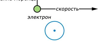
Hall effect
For practical calculations, individual minor factors are neglected. For example, to determine the cutoff frequency (Fcp), the circuit of a radio device is calculated based on the diameter (D) of the corresponding conductor. The most important characteristic of a certain material is added to the formula - resistivity (Rу) or conductivity (Sу). The dependence of the marked parameters shows the following expression:
Fav = 4/ (π*μ*Sу*D2),
where μ is a constant value (μ = 4* Su*10-7 Henry per meter).
Skin layer thickness
Capacitor in AC circuit
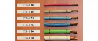
From the definition discussed in the previous section, the inverse dependence of the current density on the signal frequency is clear. The following table clearly demonstrates the “active” layer of a copper conductor. When the energy flow decreases multiple times in depth at a certain level, the use of thick power lines is inappropriate.
| Parameter | Values | ||||
| Signal frequency, Hz | 50 | 60 | 10 000 | 100 000 | 1 000 000 |
| Skin layer thickness, mm | 9,34 | 8,53 | 0,66 | 0,21 | 0,067 |
The first two columns show values for standard AC power. This data demonstrates that a relatively small change in frequency (10 Hz) renders 1.62 mm diameter conductor (copper) useless. It is not difficult to calculate significant savings when creating a long line after appropriate optimization of signal parameters. It should be remembered that each metal differs in the depth of the effective layer. Which option to choose will become clear after a thorough study of the intended purpose of the design.
Anomalous skin effect
A careful study of the phenomenon allows us to draw several important conclusions. As shown in specific examples, the skin layer has a shallow depth. However, the corresponding distance is much less than the average free path of charged particles. It should not be forgotten that a certain amount of energy must be spent on the corresponding movement. Overcoming the electrical resistance of the material is accompanied by heating.
If you lower the temperature, the conductivity will increase. At the same time, the free path will increase, and the thickness of the considered part of the conductor will decrease. At a certain level, the standard mechanism of wave interactions will become insignificant. The anomalous skin effect is a change in the size of the layer in which the current density is sufficiently high for practical use.
Charge carriers and their movement
In the absence of an electric field, free point charges are in equilibrium. They carry out vibrations, interacting with each other and with ions of the same or opposite sign. However, the picture of equilibrium is instantly disrupted when the metal enters an electric field. An electrical displacement occurs on a charged conductor.
Under the influence of Coulomb forces, a redistribution of electrons occurs in the metal body. The movement of charges is facilitated by the field strength acting on carriers of charged particles of different signs, but in different directions.
As a result of this impact, charged particles rush in opposite directions. More precisely, in metals only the movement of electrons occurs, which accumulate on the surface on one side.
Positive ions bound by the atomic forces of the crystal lattice do not move, but since the electrons rushed in one direction, holes (positively charged ions) predominate on the other side of the conductor (see Fig. 1). Thus, it can be argued that electrons and positive ions under the influence of an electric field are distributed in opposite directions on the surface of bodies. That is, charges tend to equilibrium distribution.
Rice. 1. Distribution of charges in a conductor
The process of particle distribution continues until their interaction between external and internal forces is balanced. That is, until the sum of the external electric field strengths equals the internal tension. This process lasts a fraction of a second. If the energy density does not change and the metal remains calm, then the balance of forces is a constant.
Taking into account the directions of external tension vectors and internal forces acting on the conductor, we can write:
Resulting tension vector
A zero value of field strength means that the internal potential of the body is compensated by the action of external forces:
If you place a metal ball in an electric field, then all the static electricity on its surface will have the same potential. Such surfaces are called equipotential surfaces. Charges accumulated under the influence of field strength forces are called induced or excess. The presence of excess charges is typical for all types of conductors caught in an electric field.
The reasoning given above is also valid for substances with free ions of different signs (solutions of salts and acids). As a result of this distribution, the charges are also located at opposite ends of the conductive body. In this case, the equality written above remains unchanged.
Rice. 2. Conclusions
Another important property of conductors: when additional charges are given to them, their own charged particles are distributed so that equilibrium is restored. For example, when adding negative charges, the latter will counteract the excess electrons, trying to take their place on the surface of the body.
If the conductor is insulated, then up to a certain time the amount of induced electricity will increase until a new equilibrium is restored. In this case, the internal field strength, increased by charge densities, will increase its resistance. Eventually, there will come a point when repulsive forces stop the flow of the same static electricity.
If you create conditions for the removal of excess charged particles (while maintaining the influx of new ones), for example, by grounding the conductor, then an electric current will arise. Moreover, the movement of charged particles will take place along the surface of the metal, but not inside it, as one might expect.
Application
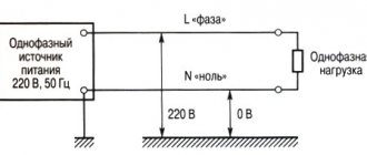
The surface effect allows for local heating of part of the conductor when alternating current is passed through. This principle is used to heat the pipeline in winter. Correct application of technology implies the following advantages:
- lack of accompanying control and functional devices;
- virtually unlimited route length;
- possibility of safe use of high temperatures.
Frequency distribution of current density is used to transmit information signals along power lines. If the wavelength is sufficiently reduced, the proximity of the central part of the conductor will not be an obstacle. The modulated microwave component passes through the surface layer. To create data packets and decrypt, special encoding (decoding) devices are used.
For your information. Similar mechanisms are used in the oil industry to assess well productivity. The skin factor determines the resistance to fluid movement in the formation area close to the technological hole. This parameter is used to estimate the actual production volume compared to ideal conditions.
Depth of current penetration into metal
November 6, 2018
Surface effect phenomenon
Direct current in the conductor is distributed evenly over the cross-section, alternating current is distributed unevenly over the cross-section depending on the frequency of the current (Fig. 10.6.).
Rice. 10.6. The depth of current penetration into the metal depending on its frequency: a - constant, b, c, d - alternating 50, 10,000, 125,000 Hz, respectively
When an alternating current is passed, the greatest back-electromotive force is induced at the center of the conductor, which is covered by the full magnetic flux. The closer to the surface of the conductor, the weaker the magnetic field, and, consequently, the less the counter-electromotive force. The existence of this force is equivalent to the appearance in the conductor of some additional resistance, called the inductive reactance of the circuit. Meeting the greatest inductive resistance in the center of the conductor, the current will tend to pass in the direction of least resistance and be squeezed out to the surface of the conductor.
The property of high-frequency current to flow only through the surface layer of a conductor is usually called the surface effect,
or
skin effect.
The current density for different points of the conductor cross-section will be different. The higher the frequency of the current, the greater the inductive reactance at the center of the conductor and the lower the current density. The uneven distribution of induction currents leads to uneven heating of parts: the surface layers very quickly heat up to high temperatures, and the core either does not heat up at all or heats up slightly, due to the thermal conductivity of the steel.
To quantify the surface effect phenomenon, the concept of current penetration depth
8 (delta). In this case, it is believed that alternating current flows only in the surface layer, the thickness of which is equal to the depth of current penetration, and has a uniform density at this depth.
The current penetration depth or layer thickness is determined by the formula:
where p is the electrical resistivity, Ohm-mm2/m; p—magnetic permeability, G/E; f - current frequency, Hz.
Consequently, with increasing frequency, the penetration depth of induction currents decreases (Fig. 103, table 10.4.). If you change the frequency of the current, you can change the penetration depth 8 within a wide range, and, consequently, the thickness of the layer through which the current flows, causing heating of the surface of the hardened part.
From the data presented in the table, it follows that with increasing heating temperature of the metal, the depth of current penetration increases and reaches its greatest value at the temperature of loss of magnetic properties - the Curie point.
Table 10.4
Depth of current penetration into metal at various frequencies
| Current frequency, Hz | Current penetration depth, cm | ||
| Steel 45 | Electrolytic copper | ||
| at t=15°C, P =2-10 -50m-cm, ^ =40 G/E | at t = 800°С, Р =10 - 4 Ohm-cm, ^=1 G/E | at t =15°С, P = 1.8.10 -6 Ohm-cm, ^ =1 G/E | |
| 50 | 0,5 | 7.0 | 1,0 |
| 2500 | 0,067 | 1.0 | 0,13 |
| 10000 | 0.034 | 0,5 | 0,07 |
| 100000 | 0,011 | 0.16 | 0,022 |
| 1 000 000 | 0,0034 | 0,05 | 0,007 |
With increasing heating temperature (Fig. 10.7.) of steel parts, the resistivity p increases and above 1000°C reaches its maximum value.
Rice. 10.7. Curves of changes in magnetic permeability and electrical resistivity of steel 45 depending on heating temperature
Magnetic permeability in the range 600...700°C is almost independent of temperature, but with further increase it drops sharply and reaches a minimum value equal to the magnetic permeability of vacuum ( jli = 1).
For practical calculations, the depth of penetration of current into metal is calculated using simplified formulas: for steel parts at a temperature of 15 ° C:
mm and at a temperature of 760° C, mm
Where: S - current penetration depth, mm; f - current frequency, Hz.
For most steels, magnetic transformations occur in the critical temperature range of 765-780 ° C, at which the magnetic permeability drops sharply and becomes equal to unity. After the steel loses its magnetic properties with the formation of austenite, the depth of current penetration increases sharply.
The largest value of current penetration depth is called hot penetration depth
and denote GOR. It can be approximately determined using a simplified formula:
Knowing the dependence of the depth of current penetration on temperature, the process of induction heating of steel can be represented according to the following diagram.
At the first moment, heating of the steel begins in a thin surface layer equal to the depth of penetration of the current into the cold metal. After this layer loses its magnetic properties, the depth of current penetration increases and the layer located deeper is heated. The temperature increase in the first heated layer slows down.
After the second layer loses its magnetic properties, the third layer begins to heat up quickly, and so on. The limit to the growth of current penetration depth is the hot penetration depth.
The temperature increase in the layer with hot penetration depth occurs due to induced currents, and in deeper layers - mainly due to thermal conductivity.
This heating process explains the reason for the rapid spread of heat when heating HDTV, due to changes in magnetic properties. In Fig. Figure 10.5 shows a graph of induction heating, from which it can be seen that faster heating occurs at temperatures below the Curie point (769 ° C). Above this critical point, heating slows down due to the loss of magnetic properties of the steel and phase transformations.
There are three main methods of surface induction hardening depending on the size, shape of the part and some special heating requirements: simultaneous, continuously sequential and sequential (alternate).
Rice. 10.8. Induction heating schedule
Taking into account the effect in technology and combating it
This phenomenon has a noticeable effect as the signal frequency increases. The skin effect should be taken into account when designing circuits with alternating (pulse) currents. In particular, they make corrections to the calculation of the filter coil, oscillating circuit, and transformer.
Typical ways to solve the identified problems:
- reducing the thickness of the conductor;
- creation of hollow structures;
- formation of a surface layer of metal with better conductivity;
- elimination of irregularities;
- weaving of several isolated strands.
For your information. Radical elimination of harmful phenomena is organized using direct current electricity transmission.
Charge distribution and body shape
As noted above, the distribution of charges depends on the shape of the body. Most static electricity collects on protrusions, especially on sharp ends (see Fig. 3, 4).
Rice. 3. Body shape and static electricity distribution
Rice. 4. Distribution of static electricity on the conductor
As can be seen from Figure 4, the charge distribution density on concave surfaces is minimal. The electrostatic field of solid and hollow conductors is no different if their surfaces are identical. In other words, all conductive bodies with the same surfaces have the same surface densities.
On spherical surfaces, static electricity is distributed evenly. The capacitance of a capacitor (spherical) is calculated using the formula:
Capacitance of a spherical capacitor
where R1 and R2 are the outer and inner radii of the spherical capacitor.
The distribution of static electricity on a sphere is illustrated in Figure 5. Please note that inside a spherical body, as well as any other, there are no charges: vector E=0, φ=const.
Rice. 5. Distribution of charged particles on a sphere
You've probably heard of the Faraday cage. A person who is in a confined space made of conductive material, that is, in a cage, does not feel the influence of powerful discharges. Static electricity flows down the surfaces of the cell walls to the ground and cannot enter the cell.
Ways to suppress the skin effect
The listed techniques are of particular importance when working with high-frequency radio signals. In particular, to improve conductivity, the surface layer is created from silver, platinum, and other noble metals. The following recommendations are used in practice when creating high-quality audio equipment:
- thin (0.25-0.35 mm) wires are used to transmit signals;
- by braiding the cable, significant distortions of the magnetic field lines are eliminated;
- reliable insulation prevents copper oxidation;
- check for the presence of other lines nearby that can have harmful mutual influence.
Fiber optic communication line
When moving to the microwave range, signals are transmitted through waveguides. Eliminate possible negative manifestations by transmitting data via signals in the optical range.