The phrase about “ burning out zero”
“Every one of us has probably heard. Why does the mysterious zero tend to burn out all the time? In order to bring some clarity to this issue, it is necessary to recall something from a high school physics course.
For a single-phase circuit, "neutral" is simply the name for the conductor that is not at high potential with respect to ground. The second conductor in a single-phase circuit is called a “phase” and has a high alternating voltage potential relative to ground (in our country, most often only 220 V). The single-phase zero does not show any tendency to burn out.
The trouble is that all electrical communications (i.e. power lines) are three-phase. Let's consider a “star” circuit, in which the concept of “neutral wire” appears.
The alternating currents of each phase in three identical loads are phase shifted by exactly one third and ideally cancel each other out, so the load in such a circuit is usually called a three-phase concentrated load. With such a load, the vector sum of the currents at the midpoint is zero. Neutral wire
, connected to the middle point, is practically not needed, since no current flows through it. Minor current only appears when the loads on each phase are not completely equal and do not completely cancel each other out. Indeed, in practice, many types of three-phase four-core cables have a neutral core of half the cross-section. There is no point in wasting scarce copper on a conductor through which practically no current flows. The three-phase zero also does not show any tendency to burn out under a three-phase concentrated load.
Miracles begin when single-phase loads are connected to three-phase circuits. At first glance, this is the same case, but there is one small difference. Each single-phase load is a completely randomly selected device, i.e. single-phase loads are not the same. It is foolish to think that different single-phase consumers will always draw the same current. Single-phase loads
in three-phase circuits they always try to bring it as close as possible to
three-phase loads
. This means that when connecting single-phase consumers to a three-phase network, they try to distribute their power across different phases so that each phase carries approximately the same load. But complete equality is never achieved and it is clear why. Consumers randomly turn their electrical equipment on and off, thereby constantly changing the load on their phase.
As a result, complete compensation of phase currents almost never occurs at the midpoint, but the current in the neutral wire usually does not reach its maximum value equal to the highest current in one of the phases. That is, the situation is unpleasant, but predictable. All wiring is designed for it, and zero burnout
usually does not happen, and if it does, it is extremely rare.
This situation developed in the 90s of the 20th century. What has changed by this time? Switching power supplies have come into widespread use. This power source is used for almost all modern household equipment (TVs, computers, radios, etc.). The entire current of such a source flows during only one third of the half-cycle, i.e., the nature of current consumption is very different from the nature of current consumption by classical loads. As a result, additional pulse currents arise in the three-phase network, which are not compensated at the midpoint. Do not forget to add to this the uncompensated currents caused by the presence of single-phase loads in a three-phase network. In such a situation, a current often flows through the neutral wire, close to or exceeding the largest current of one of the phases. These are the conditions favorable for “zero burning out.” The conductors in three-phase cables have the same cross-section, calculated according to the maximum load power, therefore, the neutral conductor has the same cross-section as any of the phase conductors, and today more current can flow through it than through any phase conductor. It turns out that the neutral conductor operates under overload conditions, and the likelihood of it burning out increases.
What is a zero break?
To fully answer this question, it is necessary to provide examples of the normal operation of a three-phase power supply input circuit. As an example, we will give a simplified version with an input for a floor distribution board.
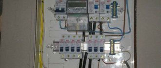
Scheme 1. Normal operation of the system
As can be seen from the figure, each of the apartments on the floor is powered from a separate phase (L1 - L3) and a common zero. Which forms a phase voltage of 220 volts (L1N=L2N=L3=220 V) in the household network of each apartment. In this case, a TN-CS power supply circuit is used, where a PE grounding bus is used, connected to the neutral in the building switchgear. The above system is balanced, since the load current in the phase wires is summed through the zero line, which reduces the likelihood of phase voltage imbalance.
Note that it is quite difficult to completely eliminate this phenomenon, since the load resistance at each phase may vary. For example, in apartment_1 the air conditioner and washing machine are turned on, in apartment_2 the owner turned on the boiler and electric stove, and in apartment_3 there are no residents and all household appliances are unplugged. As a result, voltage asymmetry will occur in a three-phase power system.
Now let's look at the network operation in abnormal mode, when the zero burns out.
Phase imbalance in a three-phase network: what is it, causes, consequences, protection
The most common problem that gives rise to a lot of destructive consequences is phase imbalance in a three-phase network (up to 1.0 kV) with a solidly grounded neutral. Under certain conditions, this phenomenon can damage electrical appliances and pose a threat to life. Considering the relevance of the problem, it will be useful to know what current and voltage asymmetry is, as well as the reasons for its occurrence. This will allow you to choose the most optimal protection strategy.
What is phase imbalance?
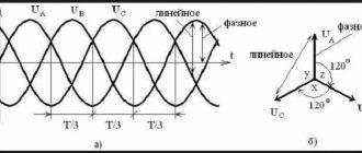
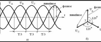
This term is used to describe a network condition in which uneven loads occur between phases, which leads to imbalance. If you make a vector diagram of an ideal three-phase network, it will look like the one shown in the figure below.
Voltage diagram in ideal three-phase networks
As can be seen from the figure, in this case both linear voltages (AB=BC=CA=380.0 V) and phase voltages (AN=BN=CN=220.0 V) are equal. Unfortunately, in practice it is impossible to achieve such ideal equality. That is, the linear voltages of the network, as a rule, coincide, while in the phase voltages there are discrepancies. In some cases, they may exceed the permissible limit, which will lead to an emergency.
Example of a stress diagram when a misalignment occurs
Acceptable norms of skew values
Since it is impossible to prevent and completely eliminate imbalances in three-phase networks, there are asymmetry standards that establish permissible deviations. First of all, this is GOST 13109 97; below is an excerpt from it (clause 5.5) to avoid discrepancies in the document.
Voltage asymmetry standards GOST 13109-97
Since the main reason for phase imbalance is directly related to improper distribution of loads, there are standards for their ratio prescribed in SP 31 110. We will also provide an excerpt from this set of rules in the original.
Cutting from SP 31-110 (clause 9.5)
Some clarification of terminology is needed here. To describe asymmetry, three components are used: direct, zero and reverse sequence. The first is considered the main one; it determines the rated voltage. The last two can be considered as interference that leads to the formation of corresponding EMFs in the load circuits, which do not participate in useful work.
Reasons for phase imbalance in a three-phase network
As mentioned above, this condition of the electrical network is most often caused by uneven connection of the load to the phases and a zero break. Most often this manifests itself in networks up to 1 kV, which is due to the peculiarities of the distribution of electricity between single-phase power receivers.
What happens in the electrical network when the zero is broken?
Let us consider separately the change in the operating mode of a three-phase network in the event of a break in the main neutral and how single-phase electrical wiring will behave if the neutral conductor burns out at the input.
Zero burnout in a three-phase network
Let's make changes to Figure 1 caused by an accident, namely the disconnection of zero.
The neutral main conductor is broken
In this case, a break in the common neutral wire will cause the flow of electric current through it to stop. As a result, all apartments R1-R3 will be powered using the “star” connection type without a neutral line. In other words, if the zero is broken, each apartment will receive not phase, but linear voltage.
Contour of apartments 1 and 2
As an example, we suggest considering how the situation will develop in apartments 1 and 2. The load of electrical appliances is summed up in this circuit when current I12 passes through it. Accordingly, the voltage level for apartments will be set depending on the load of devices connected to the network. That is: U1 = I12*R1, and U2 = I12*R2. It follows from this that the total current will be I12 = U12 / (R1+R2):
Please note that the total voltage of the circuit will be equal to the linear voltage in this electrical network, that is, U12 = 380 volts. But at the same time, the indicators U1 and U2 can vary in the range of 0-380 volts and, naturally, differ significantly from each other. These values can be influenced by both the load of connected devices in each apartment, as well as its active and passive components.
As a result, if problems occur with the transformer neutral (source zero), there is a high probability of failure of devices connected to the network. The reason is an increase in the voltage level in the network.
Zero break in a single-phase network
In this situation, the consequences will not be as sad as in the case described above, but, nevertheless, if the input zero in the TN-C system burns out, this can pose a serious danger to human life.
Zero burnout in a single-phase consumer circuit
For single-phase loads, a zero break will be similar to a power outage, except for the fact that a potential will remain on the phase wire, which poses a danger to life. Moreover, it will also appear where there was previously a protective zero in the contacts of the sockets. If the housings of electrical appliances were grounded with a working zero, then the likelihood of negative consequences is very high. In TN-CS systems, the risk factor is significantly reduced through the use of a PEN conductor.
Three-phase network: why zero burnout occurs
For the most part, household consumers are powered using a single-phase circuit. But part of the power supply is still carried out using three-phase cables. Of course, high-quality cable products are characterized by strict technical and conductive parameters, which means they need to be laid and operated according to the rules, taking into account permissible load parameters.
What does the electrician’s phrase “Zero burnt out!” mean? Why does zero burn out much more often in a three-phase network than in a single-phase one? What are the forecasts? These and other questions arise for owners of houses and other objects with similar power supply. Let's figure out together how to prevent the development of such situations, thereby reducing the consequences and problems.
The concept of “zero” in a single-phase circuit
“Zero” for a single-phase circuit is one of two conductors that does not have a high potential relative to ground. The second conductor is the “phase”, which has a high potential (220 V for household networks). The electric current that flows through the phase is always equal to the current that flows through “zero”. That is why there are no prerequisites for zero burnout in a single-phase network. In addition, the line, as a rule, is protected by high-quality and inexpensive automation.
This is what it looks like schematically:
The concept of “zero” in a three-phase circuit
As many people know, three-phase lines are of two types regarding the load to the phases. Thus, the following types are distinguished: “star” and “triangle”. In the case of a delta connection, the zero is absent purely physically, which means there is simply no problem with the zero burning out. But the “star” circuit in a three-phase connection has a zero, like a special conductor. Let's take a closer look.
How to protect yourself?
Having learned about the danger posed by the loss of zero, we suggest considering options for protecting against this phenomenon:
- You need to start with proper installation of electrical wiring. If it is planned to use a three-phase power supply circuit to power the facility, then it must be calculated in such a way as to minimize the likelihood of phase imbalance. That is, it is necessary to systematically distribute the load on each line.
- Devices that balance the load on each phase should be used in network management. Moreover, ideally, this work should be carried out without the involvement of operators, that is, it should be performed automatically when the zero is broken.
- It should be possible to quickly change the consumer connection scheme. This allows adjustments to be made if at the design stage the load on each section was not properly taken into account or the power consumption increased due to the commissioning of new facilities. That is, if a critical situation arises, it must be possible to change the power. An example is when an apartment building is transferred to a line with a higher load to “dilute” the phase imbalance that occurs when the zero is broken.
In the above options, we considered protection against distortions on a global scale; the end user can provide the required level of protection much easier. To do this, it is enough to install a voltage control relay, in which you indicate the permissible minimum and maximum levels. As a rule, this is ±10% of normal.
Let's sum it up
Of course, the probabilities of accidents are random; the most that can be done in such situations is to take the necessary measures to ensure protection. But besides this, it would not be superfluous to identify an emergency situation in time based on its characteristic signs. First of all, the burning out of the neutral main wire leads to network overvoltage. Having discovered the first signs of this phenomenon, you should turn off all electrical appliances.
Doing this quickly and independently is almost impossible. The time period for this is too short, so you should install special devices on the electrical panel that respond to a zero break. As soon as the voltage goes beyond the set limits, the voltage control relay will perform a protective shutdown.
You should not completely trust the security system. It may happen that if there are characteristic signs of voltage surges, a power outage will not occur. Therefore, it makes sense to list the most likely manifestations for this phenomenon:
- Flickering of incandescent lamps . They are most sensitive to the difference in voltage level that occurs when the zero is broken. Energy-efficient lighting fixtures and LED lamps are not as responsive to changes.
- Electronic devices with built-in protection are usually disconnected from the power supply. Or they don't start. Such actions are provided for by the protection response of pulsed power supply units to voltage surges. It is typical that such a reaction can operate earlier than the voltage relay. But this largely depends on the manufacturer and the implementation scheme for protecting electrical networks, as well as the reliability of the electrical connection.
- Another characteristic sign is an increase in the temperature of the switch . Even if you did not pay attention to the flickering of the lamps, this manifestation should cause concern.
- Sparking when trying to connect an electrical appliance may indicate a zero break at the input of a single-phase consumer. Even if it is caused by another factor, and not a zero break, this is a very bad sign.
- Spontaneous operation of input circuit breakers may also indicate overvoltage. This reaction to a zero break is typical when turning on electric heating devices, such as an electric furnace, boiler, kettle, etc.
- Characteristic sounds in the input electrical panel may also indicate voltage drops. In such a situation, it is recommended to turn off the power input and wait for the emergency team to arrive. There is a high probability that a zero-loss accident occurred in the supplier’s power grid.
- a voltage relay at the electrical network input . Ideally, it is advisable to duplicate this system with a voltage stabilizer for a house or apartment. Such a device, working in tandem with a relay, will allow you to maintain a given voltage level without turning off the power.
In fact, only multi-level protection can provide maximum security.