Ferroresonance phenomena in electrical networks
The main factors that give rise to ferroresonance phenomena in electrical networks are elements of capacitive and inductive types.
They are capable of forming oscillatory circuits during switching periods. This effect is especially noticeable in power type transformers, linear booster transformers, shunt circuits and similar devices that are equipped with massive windings. This phenomenon comes in two types: resonance of currents and voltage.
Voltage ferroresonance is possible when there is inductance in the network, characterized by a nonlinear current-voltage property. This characteristic is characteristic of inductors, where the cores are made from ferromagnetic components. This is especially true for rectifiers from the NKF line. This negative phenomenon is caused by a small indicator of resistance of ohmic and inductive types in relation to power transformers.
What is ferroresonance
Ferroresonance is a phenomenon of a sharp increase in current, leading to overheating and damage to the converter and related electrical equipment.
The resonance that causes an accident is observed when an oscillatory circuit occurs with a series connection of the VT inductance and the network capacitance.
Why does it appear in transformers?
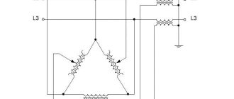
The phenomenon of resonance occurs when the neutral is ungrounded (isolated) together with an open-phase mode. With an isolated neutral, the network capacitance relative to the ground forms a series connection with the inductance of the ungrounded VT structure. An open-phase mode occurs when phases are partially switched on, during a phase break, or during an asymmetrical short circuit.
Ferroresonance in a voltage transformer
When a voltage transformer is connected to the network, series-combined LC circuits are formed in it, which are a resonant-type circuit. When an inductive element with a nonlinear current-voltage property is connected in series to a capacitive-type element, the voltage in this zone of the circuit is characterized as active-inductive.
After a certain time period, the voltage value on the inductive element becomes peak, the magnetic circuit is energized, and the voltage on the capacitive type component continues to increase. Ferroresonance in a voltage transformer occurs when the voltage of the inductance and capacitive element becomes equal.
The rapid transition of the applied voltage from the active-inductive type to the active-capacitive type is referred to as “phase reversal”. This effect is dangerous for electrical appliances.
Which transformers neutralize the effect of ferroresonance
To prevent sudden current overloads, protective voltage transformers are designed in conjunction with zero sequence transformers (ZPTs). Such specialized devices are called anti-resonance devices.
NAMIT-10-2
The equipment belongs to the TN type (N), A - anti-resonance (A), with natural oil cooling (M), for measuring circuits (I), three-phase (T), rated voltage 10 kV, version 2.
The measuring equipment consists of two units located in a common housing:
- TNKI is a three-winding TN for insulation control;
- TNP is a two-winding TNP that protects TNKI from accidents due to short circuits of individual phases. Photoresonance is compensated by the inductive reactance of the TNP in the primary circuit of the converter.
NAMI-10-95
Anti-resonance, oil, measuring equipment consists of:
- three-phase three-rod direct (negative) sequence VT with an additional secondary winding;
- single-phase two-rod TNP with a secondary winding connected in a closed delta circuit, which reduces the zero-sequence resistance of the device to the value of the leakage resistance.
NALI-SESH-6(10)
The NALI-SESH-6(10) equipment is represented by a cast (L) three-phase anti-resonance group of meters with a rated voltage of 6(10) kV.
The difference between the cast version and the oil version is its high fire and explosion safety, which makes it suitable for use in special conditions, for example at nuclear power plants.
NALI-SESH-6(10) is made using four active elements:
- a block of three single-phase, two-pole, measuring TN NOL-SESH, each of which contains up to three secondary windings;
- one TNP-SESH, which performs the function of protecting NOL-SESH from abrupt current transitions.
NALI-SESH-1
The equipment is made of single-phase TN with cast insulation type NOL-6(10) and TNP based on the operating principle and relay circuit of the NAMIT-10-2 device.
Ferroresonant stabilizers
Ferroresonance stabilizer
Ferroresonance rectifiers are not equipped with a built-in voltmeter, making it difficult to measure the output voltage of the network. You won't be able to adjust the voltage yourself. Ferroresonance type stabilizers partially distort real readings, the error is up to 12%.
Those who use such devices for a long time must remember that they are capable of emitting a magnetic field, which can disrupt the proper functioning of household electrical appliances. Stabilizers of this class are configured at the factory; they do not require any additional settings at home.
The influence of the stabilizer on technology
A ferroresonant voltage stabilizer, the operating principle of which is not simple, affects household appliances as follows:
- Radio receiver - signal reception sensitivity can be reduced, the output power indicator is significantly reduced.
- Music center - the output power of such equipment can be significantly reduced, erasing and recording new discs is significantly worse.
- TV – when connected to a stabilizer, you can observe a significant decrease in the quality of the picture on TV, some colors are not transmitted correctly.
The electrical circuit of modern ferroresonant type normalizers has been improved, which allows them to withstand heavy loads. Such devices can guarantee precise regulation of the mains voltage. The adjustment procedure is performed by a transformer.
Mathematical models of voltage transformers
When studying ferroresonance processes, mathematical models of TN play a key role. A voltage transformer of the NKF-500 type does not have structural steel in the magnetic core and can be modeled using a simple equivalent circuit shown in Fig. 1, a. The main characteristic of the VT in this case is its magnetization curve (Weber-amp characteristic). This characteristic was calculated based on the geometry of the magnetic core of the TN type NKF-500 and is shown in Fig. 1, b. In the diagram in Fig. 1, a: - VT flux linkage; i is the magnetizing current of the voltage transformer; R1 is the active resistance of the NKF-500 HV winding; R0 is an active resistance that models losses in the steel of the HP. In the mathematical model of the NAMI-500 type VT, it is necessary to take into account that in thick sheets of structural steel the electromagnetic field is displaced onto the surface of the sheets due to eddy currents (magnetic surface effect). The thickness of the structural steel plates is 6 mm. To take into account the surface effect, the sheet is divided into layers 0.5 mm thick (taking into account the symmetry of the sheet, there are only 6 layers). The magnetic flux in each layer is nonlinearly related to the field strength on the surface of the sheet.
Calculations of this dependence, as well as the dependence of active losses in each layer on the magnetic field strength, are carried out by numerically solving Maxwell’s equations using the finite element method in the FEMLAB package.
The dependence of the average induction in the sheet layers on the magnetic field strength on the sheet surface is shown in Fig. 2, a. When drawing up the magnetic equivalent circuit of the NAMI magnetic core, a sheet of structural steel, taking into account the division into layers, represents six parallel nonlinear magnetic resistances.
These resistances are 12 times less than the magnetic resistances of the layers, since there are six sheets of structural steel in the magnetic circuit in total and each is symmetrical relative to the middle (half a sheet is divided into layers).
The magnetic equivalent circuit of TN type NAMI-500 is shown in Fig. 2, b. The electrical equivalent circuit is shown in Fig. 2, c. In the diagram in Fig. 2, b: F1 - MMF of the HV VT winding; n1 — number of turns of the HV winding; 1 - total flux linkage in the magnetic circuit of the VT; ES - flux linkage in electrical steel; KS1KS6 - flux linkage in layers of structural steel sheet; RES, RKS1-RKS6 - magnetic resistance to flow, respectively, along electrical steel and across layers of structural steel sheet.
In the diagram in Fig. 2, in: nM - number of series-connected magnetic circuits in the NAMI500 cascade; RES0, RKS01-RKS06 - active resistances simulating losses in electrical steel and in layers of structural steel sheets; R1, L1 - active resistance and leakage inductance of the HV VT winding. From the dependencies in Fig. 2, but it can be seen that the magnetic field penetrates deep into the sheet of structural steel by only 1-1.5 mm.
Operating modes
The operating modes of stabilizers depend on a number of factors. The power indicator and the class of the device have a direct impact. The power characteristics of the device may be different; they must be selected taking into account the type of electrical equipment being connected.
The operating modes of the rectifier depend on the following types of load:
- inductive;
- active;
- capacitive
Active loading in its pure form is extremely rare. It is necessary only in those circuits where the variable value of the device has no restrictions. Capacitive loads can only be used for those rectifiers that have low power.
History of ferroresonance
https://electricalschool.info/spravochnik/electroteh/1789-chto-takoe-ferrorezonans.html
In 1907, the French engineer Joseph Bethenot published an article “On resonance in transformers” (Sur le Transformateur à Rеsonance), where he first drew attention to the phenomenon of ferroresonance.
The term “ferroresonance” was introduced 13 years later by the Frenchman Paul Bouchereau, also an engineer and teacher of electrical engineering, who in 1920 described this phenomenon in his article entitled “The existence of two modes of ferroresonance
" Bouchereau analyzed the phenomenon of ferroresonance, and showed that there are two stable resonant frequencies in a circuit consisting of a capacitor, a resistor and a nonlinear inductance.
It is now known that the phenomenon of ferroresonance is associated with the nonlinearity of the inductive element in the circuit of the circuit in the electrical circuit is called ferroresonance. For nonlinear resonance to occur, it is necessary that the circuit necessarily contain:
1) nonlinear inductance and linear capacitance;
2) either nonlinear capacitance and linear inductance.
This work is specifically devoted to the first version of the circuit consisting of nonlinear inductance
and linear capacity.
Operating principle of ferroresonance stabilizers
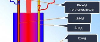
The primary winding, which receives the input voltage, is located on the magnetic core. It has a large cross-section, which allows the core to be kept in an unsaturated state. At the input voltage forms magnetic fluxes.
The output voltage is generated at the terminals of the secondary winding. A load is connected to this winding, which is located on the core, has a small cross-section and is in a saturated state. In case of anomalies in the mains voltage and magnetic flux, its value is not actually modified, and the EMF indicator also remains unchanged. During an increase in the magnetic flux, some of it will be closed on the magnetic shunt.
The magnetic flux takes on a sinusoidal shape and, as it approaches the amplitude indicator, a separate section of it goes into saturation mode. The increase in magnetic flux stops. The flow through the magnetic shunt will be closed only when the magnetic flux is equal to the amplitude.
The presence of a capacitor allows the ferroresonant stabilizer to operate with an increased power coefficient. The stabilization indicator depends on the level of slope of the horizontal curve with respect to the abscissa. The slope of this area is significant, so it is impossible to achieve a high level of stabilization without auxiliary equipment.
Radiant energy in a transformer
In addition to the ferroresonance phenomena described in the book, there are undoubtedly other phenomena not mentioned in it. Our task is to identify them.
At the beginning of my video “Addition No. 2 to the video: How a capacitor works in an alternating current circuit”
, available at the link
I have already given the text of the article “How to create your own creative laboratory.” So on page 5 of this test the following is written:
or her:
In the video, I will not be able to convey the subjective feeling in the hand from the twitching of a magnet located next to a configured operating transformer, but it is possible to show the presence of a radiant next to the transformer using an objective sensor. The sensor is a Sidorovich magnet, on behalf of the one who first made and used it.
Let's watch video fragment No. 3:
I am sure that physics professors will have to work hard to explain the phenomenon of rotation of this sensor, given that, according to theory, the entire magnetic flux should be inside the transformer core.
The transformer itself emits strong longitudinal waves, which can be detected by a scalar wave receiver.
Let's watch video fragment No. 4:
This concludes our preliminary acquaintance with ferroresonance. There are other interesting studies ahead, but before I finish filming this video, I want to touch on one more important point.
Advantages and disadvantages
Among the key advantages of ferroresonant rectifiers are:
- resistance to overloads;
- wide range of operational values;
- speed of adjustment;
- the current takes the form of a sine;
- high leveling accuracy.
But with all these advantages, devices of this class also have their disadvantages:
- The quality of operation depends on the load indicator.
- During operation, external electromagnetic interference is generated.
- Unstable operation at low loads.
- High weight and size indicators.
- Noise occurs during operation.
Most modern models do not have such disadvantages, but they are distinguished by their considerable cost, sometimes higher than the price of a UPS. Also, the devices are not equipped with a voltmeter, which makes it impossible to adjust them.
ESIS Electrical systems and networks
Ferroresonance in networks
with isolated neutral
Ph.D. tech. Sciences Polyakov V.S.
1.
Analysis of the causes of equipment damage in networks
with isolated neutral
A significant number of equipment damages in networks with an isolated neutral are caused by ferroresonance, since this phenomenon causes overvoltages or overcurrents for which the equipment is not designed and from which it is not protected. In addition, ferroresonance occurs more often than other types of influences, and is especially dangerous because the duration of its existence is unlimited.
Ferroresonance is a resonance in a circuit containing at least one ferromagnetic element.
Ferromagnetic elements in electrical networks are power transformers, arc suppression reactors, current and voltage measuring transformers, electric motors, that is, all devices that have a coil with a ferromagnetic (steel) core. A special feature of a coil with a ferromagnetic core is the nonlinear dependence of current on voltage (flux).
Under normal conditions, in such a circuit there are no conditions for the excitation of resonance, that is, undamped oscillations. However, when acting on a ferromagnetic element, leading to saturation of the core, a smooth change in the inductance of this element occurs, which creates the possibility of resonance between the inductance and capacitance.
Moreover, if in the network equivalent circuit the capacitance and inductance are connected in series with an alternating voltage source, then voltage resonance occurs, accompanied by a significant increase in voltage on the capacitance and on all network elements electrically connected to this capacitance. In this case, they talk about ferroresonant overvoltages.
If the capacitance and inductance of a ferromagnetic element are connected in parallel with an alternating voltage source, then a current resonance occurs, accompanied by a significant increase in the inductance and capacitance of the network. In this case, they talk about ferroresonant supercurrents.
as, for example, in open-phase modes. If capacitance and nonlinear inductance are mentioned in the failure reviews, damage to voltage transformers, electric motors, complete outdoor switchgears (KRUN), nonlinear surge arresters (OSL) and valve arresters. It is believed that these damages occur due to the occurrence of internal overvoltages.
Sufficient grounds for such qualification is the absence of compensating devices in the network, where their installation is necessary in accordance with the requirements of the Rules of Technical Operation (RTE) [1], in the presence of an arc fault or simply any single-phase short circuit to ground in the initial stage of damage development. Such a simplified approach does not allow us to identify the true causes of equipment damage and, therefore, to develop effective measures to prevent such cases. In some cases, damage is qualified due to the occurrence of internal overvoltages in conditions where their occurrence is generally impossible, for example, when events begin with a phase-to-phase short circuit (SC). True, the development of such damage is accompanied by the closure of large air gaps, not only in complete switchgears, where all insulating gaps are reduced, but also in closed switchgears of a conventional design with sufficiently large insulating distances, which creates the impression of exposure to high-multiplicity overvoltages. In fact, the closing of such large air gaps is caused by the effect of phase-to-phase short-circuit current on defective contact connections.
1.1. Development of damage in the presence of a defective
contact connection
The presence of a defective contact connection in a switchgear or switchgear can lead to the closure of large air gaps when this contact connection is exposed to phase-to-phase short circuit current. When exposed to short-circuit current in any contact connection, the contact pads melt. When calculating and designing detachable contact connections, this phenomenon is considered as positive, since melting of the contact pads leads to welding of the contact connection, and thereby to a decrease in its contact resistance.
| Rice. 1. Diagram of the development of damage to a defective contact connection under the influence of short-circuit currents, accompanied by melting of the contact pads and dynamic forces acting on the molten metal of the contact. |
However, a decrease in the total area of contact pads or contact pressure leads to an increase in the contact resistance of the contact connection, an increase in the amount of heat released during the flow of short-circuit current and the volume of molten metal. This molten metal, as well as the busbars through which the short-circuit current flows, is subject to powerful electrodynamic forces, which leads to the splashing of the molten metal into the interphase space and the closing of large air gaps in the area of the defective contact connection. Since the operating time of the relay protections that disconnect the supply transformer is quite long, amounting to one or more seconds, the occurrence of a phase-to-phase short circuit in the switchgear leads to a large amount of equipment damage, which makes it difficult to identify the root cause of the incident. It is possible to identify the original source of such damage by localizing the damage only in the area where the air gap is blocked due to metal splashing out of the contact connection. To do this, it is necessary to perform two measures: coating the switchgear insulation with a hydrophobic paste, which prevents the insulation from overlapping due to arc combustion products deposited on its surface, and accelerating the action of relay protection, for example, with a logical busbar protection device that turns off the input circuit breaker in the event of any overlap in the switchgear. It was in this way that it was possible to identify the cause of the annual overlaps in KRUN-10 kV substation No. 20 of Lenenergo in 1979. At this substation, copper lugs were soldered with tin-zinc solder to the aluminum cable cores. When exposed to short-circuit currents, this solder melted and splashed into the interphase space, which led to the blocking of air gaps about 60 cm long. After replacing all solder tips with crimped ones, the damage completely stopped. It should be noted that in all eight 10 kV sections of this substation, the single-phase ground fault current ranges from 150 to 200 A and that there is no compensation, however, eliminating the true cause of the overlap led to reliable operation of the equipment even in the absence of compensation for capacitive currents. Similar observations are available for other substations of Lenenergo and other power systems.
Indirect confirmation of the version about defective contacts as the root cause of damage can be a post-accident examination of contact connections of undamaged sections of the substation. Thus, at the South Lipetskenergo substation in 1991, damage occurred to several 6 kV switchgear cells when outgoing cables were damaged by a third party, accompanied by a phase-to-phase short circuit, which was qualified due to the occurrence of overvoltages. In the same year, when examining contact connections with a thermal imager at this substation, overheating of the plug-in contacts up to 160 °C was detected at currents less than the rated one. During a short circuit at such a connection, melting of the contacts with subsequent blocking of the air gaps is inevitable.
If, during the investigation of the damage, it is established that at the beginning of the events a two- or three-phase short circuit occurred on one of the network elements, then the occurrence of overvoltages as a cause of further development of the damage is unlikely, since the short circuit introduces the greatest possible attenuation into the zero-sequence circuit of the network in which it occurs development of resonant oscillations or accumulation of charges on the capacitance of network phases, which eliminates the development of overvoltages. It is more likely that damage will develop according to the scheme considered, and in this case it is necessary to take measures to improve the condition of the contact connections, rather than measures to protect against overvoltages.
1.2. Development of damage in non-full-phase modes
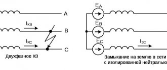
According to domestic and foreign studies, as well as operating experience, in networks with an isolated neutral, the occurrence of overvoltages is most often associated with open-phase modes. What is meant here is that the open-phase mode is not only an obvious break in the phase wire or a blown fuse, but also those cases when the disconnection of an unloaded step-down transformer or electric motor occurs by a switching device with non-simultaneous disconnection of all three phases. If the non-simultaneity of the shutdown is 0.04 s (2 periods of frequency 50 Hz) or more, then during this time overvoltages of dangerous magnitude have time to develop. In open-phase modes, ferroresonant overvoltages occur that exceed the insulation level of electric motors. They are dangerous for arresters with shunt resistances and arresters, as well as for voltage transformers due to their duration, since they last as long as the open-phase mode exists [2]. Their danger also lies in the fact that in open-phase modes the presence or absence of compensation does not affect the probability of occurrence and the level of overvoltages [3-5], while the installation of protective devices on the busbars is useless, since overvoltages occur in the phase section separated from the busbars ( after phase failure).
The open-phase mode leads to ferroresonant conversion of single-phase voltage to three-phase. The direction of phase rotation can be either forward or reverse. The establishment of direct phase rotation leads to a long-term increase in voltage to (2.2 - 2.3) × U f
and causes the VT fuses to blow.
In reverse alternation, the phase is reversed and one of the phase voltages increases to (3.8 - 4.2) ×U f
, and lightly loaded consumer motors begin to rotate in the opposite direction; in this case, damage occurs to the arresters with shunt resistances, surge arresters and voltage transformers.
It should be noted that the nature and levels of overvoltages during ferroresonance of step-down transformers and spontaneous displacement of the neutral are absolutely similar, both in terms of overvoltage values equal to 3.8 ×U f
and
4.0 ×U f
in one case, and equal to
2.2 ×U f
and
2.0 ×U f
for the second type of overvoltage, and for the resulting network damage. That is, we are talking about the same phenomenon, called by different terms. The term “ferroresonance of step-down transformers” should be considered more correct, as it corresponds to a real physical phenomenon.
1.3. Development of TN damage during FRP
Every year in the country's power systems, according to ORGRES estimates, up to 6-8% of the number of installed transformers in networks with an isolated neutral are damaged. Damage occurs when a voltage transformer is exposed to an intermittent arc in cases where the ignition and extinguishing of the arc occurs once per period or less frequently, or when a regular arc occurs with ignition once per period at a voltage of only one polarity. Damage to VTs from the effects of ferroresonant overvoltages occurs after almost every case of formation of a circuit leading to excitation of the FRP. VT damage occurs even in the presence of active resistances included in the open delta circuit.
An analysis of the causes of damage to the VT shows that the VT is a fairly reliable device and is not damaged for any reason other than exposure to modes for which it is not designed. This mode is the long-term flow of currents through the primary winding of a voltage transformer, the value of which significantly exceeds the value of the current maximum permissible for the thermal stability of the winding insulation. It has been established that such currents arise during ferroresonance processes (FRP) in the circuit formed under certain modes of the network in which the VT is installed. The occurrence of FRP becomes possible due to phenomena that cause saturation of the steel of the VT magnetic circuit. This leads to a smooth change in the inductance of the VT winding and, with a favorable ratio of the parameters of the capacitances of the network elements connected in series and in parallel with the VT, an FRP occurs.
2. Conditions for the occurrence and existence of ferroresonance
processes in circuits with voltage transformers
In circuits with voltage transformers (VT), the possibility of the occurrence and existence of a ferroresonant process (FRP) is determined by the following three conditions:
1st condition
The value of network equivalent capacitance (NECA) must be within the limits determined by the limits of change in the inductance of the voltage transformer, i.e.
| £ SEKV £ (1) where Lxx is the no-load inductance xx, H; LS – saturation inductance, H; w – angular frequency of network voltage, 1/s The excitation of the FRP is associated with a nonlinear change in the inductance of the VT. Moreover, the smooth change in inductance that begins occurs until resonance conditions arise w ×L=1/ w ×C (such as in a circuit with linear inductance), which leads to a steady-state PDF. This is obvious because A PDF with the same voltage transformer occurs in circuits with different equivalent capacitances. Considering the processes of magnetization of the steel core of a VT, it is possible to determine the limits of change in the inductance of a VT: the maximum value of inductance is equal to the inductance XX and can be calculated taking into account the fact that the relative magnetic permeability has a maximum value and is equal to The magnetic circuit flux is only (1.3 – 1.4) Taking into account the increase in inductance due to incomplete saturation by 1.3 times, a formula was obtained for calculating the saturation inductance of a VT: (2) where w is the number of turns of the primary winding; d – average winding diameter, m; a – winding height, m; Ka, K – winding shape coefficients taken according to table. 6.2, 6. and 6.6 reference book [16] ; m0 – magnetic permeability of air. Inductance XX let's determine from
| ||||||||||||||||||||||||||||||||
Tips for choosing
The design of rectifiers is constantly being modernized, the quality of their circuits is improving, which allows them to withstand significant ferroresonant overvoltages. Modern models are distinguished by their high level of performance, accuracy of adjustment and long service life. The modes are set by the power characteristics of the device and its type.
The main condition for choosing a ferroresonant stabilizer is its connection location. Usually it is installed at the entrance of the electrical network to the premises or near household appliances. If a rectifier is installed for all equipment, it is necessary to select devices with a high power level and connect them immediately behind the distribution panel.
DIY ferroresonant voltage stabilizer
The ferroresonant circuit is the simplest for DIY production. Its operation is based on the magnetic resonance effect.
The design of a fairly powerful ferroresonant type rectifier can be assembled from three elements:
- primary choke;
- secondary throttle;
- capacitor.
However, the simplicity of this option is accompanied by a whole set of inconveniences. A powerful normalizer made using a ferroresonant circuit turns out to be massive, bulky and heavy.