Until recently, electrical wiring in a private house was made of aluminum cable with a cross-section of 2.5 mm². And this was more than enough to connect a refrigerator, iron or radio.
However, time does not cost less, and every day the number of household appliances in the house only increases (air conditioners, electric stoves and ovens, boilers, autonomous heating boilers, and so on). In this regard, the load on the electrical wiring increases significantly, which can lead to its failure, followed by a short circuit or even a fire.
For this reason, during new construction or renovation work, it is first necessary to carry out new installation of electrical wiring in a private house. To do this, you can either order the services of professionals, or do all the work yourself.
In the second case, it will be extremely useful to read this article, since it will describe in detail each of the stages of electrical installation and present all the basic requirements, recommendations and limitations when performing this type of work.
The main stages of installing electrical wiring in a private or country house
According to many years of experience in performing electrical installation work, all work can be divided into the following stages:
- Drawing up a power supply diagram (number and location of sockets, switches, lamps, etc.).
- Determining the installation location of the distribution panel.
- Marking ceilings, walls and floors for laying cables and wiring products and installing socket boxes and distribution boxes.
- Chasing walls for hidden electrical wiring.
- Grooving walls for installing a distribution panel (when installing an internal panel).
- Drilling holes for installing socket boxes and distribution boxes.
- Installation of routes for fastening the corrugation (if the laying of cable and wire products will be carried out in the corrugation).
- Laying of cable and wire products.
- Installation of socket boxes and rough sealing of grooves.
- Disconnection of distribution boxes.
- Installation of the ground loop.
- Checking the grounding resistance of the mounted circuit.
- Assembly and installation of the shield.
- Checking the functionality of all sockets and switches.
- Installation and connection of sockets, switches and lighting fixtures.
Let us consider in more detail the main stages so that the installation of electrical wiring in the house is carried out with high quality and will last at least 20–25 years (this is exactly the minimum service life of copper wiring).
Proper lighting in the apartment
To ensure proper distribution of light, home lighting is planned and thought through. It should not only correspond to the interior design, but also provide residents with convenience and comfort.
How to do it right
There are two types of lighting: local and general. From the names it is clear that general is used to illuminate the entire room, and local - only in a certain area. If we talk in more detail about local lighting, it is divided into working and spot. Thus, work-type lighting is provided to illuminate the work area: the dining table in the kitchen, a place in the office, etc. Spot lighting emphasizes details: lighting of paintings, mirrors, decorative elements.
When planning the arrangement of light, you need to carefully think about what you want to achieve as a result. They focus not only on matching the interior, but also on the personal preferences of the owners.
What do you need
To arrange proper lighting, you must remember the following facts:
- Light must be provided individually for each room. If bright light is suitable for the living room, then for the bedroom it is necessary to provide a soft light flux.
- The layout of lamps and other light sources is based on the location of functional areas requiring lighting.
- The correct selection of power and number of lighting fixtures will create a comfortable environment.
The most important thing is to accurately determine the location of the lamps
Drawing up a power supply diagram (project for the placement of sockets and switches)
During construction or major repairs, the first stage is the development of design and estimate documentation. This should be done by specialized organizations with a license. This option will not be considered in this article, since the purpose of this article is to provide a detailed description of doing electrical installation yourself.
In our case, the project (electrical supply diagram) involves determining the installation locations of sockets, switches, household appliances, lighting devices, lighting panels and the method of laying wires (hidden or open). Let's consider what basic recommendations exist when developing a power supply plan.
Basic recommendations when drawing up a power supply diagram for a private home
- All cable and wire products, regardless of installation option, must be made strictly vertically or horizontally.
- Rotations of cables must be made strictly at an angle of 90°.
- The minimum distance from cables to portals, window and door openings should not be less than 10–15 cm.
- The optimal distance from the finished floor level to the switches should be 90 cm (in accordance with European standards).
- The optimal height for the location of socket groups is 30 cm from the level of the finished floor (with the exception of sockets on the work surface in the kitchen, in the bathroom for connecting a hair dryer, razor, boiler, etc.).
- It is recommended to place sockets on both sides of the bed or sofa.
- In places where TVs are installed, the number of sockets must be at least 4 pcs (2 pcs for the Internet and television cable and 2 for connecting a TV and tuner).
- For large corridors and rooms, it is recommended to use pass-through switches.
- All powerful consumers (air conditioners, electric stoves and ovens, boilers, heating boilers, etc.) must be connected exclusively from a distribution panel with separately installed protection.
- The optimal installation height for the distribution panel is 1.5–1.7 m from the finished floor level.
- It is prohibited to lay cables and wires closer than 20 cm to the gas pipe.
- All metal elements and sockets must be grounded.
How to plan wiring
In order for the process of laying wiring to be carried out very competently and at the same time the wiring to serve for a long time, it is necessary to carry out proper planning for its implementation. In other words, you need to make a diagram.
Experts recommend deciding on a list of sockets, lamps, as well as all possible mechanisms and devices that require individual connection.
This list must be compiled for each room and each auxiliary building. When developing this list, it is worth considering that in the future the list of electrical appliances will only expand.
Taking this into account, you need to decide where and how additional devices will be connected.
In the process of planning the placement of outlets, it is also worth deciding on the location of electrical appliances and other electrical “users” that will be used in the future.
That is, you need to decide where the chandeliers will be placed, where the TV will be, and where the refrigerator and other devices will be placed.
It will not be superfluous to determine the connection points for those electrical installations that will be used outside the house, that is, in the yard or landscaped area.
When this work is done, we begin to draw up a wiring diagram that will be used in a private house. Drawing up such a diagram is very important. Thanks to it, it will be possible to determine all the required quantities of materials.
At the same time, during installation you will not forget to install some kind of socket or run a certain cable. Another advantage of this arrangement is that in the future, when making repairs, you will know where all the electrical wires run.
This will eliminate any possibility of accidental damage to the cable during repair work.
What should the wiring be like?
It is worth noting that drawing up a diagram has its secrets. These secrets concern the correct routing of cables and their wiring. Let's note how to do the wiring correctly.
So, electricity enters a private house through an electric meter. After it, a distribution board is installed. It is from this shield that the wiring of various wires begins. Each of them can be called a circuit.
The number of these circuits directly depends on the number of rooms in a private house and electrical devices that are planned to be used. A small private house may have only two circuits.
One of them is assigned for sockets, the other for lighting fixtures.
Helpful advice: when drawing up any wiring diagram, regardless of the size of a private house, there should always be a separate wiring for lighting and a separate wiring for sockets.
The reason for this is that lighting fixtures and appliances plugged into outlets have different wattages. As a result, powering light fixtures requires thinner wires than powering a refrigerator, microwave, or any other electrical device.
In fact, this advice can be called mandatory. This will save on the purchase of cables. Otherwise, that is, if you connect both sockets and lamps to the same wiring, then if the cable burns out or shorts, you will not be able to use any device or lamp that is connected to this wire.
It should be borne in mind that it is better to organize a wiring diagram that will provide for the wiring of more circuits than a private house requires. This will reduce stress on the wires and eliminate the need for additional wiring in the future.
A mandatory rule is to equip each circuit with a circuit breaker. The group of circuits must also be connected to a differential relay (RCD). Both the switch and the RCD are mounted in the distribution panel.
When drawing up a diagram, you need to take into account one more nuance: there are electrical appliances that have more power (water pump or electric stove). For them you need to use a cable with a large cross-section. Of course, this cable will be a separate circuit.
If a private house consists of several floors, then electricity must be supplied to each floor through a separate wiring. Experts recommend connecting rooms separately.
Where to install switches
It is worth paying attention to the fact that the requirements for electrical wiring in some rooms are more stringent. The list of these rooms includes those that are characterized by the constant presence of water and high levels of humidity. An example is a bathroom, toilet or laundry room.
The main requirement for these rooms is to move all switches outside of them. That is, switches cannot be installed in the middle of them. Compliance with this requirement will increase the level of safety.
As for other rooms, you can use switches in them. It is advisable that they be at a height of 90-140 centimeters. In this case, the distance between the wooden door frame and the switch should be 15 centimeters.
The switch should be on the same side of the door as the handle. The circuit must also include a grounding circuit.
Once you have made the wiring diagram, you can begin installing each wire and all electrical accessories. One of the main processes is wiring installation. It can be carried out in various ways.
What is the usual wiring diagram in a private home?
Of course, houses can be very different from each other, but the essence of high-quality installation is approximately the same for everyone, and it is as follows:
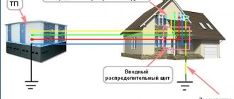
- An electric meter is installed on the facade of the building, to which a descent is made from the overhead line via a self-supporting insulated wire (the electricity supply organization is responsible for this part and for the meter).
- A voltage stabilizer(s) and a power distribution panel or automation are installed in a garage or some other room, which controls and transmits electricity through an input copper cable with a cross-section of 10–35 mm².
- A generator is installed on the street near the room where the switchboard is located, which supplies the house in the absence of a centralized power supply.
- On each floor inside the house there is a separate distribution panel, to which the input cable is connected in parallel.
- The distribution panel contains separate RCDs for the sockets of each room, circuit breakers separately for each room and separate RCDs for air conditioners, boilers, heating boilers and underfloor heating systems.
- All powerful consumers are powered strictly from the distribution panel, which provides for the installation of individual protection elements (RCD).
- A separate distribution box must be installed in each room, in which the input cables and cabling and wiring products of the socket group and lighting circuits will then be switched.
Important! When drawing up a power supply plan, it is necessary to take into account the type of supply network. If you have a 3-phase network, then the input cable to the house should have 5 mils; in the case of single-phase power supply, the number of cores of the supply cable should be 3.
Once you have decided on the power supply circuit and installation locations for electrical accessories, you can begin marking out the room.
Selection of cables and components
Today's standard wiring diagram for a private house includes two circuit breakers. One - input - is installed before the meter, usually on the street. It and the meter are sealed upon commissioning. The second RCD machine is placed in the house in front of the panel. The operation (shutdown) current of these devices is selected so that the circuit breaker installed in the house is turned off first (its current value is slightly less). Then, in the event of an emergency, you will not need to crawl under the roof.
Typical wiring diagram for a private house: there can be many different groups
If the estimated load is less than 15 kW, the circuit is standard - RCD + automatic circuit breaker, meter and then division into groups. For higher power consumption, it will be necessary to install a transformer; its parameters and the parameters of all equipment will be indicated in the project.
Recently, when connecting a private house to the power grid, they are required to install a meter and a machine on the street. This requirement is not supported by law; it is simply easier for the electricity service to control consumption. If you want, you can fight, if not, choose a meter and machine in a case with increased dust and moisture protection - a protection class of at least IP-55. For installation inside a building, the protection must be less - IP-44, and accordingly the price will be lower.
Cable selection
For electrical wiring in a private home, it is better to use cables rather than wires. Their insulation is at least twice as good, therefore the laying requirements are not so stringent, and they are safer to use. All internal wiring in a private home must be made with protective grounding. Previously, there were no such requirements, but now many electrical appliances have three-pin plugs and require grounding for safe operation. Therefore, the cable must be three-core.
In electrical cables, the cores are made of copper or aluminum. Although aluminum is cheaper, it is used less often: it is rigid, more likely to break, and more difficult to work with. If you install electrical wiring in a private home yourself and lack experience, this can become a problem. In addition, it cannot be used inside wooden houses at all.
Determination of core cross-section
Once you have decided on the material, you can select the diameter of the cable cores. This is done depending on the planned load on the line according to the table.
Calculation of electrical wiring - the selection of the cross-section of the cable cores is carried out according to this table
The cross-section of the core is selected according to the current or power of all consumers connected to one circuit breaker. This is where your home electrification plan, where you have outlined consumer groups, will come in handy once again. You calculate the sum of the currents or powers of all devices and select the desired cross-section of the cores according to the table.
How to use the table? If you decide to lay copper wires, the input voltage is 220 V, then the left part, the corresponding column, is suitable for internal wiring. The found power of all consumers connected to the group will be compared (it is easier to find and calculate). In the part where we are talking about copper wires laid in trays, voids, channels, in the “220 V” column, find the nearest higher value. Follow this line to the right to the column “Section, sq. mm". The number indicated here will be the required core size. From conductors of this diameter it will be necessary to make electrical wiring from the machine to sockets or switches.
In order not to get confused when counting and laying, designate wires of the same diameter on the plan with a certain color (write it down so as not to forget what color you designated what). After the diameter has been determined for all consumer groups, the length of the required cables for each size is calculated, and a margin of 20-25% is added to the found figures. You have calculated the wiring for your home.
Shell type selection
There are certain requirements for the type of sheath only when laying electrical wiring in wooden houses: it is recommended to use triple (NYM) or double (VVG) cable insulation. In houses of less flammable materials, any insulation can be used. The main thing is that it is intact, without cracks, sagging or other damage. If you want to play it safe, you can use conductors with enhanced protection. This makes sense in rooms with high humidity (kitchen, bathroom, swimming pool, bathhouse, etc.).
Selection of sockets and switches
For some powerful devices, sockets are selected according to the maximum (starting) current. For other low-power consumers they are standard. You need to know that they exist:
- External - when the body sticks out from the wall. They are easier to install: a backing is attached to the wall, and a socket is attached to it on top. But few people use such models now, even at their dachas. The reason is aesthetic: not the most attractive sight.
- Internal. A recess is made in the wall for the electrical part, and an installation box is installed and walled up in it. The electrical part of the socket or switch is inserted inside this box.
It is indoor electrical sockets and switches that are most often used today. They are decorated in different styles and painted in different colors. They are selected mainly to match the finish, and if this is not possible, they are installed in white.
Marking the room
In order to mark the room you will need:
- ordinary building level;
- water or laser level;
- construction pencil;
- beating thread;
- roulette.
Initially, using a laser level (water level) and a tape measure, we mark the installation locations of sockets and switches. Next, using a building level or a laser level and a pencil (mark), we mark the descents from the ceiling to the sockets and switches using strictly horizontal lines for subsequent cutting.
Using a laser level, we mark on the ceiling the places where cable and conductor products will be laid for the subsequent installation of fasteners for corrugations and cable laying.
We mark the installation location of the distribution box, which should be selected in such a way that the costs of cable and wire products are minimal.
Important! When marking the ceiling, keep in mind that all cables from sockets and switches and input cables to socket groups and lighting circuits will be brought into the distribution box, therefore, when installing corrugated fasteners, it is necessary to calculate how many cables will go where.
If there is no money for the device and no circuit
In some cases, searching for wiring is a fundamental task: for example, you urgently need to make a through hole in the wall, hammer in a dowel or nail. In such cases, you can use the means at hand to understand where the wiring is located in the panel house:
- Indicator screwdriver . This method was already briefly mentioned in the previous section of our article. A conventional indicator screwdriver detects voltage, and therefore it also detects wires with thin insulation at a shallow depth without problems. You can start your search from an outlet or chandelier and move the tool along the wall to the point near which you plan to work. The accuracy of the method is very high (plus a couple of centimeters of minutes), but it cannot be called universal.
- For major or cosmetic repairs, you can simply take a closer look at the walls and look for differences in the color of the plaster. Lighter, rough stripes of a different texture are probably grooves for wires. For them, a slightly less liquid solution is most often used, and they are made much later - the difference will definitely be noticeable to the eye.
- Radio. Surprisingly, even with the help of an ordinary radio receiver you can make your own improvised wiring diagram in an apartment panel building. To do this, you need to turn on the device and tune it to a frequency of 100 kilohertz (kHz). It is in this range that cables begin to emit interference - this is where the law of unity of electric and magnetic fields works. You need to move the antenna along the wall as if it were a specialized device or an indicator screwdriver. The only drawback is that the method has low accuracy. The error can be up to ten centimeters, and therefore when working with a drill or hammer drill, it is better to retreat the same amount in order to avoid troubles.
- Microphone. In fact, the microphone is also an antenna - these devices use approximately the same operating principle, although they have different sensitivity ranges. However, in the complete absence of a tool, it will help you find a groove in a panel house and avoid unpleasant situations. You need to turn on the microphone in the recording device and turn up the speakers. Then you need to run it along the wall at a distance of 1–2 centimeters. A characteristic sign of detected wiring is a characteristic crackling sound. The accuracy of the method is no higher than that of a radio receiver. It is also supposed to make a reserve to prevent electric shock.
Wall chipping
After completing the markings, when performing hidden electrical installations, you can begin to groove the walls. To do this, you will need either an angle grinder (grinder) or a wall chaser with a vacuum cleaner (for dust-free chasing):
Initially, it is necessary to determine the depth of the groove. Let's say you are installing a cable in a corrugated cable with a diameter of 16 mm. In this case, the depth and width of the groove must be at least 20 mm. The grooves are cut according to pre-made markings.
Important! It is prohibited to make grooves at an angle or to groove load-bearing structures (crossbars, load-bearing walls, floor slabs, etc.).
Also, at the stage of wall slitting, it is necessary to make a hole for installing an internal distribution panel. Its dimensions depend on the number of modules. In most cases, a distribution panel with 24–36 modules should be installed on each floor (depending on the number of rooms and the number of household appliances).
Drilling holes for electrical outlets and distribution boxes
For this we need:
- Hammer;
- Crown for socket boxes d68;
- Crown for distribution boxes d100.
To drill holes, turn on the “drilling + drilling” mode, insert the required crown and drill the required number of holes in the pre-marked places.
Important! When installing several sockets nearby, you need to buy junction boxes, attach them to the installation site and only then drill holes. Because otherwise you will not be able to install sockets with covers that are installed under one strip.
Strobe in aerated concrete for wiring
Compliance with the rules for gating for wiring in an aerated concrete house minimizes the risk of losing the load-bearing capacity of building structures.
- The cross-section of the groove should not exceed 25 mm in width and depth.
- It is necessary to tap at a distance of >150 mm from the edge of the wall, doors and windows.
- The length of one groove should not exceed three meters.
By following these instructions, it is possible to prevent the collapse of large fragments of aerated concrete when the channels are placed too close to each other or to the edge of the aerated concrete blocks. It is necessary to lay channels only in one direction: vertical or horizontal.
Installation of cable and wire products
In most cases, with high-quality installation, all cable and wire products are laid in corrugation. This provides additional protection for the cable, simplifies installation and makes subsequent replacement possible if the cable fails without opening the walls and disrupting the repairs performed. It is also worth noting that do-it-yourself electrical wiring in a house is done in 90% of cases in a hidden way (in grooves) and very rarely in cable ducts in an open way.
What type of cable and wire products to choose
Here, of course, you need to perform a lot of calculations, but based on many years of experience, I would like to note:
- To power the lighting circuits, a 3x1.5 mm² cable (PVSng, VVGng ShVVPng) is required.
- To power the socket group of each room, a 3x2.5 mm² cable.
- To power household air conditioners, the cable is 3x2.5 mm², but if its power is more than 5 kW, then the cable cross-section must be increased to 4 mm².
- To power an electric stove and oven, the cable cross-section must be at least 4 mm².
- To power heating boilers (electric), depending on the type of power supply (single-phase or three-phase), the cable must be from 4 mm2 to 35 mm2 (depending on power). In most cases, the manufacturer writes the recommended cross-section and number of cable cores.
Important! When laying cable and wire products, each socket group must be connected from a separate RCD (precisely an RCD in accordance with the requirements of SNiP). Also from individual machines the following must be connected:
- electric floor heating systems;
- boilers;
- washing machines;
- electric stationary heaters;
- heating boilers;
- air conditioners;
- dishwashers.
What should the input cable be like?
The input cable from the meter to the house must be calculated according to the rating of the input machine (installed after the meter). But in most cases, an input cable with a cross-section of 10–16 mm2 is sufficient for a 3-phase network and 16–70 mm2 for a 1-phase supply network.
Wiring in a house made of aerated concrete - the advantages of aerated concrete blocks
Non-autoclaved gas block combines high strength and low density. Thanks to this, not only the construction of houses made of aerated concrete blocks, but also the laying of internal utility networks in them is accelerated and cheaper.
Through drilling, milling or gating of gas blocks is carried out without extra effort with a minimum set of simple tools.
Wiring in aerated concrete is laid in grooves, which are cut with electric wall chasers and cutters. The advantage of aerated concrete blocks is the ability to cut such grooves with your own hands, without the presence of expensive electrical equipment.
Cutting grooves in aerated concrete for wiring is possible with a manual wall chaser. This inexpensive tool, compared to its electric counterpart, does not require much effort or skill from the master. Consecutive longitudinal cuts from the surface of the aerated block lead to the formation of an even channel of rectangular cross-section.
The advantages of aerated concrete blocks have made this building material a leader in popularity among private and large developers. The production of aerated concrete has become one of the most promising areas of the construction industry in Russia and the CIS countries, including Kazakhstan and Uzbekistan.
Installation and wiring of the distribution box
After installing the cable and wire products, you can install distribution boxes in pre-cut holes. To securely fix them, it is necessary to use alabaster, which sets very quickly, after which you can disconnect it.
Disconnection is performed in 3 ways:
- Soldering.
- Welding.
- Terminal connection (WAGO clamps).
Important! It is better to make connections in the distribution box using color markings of the cables (blue to blue, brown to brown, yellow-green to yellow-green). This will prevent the phase from being confused with earth or grounding. In this case, the brown (white) wire is the phase, the blue (black) is the neutral, and the yellow-green is the ground.
Lighting plan
If you approach the provision of light in an apartment according to all the rules, then initially carry out the design. The lighting scheme in the apartment is based on the design of the house itself and the rooms itself, the shape of the ceiling, finishing materials, and placement of furniture. After assessing all the factors on the apartment plan drawing, you need to select the placement of light fixtures, as well as switches and sockets.
Calculation of lighting (standards and number of lamps)
To ensure proper lighting design, you need to determine what power will be optimal for a particular home. From here, an indicator such as the number of light sources and incandescent lamps needed for a certain area is calculated. According to all the rules, the light power is distributed in the following way: every 5 m2 is illuminated by a lamp with a power of 60-65 kW. Based on these indicators, it will not be difficult to correctly calculate the number of light bulbs needed for a certain room.
Let's consider an example of how many lamps are needed to illuminate a living room with an area of 15 m2. The table below shows different types of lamps.
Connection diagram
After the number of devices to provide light has been determined, they begin to formulate a lighting plan for the apartment. It displays the locations of lamps or lighting groups, as well as elements that are used to turn light sources on and off.
The type of switches used should also be noted. For example, you can set one-key or two-key. Sometimes, if the room has a large area, duplicate light switches are used. They are intended to regulate the same lighting fixture, but are located at different ends of the room.
Example of a lighting plan with redundant switches
The type of lighting - ceiling or wall - is also indicated on the diagram drawing. Be sure to mark on the diagram which control element the lighting point belongs to.
Article on the topic: Ideas for New Year's decoration of a group in kindergarten
Circuit example
Let's give an example of a light supply scheme for a one-room apartment with an area of about 40 m2. In accordance with the standards, no more than 8 lamps will be needed.
Lighting with devices in a one-room apartment can be done in the following way:
- 3 spotlights on the ceiling;
- one chandelier;
- two sconces;
- one floor lamp;
- lamp for lighting a desk.
Lighting diagram in a one-room apartment
Installation of lighting in an apartment having a similar area, but consisting of two rooms, is provided by:
- two chandeliers;
- 3-4 ceiling lamps;
- table lamp;
- two sconces and a floor lamp.
Lighting gasket
Lighting should be carried out using different types of light sources:
- Spotlights are built into a suspended or suspended ceiling.
- Conventional chandeliers are mounted in two ways: mounted on a hook in the ceiling surface or using dowels.
Wall lamps and table lamps are also used to illuminate a certain area. LED strips have also become widespread to provide additional illumination. Depending on what types of lighting fixtures will be used, the electrical wiring diagram is selected.
On video: principles of designing lighting in an apartment.
Installation and assembly of the distribution panel
After laying cables and wires, installing and connecting distribution boxes, you can begin installing the electrical distribution panel.
How many modules should the shield be installed on?
Electrical wiring in a private house involves installing a panel on each floor in private houses, cottages or dachas. However, in order to find out how many modules are needed, you first need to calculate how many consumers there will be. Let's make a calculation for the standard version, that using its example we were able to install electrical wiring in the house with our own hands.
Let's say on your floor:
- 3 rooms.
- Kitchen;
- Corridor;
- Boiler;
- Washing machine;
- Warm floor system in 3 rooms and kitchen;
- Electric stove;
- 4 air conditioners.
Based on this, you need to install in the distribution board:
- 5 single-pole circuit breakers 10 A (lighting 3 rooms, kitchen and corridor);
- 14 pieces of RCD for 16 A (3 pieces of sockets in rooms, 1 piece of kitchen sockets, 1 piece of corridor sockets, 1 piece of boiler socket, 1 piece of washing machine socket, 3 pieces of floor heating system, 4 pieces of air conditioning);
- 1 RCD 25–32 A for connecting an electric stove.
From the above calculations, we will have 35 occupied modules (30 modules occupy 15 RCDs and 5 circuit breaker modules). That is, we will need a distribution board with 36 modules. However, if you also want to connect a voltage limiter or the number of consumers will be larger, then the shield must be mounted on 48 modules.
After installing the distribution board, you can install RCDs and circuit breakers. They are easily mounted on a special DIN rail, which comes as standard with the switchboard.
Important! When disconnecting the distribution board, the phase (brown) wires must go through automatic machines or RCDs, the neutral (blue) wires must be collected on the zero bus, and the yellow-green wires must also be connected on the 2nd zero bus).
Where to put the shield
The installation location of the shield is not regulated by regulations.
There are only restrictions regarding the distance from the pipelines; it must be at least 1 meter away. Any pipes are taken into account: water supply, heating, sewerage, internal drains, gas pipelines and even gas meters. There are no restrictions on premises. Many people install a panel in the boiler room: since it’s a technical room, it makes sense to collect all communications here. The receiving authorities do not make any claims. Sometimes it is more convenient to place the shield near the front door. If the protection class meets the requirements, there should be no claims.
Determination of current strength
An important point when planning electrical wiring is the calculation of the current strength in the electrical network. Knowing this load indicator, you can accurately determine which machine and cable with the appropriate cross-section are needed.
The planned load can be calculated using the formula: Current = Total power of household appliances (W) / Network voltage (V). For example: eight 60 W lamps, 1600 W electric kettle, 350 W refrigerator, 1200 W electric oven. Mains voltage 220 V.
Result: ((8*60) +1600+350+1200)/220=16.5A. Typical home consumption does not exceed 25 Amps. Determining the size of the cable cross-section An equally important task is to determine the cross-section of the cables that will be used for wiring electricity.
The safety of your home depends on the correct choice. A mismatch between the cross-section and the load will result in overheating of the cable, which can cause a short circuit and fire. You can determine the required cable size using the table.
For example, if the estimated current is 16.5A, closed wiring using copper wires is planned, then a cable of at least 2 kV is required. mm. For 25 Amps – 4 mm2. For different distribution groups, a cable is taken in accordance with the expected load.
Due to the fact that the table indicates extremely accurate values, and in fact frequent fluctuations in current strength are observed, a certain cross-section reserve is needed. To determine the cable length, you need to measure all distances with a tape measure and add up to four meters in reserve.
| Cross-section of current-carrying conductors, mm | Copper conductors of wires and cables | |||
| Voltage 220V | Voltage 380V | |||
| Current, A | power, kWt | Current, A | power, kWt | |
| 1,5 | 19 | 4,1 | 16 | 10,5 |
| 2,5 | 27 | 5,9 | 25 | 16,5 |
| 4 | 38 | 8,3 | 30 | 19,8 |
| 6 | 46 | 10,1 | 40 | 26,4 |
| 10 | 70 | 15,4 | 50 | 33 |
| 16 | 85 | 18,7 | 75 | 49,5 |
| 25 | 115 | 25,3 | 90 | 59,4 |
| 35 | 135 | 29,7 | 115 | 75,9 |
| 50 | 175 | 38,5 | 145 | 95,7 |
| 70 | 215 | 47,3 | 180 | 118,8 |
| 95 | 260 | 57,2 | 220 | 145,2 |
| 120 | 300 | 66 | 260 | 171,6 |
A lighting panel is installed near the entrance to the apartment, into which residual current devices are installed and wires are connected. Typically, for a network of switches and lighting, it is assumed to install a 16 A RCD, 20 A sockets. An electric stove requires a more powerful installation - 32 A and is connected separately.
Which wire to use
Cables for providing electricity in an apartment must be selected according to certain criteria. It is advisable not to change anything at your own discretion, since the safe operation of the system depends on this.
Material and design
The materials used to make wires come in two varieties: aluminum and copper. Aluminum ones are inexpensive, but copper ones are much more reliable and can provide high-quality operation.
According to their structure, wires are divided into single-core and multi-core. In the first case, the material is covered with an insulation shell. The characteristics of single conductors include: they are cheap, easy to install, and have a high degree of rigidity. The latter property leads to frequent fractures of the conductor.
Craftsmen prefer to work with stranded wires. They have good resistance to twisting and bending. If the circuit involves a sharp turn, then you can be sure that the conductor will not break.
Cable cross-section for wiring in an apartment
Cable cross-section is one of the important characteristics. Its indicator directly determines whether the conductor can withstand the applied voltage. Measured in square millimeters. Thus, in aluminum conductors with a core cross-section of 1 mm2, a voltage of 8 A can be withstood. With regard to copper products, 1 mm2 can pass 10 A.
The choice of conductor cross-section must be carried out under load. It is not allowed to use wires whose cross-section is smaller than the intended load.
Core insulation thickness
Any conductor has insulation. To ensure this, plastic materials are used. The thickness of the core insulating layer is determined by the articles of regulatory documents. For example, for a conductor designed for a load of 660 V, with a cross-section of 1.5-2.5 mm2, the insulation thickness is 0.6 mm.
Shell thickness
The next point to pay attention to is the outer sheath of the cable. It is she who closes several wires of the conductor. Similar to core insulation, plastic materials are used for external insulation, but its thickness is much greater. Mostly 1.4-1.8 mm. Take into account the fact that there are permissible deviations.
Marking
On any cable there are signs called markings. It allows you to better read information about the characteristics of the product:
- The first letter indicates the material from which the outer shell of the product is made.
- The following letters can indicate properties such as the degree of tightness, flammability of the insulating layer, the presence of steel strips in the insulation, flatness or flexibility.
- The material from which the conductor is made is marked only on aluminum cables with the letter “A”. On copper products the letter of the material is not indicated.
- Additionally, you can read information about the manufacturer and date of manufacture.
Core colors
The core insulation can be of a single color, or sometimes it can be applied in a 1 mm thick strip along the entire length of the product.
The color of the core insulation characterizes the purpose of the conductor:
- the first is the phase, this is red, brown and white insulation;
- second – zero, blue;
- the third is grounding, green or green-yellow.
The process of planning lighting in a home is quite a responsible one. But if the goal is achieved with all compliance with the rules, then this will lead to an amazing result. The right light in the interior enhances the effect several times. Consumer impressions are assessed from comments found on the Internet.