Description of the nuances of assembling a 12 Volt voltage stabilizer for a car, a list of necessary parts, 3 circuit options. + TEST for self-test. We will analyze the TOP 5 questions on the topic and the TOP 3 soldering irons for boards.
TEST:
To understand whether you have sufficient information about car stabilizers, you should take a short test:
- Why install a 12-volt stabilizer on your vehicle? a) The vehicle’s network produces an inconsistent voltage. This depends on the state of charge of the battery. The voltage ranges from 11.5 - 14.5 Volts. But LED bulbs only require 12 volts. To supply the required voltage, SN is installed. b) LED lamps operate at 18 Volts. In order for them to function when connected to a car, additional load has to be supplied through a stabilizer.
- Why do LED light bulbs often burn out without a stabilizer? a) The main reason is a low-quality LED manufacturer. b) Due to surge voltage on them.
- In what case will it be necessary to additionally connect an aluminum radiator to the stabilizer? a) If more than 10 LEDs are installed on the car. b) When installing LED lamps of different colors on the car.
- How are LEDs connected? a) 3 LEDs are connected in series to a resistor, and then the assembled set is connected in parallel to the next LEDs. b) 3 LEDs are connected in parallel to a resistor, and then the assembled set is connected in series to the next LEDs.
Answers:
- a) Depending on the state of charge of the battery, the LED lamps will receive a fluctuating voltage - from 11.5 to 14.5. That is why the MV is connected to the lamps - to obtain a constant voltage of 12 Volts (this indicator is needed for LEDs).
- b) LEDs are not designed for voltage surges that come from the battery, so they soon burn out without a stabilizer.
- a) If more than 10 LEDs are installed on a car, then it is advisable to equip the circuit with an aluminum radiator.
- b) First, 3 LEDs are connected in series to a resistor, and then they take a new coupler and connect them in parallel to each other.
Car owners often install LED lighting on their cars. But light bulbs quite often fail, and all the created beauty immediately fades. This is because LED bulbs do not work properly if they are simply connected to an electrical outlet. For them it is necessary to use special stabilizers. Only in this case will the lamps be protected from voltage surges, overheating, and breakdown of important components. To install a voltage stabilizer on your car, you need to understand this issue in detail and study a simple circuit that you can assemble with your own hands.
Definition: CH 12 volt for a car is a small device designed to dampen excess voltage in a car coming from the battery. As a result, the connected LED lamps receive a constant load of 12 volts.
Selection of 12 V stabilizer
The car's on-board network provides power from 13 V, but LEDs need only 12 V to operate. That is why it is necessary to install a voltage stabilizer, which will provide exactly 12 V at the output.
By installing such equipment, it will ensure normal conditions for the operation of LED lighting, which will not fail for a long time. When choosing stabilizers, motorists are faced with problems, since there are so many designs, and they all work differently.
You should select a stabilizer that:
- It will function correctly.
- Provides reliable protection and safety of lighting equipment.
Video
Adjustable voltage stabilizer
Coffee capsule Nescafe Dolce Gusto Cappuccino, 3 packs of 16 capsules
1305 ₽ More details
Coffee capsules Nescafe Dolce Gusto Cappuccino, 8 servings (16 capsules)
435 ₽ More details
Photo printers
A simple 12 V voltage stabilizer with your own hands
If you have even minor skills in assembling an electrical circuit, then it is not necessary to purchase a voltage stabilizer ready-made. To make a homemade device, a person will spend 50 rubles or less; a ready-made model costs slightly more. There is no point in overpaying, since the result will be a high-quality device that meets all the necessary requirements.
The simplest but most functional stabilizer can be made with your own hands without much effort. It is very difficult to assemble a pulse device, especially for a beginner, and therefore it is worth considering linear stabilizers and amateur circuits for it.
The simplest 12 volt voltage stabilizer is assembled from a (finished) circuit, as well as a resistance resistor. It is advisable to use the LM317 chip. All parts will be attached to a perforated panel or universal printed circuit board. If you assemble the device correctly and connect it to your car, you can provide good lighting - the lights will stop blinking.
LM317 circuit
Connection diagram
Connection diagram based on LM2940CT-12.0
The stabilizer body can be made of almost any material except wood. When using more than ten LEDs, it is recommended to attach an aluminum radiator to the stabilizer.
Maybe someone has tried it and will say that you can easily do without unnecessary troubles by directly connecting the LEDs. But in this case, the latter will be in unfavorable conditions most of the time, and therefore will not last long or will burn out altogether. But tuning expensive cars results in a fairly large sum.
As for the described schemes, their main advantage is simplicity. Manufacturing does not require any special skills or abilities. However, if the circuit is too complex, then assembling it with your own hands becomes unreasonable.
12V MV Parts List
To make a voltage stabilizer with your own hands, you should find or buy the following parts:
- Board - 35 by 20 mm.
- Chip LD 1084.
- RS407 diode bridge. If this is not the case, then we select any small diode intended for reverse current.
- Power supply with a transistor and two resistances. This equipment is needed to ensure that the end is turned off when the low or high beam headlights are turned on.
Three LEDs must be connected in series with a current-limiting resistor that equalizes the electric current. This set should then be connected in parallel to the next set of light bulbs.
Connection diagram
The LM7812 itself is a voltage stabilization circuit and the device is usually connected to it only for this purpose. In fact, nothing else is required to perform this function. Beginning radio amateurs use it in their developments without additional strapping and it works for them, but this is not entirely the right solution.
It is advisable to follow the manufacturers' recommendations, which provide a 7812 switching circuit using two capacitors of 25 V or more. They must be soldered as close to the contacts as possible for more stable operation of the microcircuit. In this case, more capacitance is required at the input than at the output. Failure to comply with this rule leads to instability of the output voltage when there is a sudden change in the load. In addition, such capacitive piping performs protective functions against self-excitation.
The passport states that it is permissible not to install a smoothing capacitor at the output at all. This is possible due to the fact that the role of the power control element inside the 78xx series is performed by an emitter follower based on a Darlington transistor. But as practice shows, a small capacitance is still installed for better suppression of output high-frequency ripples.
An example of how such a scheme works can be seen in a short video.
How to make a 12-volt voltage stabilizer for LEDs in a car using the L7812 chip
To assemble a high-quality voltage stabilizer, you can use a three-pin DC voltage regulator, available in the L7812 series. This device will power not only individual light bulbs in a car, but also an entire strip of LEDs.
L7812
Components:
- Chip L7812.
- Capacitor 330 uF 16 V.
- Capacitor 100 uF 16 V.
- 1 amp rectifier diode. You can use a 1n4001 or a Schottky diode.
- Heat shrink 3 mm.
- Connecting wires.
Assembly order:
- We slightly shorten one leg of the stabilizer.
- We use solder.
- We add a diode to the short leg, and then capacitors.
- We place heat shrink on the wires.
- We are soldering wires.
- We put on the heat shrink and press it with a hair dryer or a lighter. It is important not to overdo it and not melt the heat shrink.
- We supply power to the input on the left side, and on the right there will be an output to the LED strip.
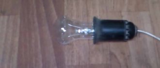
- We carry out a test - turn on the lighting. The tape should light up, its service life will now increase.
This is how you make a 12V voltage stabilizer with your own hands.
Types of 12V stabilizers
Such devices can be assembled using transistors or integrated circuits. Their task is to ensure the value of the rated voltage Unom within the required limits, despite fluctuations in the input parameters. The most popular schemes are:
- linear;
- impulse.
The linear stabilization circuit is a simple voltage divider. Its work lies in the fact that when Uin is applied to one “arm,” the resistance changes on the other “arm.” This keeps Uout within the specified limits.
Important! With such a scheme, if there is a large spread of values between the input and output voltages, the efficiency drops (a certain amount of energy turns into heat), and the use of heat sinks is required. Pulse stabilization is controlled by a PWM controller
By controlling the key, he regulates the duration of the current pulses. The controller compares the value of the reference (set) voltage with the output voltage. The input voltage is supplied to the switch, which, opening and closing, supplies the received pulses through a filter (capacitance or inductor) to the load
Pulse stabilization is controlled by a PWM controller. By controlling the key, he regulates the duration of the current pulses. The controller compares the value of the reference (set) voltage with the output voltage. The input voltage is supplied to the switch, which, opening and closing, supplies the received pulses through a filter (capacitor or inductor) to the load.
For your information. Switching voltage stabilizers (SV) have higher efficiency and require less heat removal, but electrical impulses during operation create interference for electronic devices. Self-assembly of such circuits has significant difficulties.
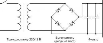
Classic stabilizer
Such a device includes: a transformer, a rectifier, filters and a stabilization unit. Stabilization is usually carried out using zener diodes and transistors.
The main work is done by the zener diode. This is a kind of diode that is connected to the circuit in reverse polarity. Its operating mode is breakdown mode. The principle of operation of the classic CH:
- when Uin < 12 V is supplied to the zener diode, the element is in the closed state;
- when Uin > 12 V enters the element, it opens and holds the declared voltage constant.
Attention! A supply of Uin exceeding the maximum values specified for a certain type of zener diode leads to its failure. Diagram of a classic linear CH
Diagram of a classic linear CH
Integral stabilizer
All structural elements of such devices are located on a silicon chip, the assembly is enclosed in an integrated circuit (IC) package. They are assembled on the basis of two types of ICs: semiconductor and hybrid film. The former have solid-state components, the latter are made of films.
Main! Such parts have only three terminals: input, output and adjustment. Such a microcircuit can produce a stable voltage of 12 V with an interval of Uin = 26-30 V and a current of up to 1 A without additional wiring.
CH circuit on IC
It is also important to know 3 nuances on how to assemble a 12 volt voltage stabilizer with your own hands
- It is advisable to connect LEDs through a current stabilizer. In this way, it will be possible to balance the fluctuations in the electrical network, and the car owner will not worry about current surges.
- The power supply requirements must also be observed, since, in this way, your self-assembled stabilizer can be correctly adjusted to the electrical network.
- It is advisable to assemble a unit that will provide decent stability, reliability and stability - the stabilizer should last for many years. That’s why you shouldn’t cheap out on components – buy them in good electronics stores.
Schemes of simple stabilizers
Easy about simple things. Current strength, voltage and their stabilization
Voltage determines how quickly electrons move through a conductor. Many passionate fans of hard computer overclocking increase the voltage of the central processor core, making it start to function faster.
Current strength is the density of electron movement within an electrical conductor. This parameter is extremely important for radioelements operating on the principle of thermionic secondary emission, in particular, light sources. If the cross-sectional area of the conductor is not able to pass the flow of electrons, excess current begins to be released in the form of heat, causing significant overheating of the part.
Plasma arc from high voltage
To better understand the process, let’s analyze the plasma arc (electric ignition of gas stoves and boilers works on its basis). At very high voltages, the speed of free electrons is so high that they can easily “fly” the distance between the electrodes, forming a plasma bridge.
And this is an electric heater. When electrons pass through it, they transfer their energy to the heating element. The higher the current, the denser the flow of electrons, the more the thermoelement heats up.
How to avoid 3 mistakes when soldering a circuit
- Before starting all soldering work, be sure to select the most suitable soldering machine for assembling the microcircuit. The old one lying at home or in the garage is suitable only for experienced people, but a beginner will ruin the board, unable to cope with the power. The most suitable voltage range for connecting boards and wiring is 15-30 watts. We don’t use more power, otherwise the board will burn out and you’ll have to start all over again with new parts.
- Before you start connecting parts by soldering, make sure that the circuit is well cleaned. For high-quality processing, a simple composition is used - any soap is mixed with clean water. Afterwards, a clean napkin is dipped into the prepared solution and the board is wiped very efficiently over the entire surface. If there are traces of soap left on the metal, wipe them off carefully with a dry cloth. Quite dense deposits are often noticed on boards. To get rid of them, you will have to go to an electrical store and buy a special cleaning composition. The sellers will tell you everything you need. We process the area until a slight metallic sheen appears.
- We place the contacts on the board in the correct sequence - first we work with small resistors, and then move on to large parts. If you first attach all the large parts, then the small parts will become very inconvenient to attach - large components will get in the way.
Don't neglect the advice. They will allow you to create a better connection, and hence the durability of the stabilizer.
Circuits of stabilizers and current regulators
Everyone knows that LED light bulbs require twelve volts of power. In a car network, this value can reach up to 15 V. LED elements are very sensitive, such surges are reflected negatively on them. LED lamps may burn out or produce poor quality light (flash, lose brightness, etc.).
To make the LEDs last longer, drivers (resistors) are included in the car's electrical network. When there is instability in the network, devices are installed that maintain a constant value. There are several simple microcircuits that you can use to make a voltage stabilizer with your own hands. All components included in the chain can be purchased at specialized stores. Having basic knowledge of electrical engineering, making devices will not be difficult.
On Krenka
In order to construct a simple 12 volt voltage stabilizer with your own hands, you will need a microcircuit with a consumption of 12 V. In this case, an adjustable 12 V voltage stabilizer LM317 is suitable. It can operate in an electrical network where the input parameter is up to 40 V. In order for the device to operate stably, it is necessary to provide cooling.
Chip rolls
The current regulator on the LM317 requires a small current of up to 8 mA to operate, and this value usually remains the same even when large current flows through the LM317 bank or when the input value changes. This is implemented using the R3 component.
You can use the R2 element, but the limits will be small. If the resistance of LM317 remains constant, the current flowing through the device will also be stable (author of the video - Created in Garage).
The input value for the LM317 bank can be up to 8 mA and higher. Using this microcircuit, you can come up with a current stabilizer for DRLs. This device can act as a load in the on-board network or a source of electricity when recharging the battery. Making a simple voltage regulator LM317 is not difficult.
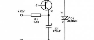
On two transistors
Today, stabilizing devices for the on-board network of a 12 V car, developed using two transistors, are popular. This microcircuit is used as a voltage stabilizer for DRLs.
Resistor R2 is a current-distributing element. As the current in the network increases, the voltage increases. If it reaches a value from 0.5 to 0.6 V, element VT1 opens. Opening component VT1 closes element VT2. As a result, the current passing through VT2 begins to decrease. You can use a Mosfet field-effect transistor together with VT2.
Element VD1 is included in the circuit when the values are in the range from 8 to 15 V and are so large that the transistor may fail. With a powerful transistor, readings in the on-board network of about 20 V are acceptable. Do not forget that the Mosfet transistor will open if the readings at the gate are 2 V.
On an operational amplifier (op-amp)
A voltage stabilizer for LEDs based on an op-amp is assembled if it is necessary to create a device that will operate in an extended range. In the case under consideration, the element that will set the rectified current is R7. Using the DA2.2 operational amplifier, you can increase the voltage level in the current-setting component. The task of the DA 2.1 component is to control the reference voltage.
When creating the circuit, you should take into account that it is designed for 3A, so more current is required, which must be supplied to the XP2 connector. In addition, the functionality of all components of this device should be ensured.
The made stabilizing device for a car must have a generator, the role of which is performed by REF198. To properly configure the device, the slider of resistor R1 must be set to the upper position, and resistor R3 must be used to set the required value of the rectified current 3A. To suppress possible excitations, elements R,2 R4 and C2 are used.
On a pulse stabilizer chip
If a rectifier for a car must provide high efficiency in the network, it is advisable to use switching components, creating a switching voltage stabilizer. The MAX771 circuit is popular.
Switching rectifier circuit
The switching current stabilizer is characterized by an output power of 15 W. Elements R1 and R2 divide the output of the circuit. If the divided voltage exceeds the reference voltage, the rectifier automatically reduces the output value. Otherwise, the device will increase the output parameter.
Assembly of this device is advisable if the level exceeds 16 V. R3 components are current. To eliminate the high load drop across this resistor, an op-amp should be included in the circuit.
TOP 3 soldering irons for circuit boards
To simplify the work of soldering the stabilizer, it is advisable to buy a high-quality soldering iron. The stores have units from good and trusted manufacturers that you should pay attention to:
- Ersa is a German company. The product is very good and reliable, but expensive, and therefore not everyone can afford it for their home.
- Chinese company Quick. The quality is excellent and the price is reasonable.
- Luckey. The most budget option. Do not leave the device turned on unattended - it may cause a fire.
A 10 W soldering iron is enough to make a simple microboard. When purchasing, examine the handle - it should not heat up quickly. Wood is an ideal option. Plastic will quickly become hot, hard rubber is heavy, and therefore difficult to work with small parts.
It is advisable to choose a tip made of copper - it is easy to clean off carbon deposits after work. The stings come in different shapes and are sold in sets. This will not be useful for a beginner, but experienced people will find it convenient to use attachments of different configurations.
Voltage stabilizers for cars
Device selection
Voltage stabilizer 12 volts
When choosing a stabilizer, take into account the following characteristics:
- Dimensions. The selected stabilizer must be compactly placed in its planned installation location with normal access.
- View. Of the commercially available devices, the most reliable, compact and inexpensive are stabilizers based on small microcircuits.
- Possibility of self-repair. Since even the most reliable devices fail, it is necessary to give preference to repairable stabilizers, radio components for which are commercially available in sufficient quantities and at an affordable price.
- Reliability. The selected stabilizer must provide a constant voltage value without significant deviations from the range declared by their manufacturer.
- Price. For the electrical system of a car, it is enough to purchase a device costing up to 200 rubles.
Brief description of lm317
The LM317 radio-electronic module is a microcircuit used in current and voltage stabilization systems.
- The voltage stabilization range from 1.7 to 37 V will ensure stable LED brightness, independent of engine speed;
- Support for output current up to 1.5 A allows you to connect several photo emitters;
- High stability allows fluctuations in output parameters of only 0.1% of the nominal value;
- Has built-in current limiting protection and a shutdown cascade for overheating;
- The microcircuit body is ground, so when fastened with a self-tapping screw to the car body, the number of mounting wires is reduced.
Application area
- Voltage and current stabilizer for LEDs in domestic conditions (including for LED strips);
- Voltage and current stabilizer for LEDs in cars;