1.7.55
For grounding in electrical installations of different purposes and voltages that are geographically close, one should, as a rule, use one common grounding device.
A grounding device used for grounding electrical installations of the same or different purposes and voltages must meet all the requirements for the grounding of these electrical installations: protecting people from electric shock when the insulation is damaged, operating conditions of networks, protecting electrical equipment from overvoltage, etc. during the entire period of operation.
First of all, the requirements for protective grounding must be met.
Grounding devices for protective grounding of electrical installations of buildings and structures and lightning protection of categories 2 and 3 of these buildings and structures, as a rule, should be common.
When installing a separate (independent) grounding system for working grounding under the operating conditions of information or other equipment sensitive to interference, special measures must be taken to protect against electric shock, preventing simultaneous contact with parts that may be exposed to a dangerous potential difference if the insulation is damaged.
To combine grounding devices of different electrical installations into one common grounding device, natural and artificial grounding conductors can be used. Their number must be at least two.
The difference between working grounding and protective grounding
Working grounding. The principle of operation is to connect several separate objects of the building's electrical circuit to the ground. This could be the neutral winding of a generator, or other various devices.
It is designed to ensure the correct operation of the electrical installation, regardless of the conditions of its use. This type of protection is implemented by directly connecting the grounded enclosures of electrical installations with grounding conductors.
Quite rarely, working grounding can be carried out using specialized devices - these can be breakdown fuses or resistors.
Protective grounding and grounding, as mentioned above, performing work on electrical connections with metal non-current-carrying parts of devices. In this case, the main job of the protective circuit is to prevent electrical injuries when a person touches the equipment body, because the current from it is diverted to the grounding circuit, the resistance of which is less than the resistance of the human body.
Therefore, the difference between these two protective devices is the principle of their operation. If the working one equalizes the potentials, then the protective one diverts the current to the grounding circuit, as a rule, along a solidly grounded neutral.
But when equipping your premises with any type of protection, the greatest operational efficiency will be achieved provided that short-circuit currents do not increase due to a decrease in the level of grounding resistance.
Something else to keep in mind. No grounding circuit will be able to perform the work of current circuit breakers and residual current leakage devices. And these devices will not be able to perform their work reliably without protective grounding.
1.7.54
For grounding electrical installations, artificial and natural grounding conductors can be used. If, when using natural grounding conductors, the resistance of the grounding devices or the touch voltage has an acceptable value, and the normalized voltage values on the grounding device and the permissible current densities in natural grounding conductors are ensured, the implementation of artificial grounding conductors in electrical installations up to 1 kV is not necessary. The use of natural grounding conductors as elements of grounding devices should not lead to their damage when short-circuit currents flow through them or to disruption of the operation of the devices with which they are connected.
Rules for installing a portable view
Portable grounding is installed during temporary maintenance or repair of electrical equipment. Installation of protective grounding is permitted only after checking that there is no voltage in the circuit.
Protective grounding, designed to protect personnel working on the line from electric shock in the event of erroneous switching on of voltage, must be installed on all disconnected phases, from all sides from which voltage can be supplied.
Installation of portable grounding in electrical installations with a voltage of more than 1000 Volts is permitted to be carried out by personnel with an electrical safety group of at least fourth, and in installations up to 1000 Volts - not lower than third.
It is prohibited to use parts that are not intended for this purpose as grounding elements; it is also prohibited to connect grounding elements by twisting.
1.7.54
For grounding electrical installations, artificial and natural grounding conductors can be used. If, when using natural grounding conductors, the resistance of the grounding devices or the touch voltage has an acceptable value, and the normalized voltage values on the grounding device and the permissible current densities in natural grounding conductors are ensured, the implementation of artificial grounding conductors in electrical installations up to 1 kV is not necessary. The use of natural grounding conductors as elements of grounding devices should not lead to their damage when short-circuit currents flow through them or to disruption of the operation of the devices with which they are connected.
Principle of operation
It is usually installed for protection in the event of a short circuit. If a phase conductor becomes disconnected and touches the metal chassis of the installation, the housing will be energized.
A properly created protective ground creates an electrical circuit that has low resistance. It is this path that is most favorable for electric current, so accidental human touch to the body will not be dangerous (Fig. above).
It should be noted that such a device will simultaneously perform several important functions:
- It will also provide protection in the case when potentially dangerous voltage on the housing is formed not by a short circuit, but by induced currents. Such situations are possible in installations with high voltage and where exposure to microwave radiation is permissible. When using a solidly grounded neutral and some other connection schemes in the power circuit during a short circuit, long-lasting and large-amplitude pulses will occur, sufficient to trigger circuit breakers that turn off the voltage. If the grounded If the equipment is subject to a lightning strike, such a conductor will provide some protection from damage.
Using this formula, the resistance of the protective circuit conductor between the main busbar and the distribution panel is calculated: 50 x SFN/LV. STSFN – resistance in the zero-phase circuit; LV – nominal voltage in volts.
In order not to make mistakes with terminology, you need to understand the real meaning of the following names:
Working is called grounding, which performs the functions of the second conductor.
It is used to power installations and solve other problems. The lightning protection mentioned above is not the intended purpose. To ensure safety during thunderstorms, specially designed devices are used. They are designed for relatively large currents and voltages.
1.7.93
It is not recommended to connect the external fence of electrical installations to a grounding device.
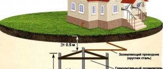
If overhead lines of 110 kV and higher depart from the electrical installation, then the fence should be grounded using vertical grounding conductors 2-3 m long, installed at the fence posts along its entire perimeter every 20-50 m. Installation of such grounding conductors is not required for a fence with metal posts and with those posts made of reinforced concrete, the reinforcement of which is electrically connected to the metal links of the fence.
To exclude electrical connection of the external fence with the grounding device, the distance from the fence to the elements of the grounding device located along it on the internal, external or both sides must be at least 2 m. Horizontal grounding conductors, pipes and cables with a metal sheath or armor and other metal communications must be laid in the middle between the fence posts at a depth of at least 0.5 m. In places where the external fence adjoins buildings and structures, as well as in places where internal metal fences adjoin the external fence, brick or wooden inserts of length not less than 1 m.
Power supply to electrical receivers installed on the external fence should be supplied from isolation transformers. These transformers are not allowed to be installed on a fence. The line connecting the secondary winding of the isolation transformer with the power receiver located on the fence must be insulated from the ground to the calculated voltage value on the grounding device.
If it is impossible to carry out at least one of the indicated measures, then the metal parts of the fence should be connected to a grounding device and potential equalization should be performed so that the touch voltage on the outer and inner sides of the fence does not exceed permissible values. When making a grounding device according to the permissible resistance, for this purpose a horizontal grounding conductor must be laid on the outside of the fence at a distance of 1 m from it and at a depth of 1 m. This grounding conductor should be connected to the grounding device at at least four points.
Monitoring the status of protective devices
Electrical installation rules require periodic testing of the grounding system. It allows you to establish compliance of the parameters of the resistance to current drainage of the grounding loops with the normative ones. The test takes place using special measuring instruments connected to grounding devices according to certain circuits.
The rules also regulate the frequency of inspections. It depends on the inspection class, the design of grounding devices, the type and power of the equipment used. A visual inspection of the condition of the grounding system should be carried out every six months. Inspections accompanied by excavation of the soil in areas associated with increased risk - once every 12 years or more often.
A competent approach to organizing the grounding system for electrical installations, a clear understanding of the structure and features of different types of installations, as well as timely monitoring of their condition, in accordance with current regulations, will ensure the safety of enterprise employees, the safety of equipment and buildings.
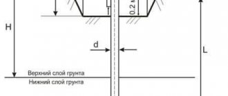
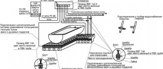
Rules for grounding pipelines
Grounding of pipelines is a mandatory measure, enshrined in the PUE. This is how you can increase the safety of their operation, because static electricity accumulates in pipe systems, plus there is always the possibility of lightning striking the pipes. The requirements of the rules for the construction of electrical installations are to provide grounding not only for external pipelines, but also for internal ones (technological and communication).
The PUE clearly regulates how pipelines should be grounded.
- Firstly, the pipe system must be a single continuous network connected into a single circuit.
- Secondly, pipelines must be connected to the grounding system at at least two points.
As for the first position, this does not mean that the pipeline system itself must be continuous. Here it will be enough to ensure the connection of sections or individual pipelines into one single network, for which so-called wafer jumpers are most often used. In fact, this is an ordinary copper wire of the brand either PVZ or PuGV. Fastening of jumpers to the pipeline is ensured by welding, bolting, or a grounding clamp for pipes is installed.
As for the second position, experts recommend not to scatter along the entire line of the technological chain, just to make a connection at the beginning and end of the circuit.
1.7.68
Fences and shells in electrical installations with voltages up to 1 kV must have a degree of protection of at least IP 2X, except in cases where large clearances are necessary for the normal operation of electrical equipment.
Guards and shells must be securely fastened and have sufficient mechanical strength.
Entering the fence or opening the shell should be possible only with the help of a special key or tool, or after removing the voltage from live parts. If these conditions cannot be met, intermediate barriers with a degree of protection of at least IP 2X must be installed, the removal of which must also be possible only with the help of a special key or tool.
4.2.134
Open switchgear and substations of 20-750 kV must be protected from direct lightning strikes. Protection against direct lightning strikes is not required for 20 and 35 kV substations with transformers with a unit capacity of 1.6 MVA or less, regardless of the number of such transformers and the number of thunderstorm hours per year, for all outdoor switchgear of 20 and 35 kV substation in areas with thunderstorm hours per year are no more than 20, as well as for outdoor switchgear and substation 220 kV and below at sites with an equivalent earth resistivity during the thunderstorm season of more than 2000 Ohm m with the number of thunderstorm hours per year not more than 20.
Buildings of closed switchgear and substations should be protected from direct lightning strikes in areas with more than 20 thunderstorm hours per year.
The protection of closed switchgear and substation buildings with metal roof coverings should be carried out by grounding these coverings. If there is a reinforced concrete roof and continuous electrical connection of its individual elements, protection is carried out by grounding its reinforcement.
The protection of closed switchgear and substation buildings, the roof of which does not have metal or reinforced concrete coverings with continuous electrical connection of its individual elements, should be carried out with rod lightning rods, or by laying a lightning protection mesh directly on the roof of the buildings.
When installing rod lightning rods on a protected building, at least two down conductors must be laid from each lightning rod on opposite sides of the building.
The lightning protection mesh must be made of steel wire with a diameter of 6-8 mm and laid on the roof directly or under a layer of non-combustible insulation or waterproofing. The grid should have cells with an area of no more than 150 m (for example, a cell 12x12 m). The mesh nodes must be connected by welding. Down conductors connecting the lightning protection grid to the grounding device must be laid at least every 25 m around the perimeter of the building.
Metal and reinforced concrete (if there is at least part of the unstressed reinforcement) building structures should be used as down conductors. In this case, a continuous electrical connection from the lightning rod to the ground electrode must be ensured. Metal elements of the building (pipes, ventilation devices, etc.) should be connected to a metal roof or lightning protection mesh.
When calculating the number of reverse overlaps on a support, one should take into account the increase in the inductance of the support in proportion to the ratio of the distance along the down conductor from the support to the grounding to the distance from the grounding to the top of the support.
When entering into closed switchgears and substations of overhead lines through bushings located at a distance of less than 10 m from current conductors and other associated live parts, these inputs must be protected by RF or appropriate surge arresters. When connecting to the substation grounding mains at a distance of less than 15 m from power transformers, the conditions of 4.2.136 must be met.
For electrolysis buildings located on the territory of the substation, premises for storing hydrogen cylinders and installations with hydrogen receivers, the lightning protection mesh must have cells with an area of no more than 36 m (for example, 6x6 m).
Protection of buildings and structures, including explosive and fire hazardous ones, as well as pipes located on the territory of power plants, is carried out in accordance with technical documentation approved in the prescribed manner.
Calculation rules
Calculation of protective grounding must be carried out in order to correctly determine the parameters of the grounding loop, such as its type, shape, area, dimensions, number of grounding conductors and the distance between them. All these parameters, together with the soil conductivity value, directly affect the total resistance value of the grounding system.
It is mandatory to calculate the grounding device before starting installation of the circuit.
When calculating protective grounding, pay special attention to the value of the earth's resistivity. For calculations, it is necessary to take the value that corresponds to the most unfavorable seasonal conditions.
1.7.83
The additional potential equalization system must connect with each other all simultaneously accessible open conductive parts of stationary electrical equipment and third-party conductive parts, including accessible metal parts of building structures, as well as neutral protective conductors in the system and protective grounding conductors in systems and, including protective conductors of plug sockets
For potential equalization, specially provided conductors or exposed and third-party conductive parts may be used if they satisfy the requirements of 1.7.122 for protective conductors with regard to conductivity and continuity of the electrical circuit.
Definition of the concept
To put it briefly and in simple words:
Grounding is a device that protects a person from electric shock if all electrical equipment is connected to ground. In an emergency situation, dangerous voltage “drains” to the ground.
Protection is the main purpose of grounding. It consists of connecting an additional, third grounding conductor to the wiring, which is connected to a device such as a ground electrode. He, in turn, has good contact with the ground.
Grounding can be operational or protective according to its intended purpose.
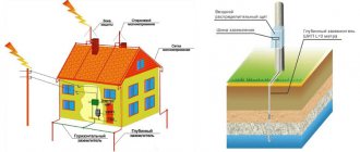
The working one is needed for the normal functioning of the electrical installation, the protective one is needed to ensure electrical safety (preventing electric shock). Typically, grounding (ground electrode) looks like three electric rods driven into the ground, at the same distance from each other, located in the corners of an equilateral triangle. These rods are connected to each other by a metal strip. You might have seen such rods near houses and buildings.
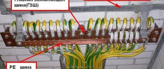
You may also have noticed that on the walls of many buildings, inside or outside, metal strips are fixed, sometimes painted with yellow and green alternating stripes - this is a grounding bus, it is also connected to a ground electrode. A grounding bus is needed so as not to pull a grounding wire from each electrical installation.
The third conductor is usually connected to the frame of electrical devices, providing protection against dangerous voltage. In cables, it usually has a smaller cross-section than the adjacent “working” conductors and a different insulation color – yellow-green.
You can learn about what types of grounding there are from our separate article: https://samelectrik.ru/osnovnye-tipy-sistem-zazemlenija.html
1.7.100
In electrical installations with a solidly grounded neutral, the neutral of a three-phase alternating current generator or transformer, the midpoint of a direct current source, one of the terminals of a single-phase current source must be connected to the grounding conductor using a grounding conductor.
An artificial ground electrode designed to ground the neutral, as a rule, should be located near the generator or transformer. For intra-shop substations, it is allowed to place the ground electrode near the wall of the building.
If the foundation of the building in which the substation is located is used as natural grounding, the neutral of the transformer should be grounded by connecting to at least two metal columns or to embedded parts welded to the reinforcement of at least two reinforced concrete foundations.
When built-in substations are located on different floors of a multi-story building, the grounding of the neutral of the transformers of such substations must be carried out using a specially laid grounding conductor. In this case, the grounding conductor must be additionally connected to the building column closest to the transformer, and its resistance is taken into account when determining the spreading resistance of the grounding device to which the transformer neutral is connected.
In all cases, measures must be taken to ensure continuity of the grounding circuit and protect the grounding conductor from mechanical damage.
If in PEN
- the conductor connecting the neutral of the transformer or generator with the
PEN
bus of the switchgear with voltage up to 1 kV has a current transformer installed, then the grounding conductor should not be connected to the neutral of the transformer or generator directly, but to the
PEN
conductor, if possible immediately after the current transformer.
In this case, the division of the PEN
conductor into
PE
and conductors in the system must also be carried out behind the current transformer. The current transformer should be placed as close as possible to the neutral terminal of the generator or transformer.
Requirements for protective grounding
Protective grounding is a more rigid device than circuit grounding. It provides for the laying of a separate bus, a fairly low level of resistance, which goes to a system of grounding conductors driven into the ground in the form of a triangle.
Calculation of protective grounding requires knowledge of many formulas and the availability of many initial data. Therefore, it is customary for residential buildings to use standard ground loop designs for each region.
The grounding installation involves laying a neutral bus or any other method of draining current in a single-phase circuit. In this case, the resistance values of each grounding conductor to the substation or supply transformer, adding up, form the resistance value of the protective device.
This value may vary, but the requirements for protective grounding and grounding provide for the general value of the maximum possible level of circuit resistance.
Household grounding
As a rule, power supply systems must have a protective grounding resistance of 4 ohms to 30 ohms. For arrangement, as a rule, steel corners and a strip 40 mm wide are used. Provide for the use of a copper busbar of sufficient cross-section, in accordance with GOST. This is a mandatory requirement.
When using a protective conductor with a 0.5 mm2 copper wire, even 100 meters of wire is not enough to reach the critical value. The most stringent requirements are imposed when servicing areas:
- Installations with a circuit voltage of up to 1000 V are equipped with a device whose resistance should not exceed 0.5 Ohm. The value of the grounded loop is measured using a special measuring device - a resistance meter. This measurement is carried out by two additional ground electrodes. Having separated them to a certain distance, we take measurements, then moving the electrode, we take several measurements. The worst result is taken as the nominal value.
- To service the transformer circuit and other power sources, at voltages from 220 V to 660 V, the grounding resistance value must be from 2 Ohms to 8 Ohms.
1.7.77
It is not necessary to intentionally connect to the source neutral in the system and ground in systems and:
1) housings of electrical equipment and devices installed on metal bases: structures, switchgears, switchboards, cabinets, frames of machines, machines and mechanisms connected to the neutral of the power source or grounded, while ensuring reliable electrical contact of these housings with the bases;
2) structures listed in 1.7.76, while ensuring reliable electrical contact between these structures and the electrical equipment installed on them, connected to the protective conductor;
3) removable or opening parts of the metal frames of switchgear chambers, cabinets, fences, etc., if electrical equipment is not installed on the removable (opening) parts or if the voltage of the installed electrical equipment does not exceed the values specified in 1.7.53;
4) reinforcement of insulators of overhead power lines and fasteners attached to it;
5) open conductive parts of electrical equipment with double insulation;
6) metal staples, fasteners, sections of pipes for mechanical protection of cables in places where they pass through walls and ceilings and other similar parts of electrical wiring with an area of up to 100 cm, including broach and branch boxes of hidden electrical wiring.
Connection diagrams
To choose the best option, you need to know for what purpose protective grounding is used in a particular case. The different systems, their features, advantages and disadvantages are discussed below.
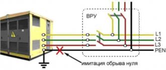
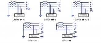
Type TN, with solidly grounded neutral.
According to this scheme, industrial and household equipment operating in networks with voltages up to and above 1000 V is connected. The neutral of the generator (transformer) of the power source is connected to the grounding electrode. Consumer devices, or rather housings, screens, chassis, are connected to a common conductor.
If the electrical circuit is created in accordance with international standards, then the following can be understood from the inscriptions. The Latin letter “N” denotes the “neutral” conductor, which is used to operate the equipment.
That's what they call functional. “PE” is a conductor used to create a protective circuit. The letters “PEN” denote a conductor designed to solve functional and protective problems.
The following schemes are most often used. Their names are distinguished by the letter that is added to “TN” through a hyphen.
Connection diagrams
SystemPrinciple of operationAdvantages, disadvantages, featuresIn the “C” system, the conductor performs working and protective functions simultaneously. As an example, we can recall a typical three-phase power supply with a solidly grounded neutral, which is the neutral wire. This circuit is relatively simple and economical. The housings of consumer devices are connected directly to the neutral.
The disadvantage is the loss of protective properties if the electrical circuit is broken. Such damage cannot be excluded due to an emergency increase in current, heating and destruction of the conductor. In such a situation, dangerous voltage will appear on the housing.
When using such systems, automatic machines are especially carefully selected, which must quickly and reliably turn off the supply voltage. SThis circuit uses two separate neutral conductors, working and protective. Several conductors increase the cost of the system, but significantly increase the reliability of protection. C-SThis is a combined system.
The generating source is connected to a solidly grounded neutral. Only four conductors go to the consumer (three-phase power supply). A protective conductor “PE” is added to the property.
Low cost compared to the previous option is accompanied by less reliability. If the conductor is damaged in the section to the object (or to the “PE”), the protective functions will be lost. Current regulations require the use of such systems to prevent mechanical damage to the associated conductors.
The most commonly used connection diagrams
Quite high risks arise when using overhead power lines. They can be damaged by a hurricane or other negative external influences. To ensure a high level of security, the TT scheme is used.
The solidly grounded neutral is connected to the generator. Energy is transmitted through four wires. The consumer has an autonomous grounding system installed, to which the equipment housings are connected.
IT is the last diagram in the figure.
Here the neutral wire of the generator (another source) is insulated. The housings of electrical installations are grounded. Such solutions are often used in research centers so that parasitic interference does not distort the readings of sensitive equipment.
1.7.53
Protection against indirect contact should be carried out in all cases if the voltage in the electrical installation exceeds 50 V AC and 120 V DC.
In areas with increased danger, particularly dangerous and in outdoor installations, protection against indirect contact may be required at lower voltages, for example, 25 V AC and 60 V DC or 12 V AC and 30 V DC, subject to the requirements of the relevant chapters of the Electrical Code.
Protection against direct contact is not required if the electrical equipment is located in the area of the potential equalization system and the highest operating voltage does not exceed 25 V AC or 60 V DC in non-hazardous areas and 6 V AC or 15 V DC in all cases.
Note. Here and throughout the chapter, AC voltage means the rms value of the AC voltage; DC voltage - direct or rectified current voltage with a ripple content of no more than 10% of the rms value.
Basic requirements for electrical safety
The main requirement for household electrical appliances is safety.
This applies to a greater extent to devices that come into contact with water, because even a minor defect in the electrical wiring of the equipment can be fatal to the user. To protect yourself and others, it is necessary to keep the electrical network and equipment in good condition and regularly inspect them. To eliminate the possibility of a fire due to faulty wiring and electric shock, it is necessary to install protective devices (RCD). In accordance with the basic electrical safety rules:
- The installation of temporary electrical wiring is not recommended.
- The connection of wires must be made by welding, crimping, clamping or terminal blocks. Regularly check the quality and strength of wiring connections.
- In areas with high humidity, use only certified waterproof devices.
- Electrical sockets and switches must be located at a distance of at least 500 mm from heating, gas and water supply pipes.
- Regularly check the condition of wiring and electrical equipment.
- Do not use any type of electrical equipment without a protective casing.
- Do not use homemade electrical appliances and do not repair faulty electrical equipment yourself.
Expert opinion
Evgeniy Popov
Electrician, repairman
This is just a short list of electrical safety requirements. More detailed information about safety rules can be found in various regulations and special literature on electricity, which are now easily found on the Internet.
Why does a person get electrocuted?
Let's consider two typical situations when you are shocked:
- The washing machine was doing its job properly, and when you wanted to turn it off, you felt that its body was “pinching” you. Or even worse, when you touched it, you got a serious jolt.
- You decided to take a bath, turned on the water, grabbed the tap, and you felt the same effect of electricity - a tingling or strong blow.
Both situations can be solved by connecting grounding to the housings of appliances and all metal parts in the bathroom and installing an RCD or differential circuit breaker at the input of electricity to a house or a group of consumers.
1.7.90
A grounding device, which is carried out in compliance with the requirements for its resistance, must have a resistance of no more than 0.5 Ohms at any time of the year, taking into account the resistance of natural and artificial grounding conductors.
In order to equalize the electrical potential and ensure the connection of electrical equipment to the ground electrode in the territory occupied by the equipment, longitudinal and transverse horizontal ground electrodes should be laid and combined with each other into a grounding grid.
Longitudinal grounding conductors must be laid along the axes of electrical equipment on the service side at a depth of 0.5-0.7 m from the ground surface and at a distance of 0.8-1.0 m from foundations or equipment bases. It is allowed to increase the distances from foundations or equipment bases to 1.5 m with the installation of one grounding conductor for two rows of equipment, if the service sides are facing each other and the distance between the bases or foundations of two rows does not exceed 3.0 m.
Transverse grounding conductors should be laid in convenient places between equipment at a depth of 0.5-0.7 m from the ground surface. It is recommended to take the distance between them increasing from the periphery to the center of the grounding grid. In this case, the first and subsequent distances, starting from the periphery, should not exceed 4.0, respectively; 5.0; 6.0; 7.5; 9.0; 11.0; 13.5; 16.0; 20.0 m. The dimensions of the grounding grid cells adjacent to the points where the neutrals of power transformers and short circuits are connected to the grounding device should not exceed 66 m.
Horizontal grounding conductors should be laid along the edge of the territory occupied by the grounding device so that together they form a closed loop.
If the contour of the grounding device is located within the external fence of the electrical installation, then at the entrances and entrances to its territory the potential should be equalized by installing two vertical grounding electrodes connected to an external horizontal grounding electrode opposite the entrances and entrances. Vertical grounding conductors should be 3-5 m long, and the distance between them should be equal to the width of the entrance or entrance.
Let's consider the difference between protective and other groundings, such as working and for lightning protection
- In operational grounding, individual points in an electrical circuit are intentionally connected to ground. These can be neutral points in the windings of generators, arc extinguishing devices, measuring and power transformers. With it, the conductor is connected directly to the ground electrode. Grounding for lightning protection removes lightning currents into the ground that enter arresters and lightning rods by deliberately connecting them to the ground.
When the protective grounding is in effect, the step and touch voltages are reduced when there is a short circuit to the body. To do this, the potential of grounded equipment is reduced by reducing resistance. If the electrical installation body is not grounded, touching it becomes dangerous, as in the case of touching a phase wire.
If the electrical installation is grounded, the housing voltage relative to the ground decreases.
The housing voltage relative to ground is reduced by reducing the resistance value on the ground electrode.
Accordingly, the contact voltage and the current passing through the human body decrease. The effect of grounding will only be when the current Iz does not increase as the resistance decreases. This condition is most suitable for networks with an isolated neutral. The fault currents in this case are determined by the value of the insulation resistance of the wire relative to the ground. If there is a grounded neutral in alternating current networks, then it is not practical to use protective grounding as the main protection, since in this case it does not give the desired effect.
Any grounding includes a grounding device, which, in turn, consists of a grounding conductor and wires.
The types of devices are determined by their location relative to grounded electrical installations. They are divided into remote and contour. With a remote device, the ground electrode is moved beyond the boundary of the area where the grounded equipment is located. Such grounding is also called concentrated, since it can be grouped on some separate part of the site.
The disadvantage of this type of protective grounding is the distance of the ground electrode from the equipment. Also, at significant distances to the grounding conductor, a significant increase in resistance is observed throughout the entire grounding device due to the high resistance in the conductor.
As an advantage, we can note a wide choice for placing electrodes with minimal soil resistance. The loop grounding device is distinguished by the placement of grounding electrodes along the perimeter of the site with grounded equipment. Electrodes can also be placed inside the pad. The electrodes are distributed evenly. Home > Electrical safety > Protective grounding: operating principle and diagrams Contents 1 Operating principle 2 Connection diagrams 3 Types 4 Video about grounding By creating an electrical connection between the metal structures of industrial and household equipment and the ground, they increase safety during its operation.
This method is used to prevent electric shock to a person in the event of an emergency. The figure below shows the basic principles of the functioning of the protective system. Even when using high-quality automatic devices, their shutdown speed will not be sufficient to completely eliminate the possibility of electric shock to a person. If there is a ground connection, a circuit with less resistance will be formed. This will reduce harmful effects on the human body to a safe level. Protective grounding is a necessary safety element that prevents electric shock
Deaf neutral immersion
Grounding systems are divided into two large groups: with a solidly grounded neutral and with an isolated one. In the first type of circuit, the neutral conductor (denoted N) is always grounded and can be independent of the protective PE conductor, or can be connected to it to form a PEN conductor.
If the neutral wire is combined with a protective conductor, it forms a TN-C system, if carried out separately - a TN-S system, in the case when it is combined at a substation with a protective conductor, and at the entrance to the building it is divided into two conductors - protective PE and functional N , the TN-CS system is formed. Another type is a system in which the neutral conductor is grounded at the substation and three-phase current is supplied to the consumer through four wires, one of which is zero N. This is a TT system.
Application of the TN-C system
The TN-C system was widely used previously with the so-called two-wire network. In this case, there was no grounded contact in the sockets. In networks designed according to this system, the neutral wire was grounded, but if it broke, all devices remained energized. This forced the housing of each individual electrical appliance to be grounded. This system is not designed in modern buildings under construction. Only used in old buildings.
Application of the TN-S system
The TN-S system is more advanced, has a high degree of electrical safety, since it has a separate grounded conductor, but its cost is unreasonably high. With three-phase power, you have to lay five wires from the source - three phases, a neutral and a protective conductor PE.
To eliminate the shortcoming of the TN-S system, TN-CS was created. It provides one conductor PEN, which is a common wire grounded along the entire length from the power source to the entry into the building, and before entry it is divided into a neutral N and a protective conductor PE. This system also has a significant drawback. If the PEN conductor is damaged along the section from the substation to the building, all devices connected inside the building remain under dangerous voltage. For this system, the PUE (Electrical Installation Rules) require measures to provide additional protection for the PEN conductor from mechanical damage.
CT grounding type
The TT system is used to supply electricity outside the city and in rural areas through power lines installed on poles. Connecting electrical installations via this system is permitted only if it is impossible to ensure all electrical safety conditions in the TN system and avoid unjustified material costs. When contacting electrical appliances, protection against current must be carried out by turning off the power in the circuit. For this purpose, the rules prescribe special products - residual current devices - RCDs.
We ground ourselves
When laying a grounding protection loop, first of all it is necessary to select the type of circuit according to which the work will be carried out. Experienced craftsmen recommend choosing a TN-CS type circuit. Its main advantage is that the equipment has direct contact with the ground. The neutral and ground contacts are made by one conductor, and at the entrance to the panel they are divided into 2 separate ones. This scheme provides reliable protection, so there is no need to install an RCD, just simple circuit breakers are enough. However, according to the PUE, it is necessary to comply with the requirements for mechanical protection of the common contact of neutral and earth (PEN), as well as create additional backup grounding on supports at a distance of 200 m or 100 m.
Creating a protective grounding loop is quite simple if you follow the rules listed below. First of all, to create a circuit, you need to choose a protective grounding scheme; there are several types, the most reliable and successful:
- closed (usually done in the shape of a triangle);
- linear.
In a closed circuit, all grounding conductors are buried in the ground, located at the same depth and connected to each other by a metal jumper. The main advantage is operability in the event of a rupture (from corrosion or other influences) of the metal jumper.
In a linear circuit, the conductors are lined up in one line and connected in series with each other by a jumper. This circuit is a little easier to create, but has a drawback - if the jumper is damaged, the entire system fails.
Creating a Ground Loop
So, to create a ground loop we will need the following tools and materials:
- Shovel.
- Welding machine (required).
- Metal saw or grinder.
- Sledgehammer.
- Pliers, wrenches.
- Metal corner/channel/U-shaped profile made of stainless steel with a length of two meters (with a cross-sectional area up to 150 mm²).
- Metal strips from 110 cm long, 4 cm wide, 4–5 mm thick.
- A metal strip of the required length (from the location to the point of contact with the house), width 4 cm, thickness 4–5 mm.
- Large bolts, nuts and washers (M8-M10).
- Copper wire with a thickness of at least 6 mm².
Once everything you need is available, you can begin installing the protective grounding. First of all, you should choose a place; it is best to choose a piece of land where people or animals are rarely located, since electric shock may occur when electricity is discharged into the soil. It is best to choose a place on the border of the site, at the maximum distance from the constant visitation zone.
After which it is necessary to dig a narrow trench 60–70 cm deep from the point of contact with the house to the point where electricity is discharged. In the place where electricity is discharged, it is necessary to dig a corresponding figure (depending on the chosen scheme) with sides of ~1.2 m between the conductors.
Then, in each corner of the figure (ours is a triangle), metal corners are dug into the ground to a depth of 2 m or more. Pre-prepared metal plates are welded to the protruding ends of the buried conductors, to one end of which a conductor strip is welded, going directly to the point of grounding contact with the house.
At the point of grounding contact, a copper wire is mounted to this plate, which already comes out of the ground and is led out into the electrical panel.
After this work is completed, the trenches are dug back in. At this stage, work on protective grounding can be considered completed.
Self-production
Making your own grounding is a sequential process consisting of several stages, each of which has its own characteristics. This does not require a pile of papers, since permission is not required in private construction. Installation should be carried out in the warm season, when the soil has thawed, dried out and settled.
To work you will need:
- welding machine;
- grinder, hammer drill;
- level, tape measure;
- pliers;
- shovel, sledgehammer;
- brush, paint;
- corrugated tube;
- aluminum tape.
The work is performed in the following sequence:
- Drawing up a project. Based on it, calculations of materials and equipment are carried out. You should make a small reserve, as errors are possible during the work process.
- Carrying out markings. The turf layer is carefully removed, then a pit of a given shape is torn off. The excavated material must be preserved, as it will be used for backfilling.
- From the middle of one side or from the corner, a flat trench is dug towards the building. It is needed for laying a cable or other current conductor between the frame and the electrical panel.
- The electrodes are cut out. Their ends are pointed for easier immersion into the soil. After this, the pins are driven into the ground at the corners of the trench. If a corner is used, holes are pre-drilled and the openings are filled with a mixture of earth and salt.
- The sides of the contour are cut out. They are connected to the electrodes and to each other. Welding areas are painted over.
- Near the ditch to the house, a bolt is welded to the frame. The cable is screwed to it. The joint is closed with a plastic bottle, the neck of which is sealed with aluminum tape.
- Entry into the house is made in the basement. To prevent chafing of the cable insulation, a flexible steel tube is inserted into the hole. The cable is pulled into it and connected to the shield.
- The final stage is filling the ditches with soil, leveling it and compacting it.
In what cases is grounding necessary?
So why do you need grounding? For clarity, it is worth considering a few examples:
1. For example, there is a dishwasher in the apartment. But for some reason, at a certain moment, a phase appeared on the case, and the case was not grounded. But the neutral of the power line, which leads to the house and provides electricity, is grounded, and taps and batteries are also grounded.
If you are wearing rubber slippers, then upon contact there will be no unpleasant sensations or even the slightest blow. But if there are no shoes, and at the same time the person also grabbed the tap, and the second hand is located on the body, then it becomes a conductor of electric current, which is supplied through the body to the person, and then into the ground to the neutral, and to the substation.
2. If the dishwasher is grounded? What will happen in such a situation? If for some reason a zero appears on the housing, the current will immediately go into the ground. Even if the person is barefoot, even if he is wearing slippers, nothing will happen, the grounding has worked , no electric shock, everyone is safe and sound. One downside, the dishwasher will need to be repaired, but it will still be cheaper and better.
3. The washing machine in the room has broken down, and the equipment body is under voltage. In this case, if the person comes into contact with the body, he will receive an electric shock. This is why grounding is needed, then the current goes into the ground and everything is fine with the person.
The fact is that the resistance of human skin is much higher than the resistance of the wire, and then the current follows the path of least resistance, enters the ground, and the person remains intact. This is one of the simplest examples, which shows why grounding is needed in a house or other building. Without such a system, the risk of receiving an electric shock increases.
Expert opinion
Evgeniy Popov
Electrician, repairman
It is worth taking one more point into account, especially for the owner of a private house this is extremely important information. Even if the structure is built from natural material, the amount of electrical wiring remains the same as in a multi-story residential building, but the natural material is highly flammable. It is on this basis that a grounding system in a private home can prevent the occurrence of unpleasant situations and harmful consequences.
The most terrible event that can happen is a fire; it occurs due to a short circuit or failure of electrical equipment. That is, if doubts and questions arise about why grounding is needed in a private home, you need to realize that such a system protects not only from fires, but also prevents each family member from electric shock.
Expert opinion
Evgeniy Popov
Electrician, repairman
The situations can be quite scary, but they are a clear example of what negligence and disregard for safety precautions can lead to. As you can see, sometimes the consequences can really be the most serious and harmful.
1.7.61
When using the system, it is recommended to re-ground the PE
- and
PEN
conductors at the entrance to electrical installations of buildings, as well as in other accessible places. For re-grounding, natural grounding should be used first. The resistance of the re-grounding electrode is not standardized.
Inside large and multi-storey buildings, a similar function is performed by potential equalization by connecting the neutral protective conductor to the main ground bus.
Re-grounding of electrical installations with voltages up to 1 kV, receiving power via overhead lines, must be carried out in accordance with 1.7.102-1.7.103.
Classification of grounding devices
In accordance with the Electrical Installation Rules (PUE), protective grounding can be implemented using two types of grounding conductors - natural or artificial. Grounding elements of these two categories have certain structural differences and installation features:
- Natural grounding devices. Such grounding electrodes can be represented by:
- objects of third-party conductive parts that have direct contact with the ground;
- objects in contact with the soil through a special intermediate conductive medium.
The most common designs of this type of grounding conductor are:
- metal structures of buildings and foundations;
- metal shells of conductors;
- casing.
Elements of this category of grounding conductors must be connected in at least two places.
Important! It is prohibited to use the following as natural grounding elements: heating pipes; gas pipelines; pipelines for flammable liquids and hot water supply; shells of underground wires with an aluminum base.
- Artificial ground electrodes. This implies special production of such structures. The following materials are used to artificially create protection:
- certain size steel pipes;
- strip steel with a thickness of over 4 mm;
- bar steel.
It is important to know! Artificial deep-type ground electrodes are very popular. Electrodes of such designs are galvanized or copper-plated. Advantages: low-cost production and durability of the elements.
Specific differences between artificial and natural grounding devices must be taken into account when making calculations that determine their optimal configuration.
Selecting the cable cross-section
The cable usually consists of 2-4 cores. The cross-section (more precisely, the cross-sectional area) of the core is determined by its diameter.
Based on practical considerations, at low current values, the cross-section of the copper conductor is taken to be at least 1 mm2, and for the aluminum conductor - 2 mm2. At sufficiently high currents, the wire cross-section is selected according to the connected power. It is usually assumed that a load of 1 kW requires a core cross-section of 1.57 mm2. From this follow the approximate values of the wire cross-sections, which should be followed when choosing its diameter. For aluminum - this is 5A per 1 mm2, for copper - 8A per 1 mm2. Simply put, if you have a 5 kW instantaneous water heater, then you need to connect it with a wire rated at least 25A, and for copper the cross-section should be at least 3.2 mm2.
Pixabay
Power cable AVVG: aluminum cores (1-4), cross-section from 2.5 to 50 mm2, polyvinyl chloride insulation, polyvinyl chloride sheath. Designed for installation in both dry and wet areas.
VVG power cable: copper cores (1-4), cross-section from 1 to 50 mm2, polyvinyl chloride insulation, polyvinyl chloride sheath. Used for laying in dry and damp areas.
Please note that from a number of preferred cross-sectional values (0.75; 1; 1.5; 2.5; 4; 6 mm2, etc.) for aluminum wires, the cross-section is chosen one step higher than for copper, since their conductivity is approximately 62% of the conductivity of copper. For example, if, according to calculations, a cross-sectional value of 2.5 mm2 is needed for copper, then for aluminum you should take 4 mm2, if for copper you need 4 mm2, then for aluminum - 6 mm2, etc.
Pixabay
Wires for internal power and lighting networks are often placed in protective corrugated plastic hoses.
VBBShv cable: copper polyvinyl chloride along the core, polyvinyl chloride sheath, armor made of galvanized steel strips, sealed outer hose. Can be used wherever there is a danger of mechanical damage to the wiring during operation.
In general, it is better to choose a cable for your home with a larger cross-section than required, in case you want to connect something else? In addition, it is necessary to check whether the cross-section of the wires is consistent with the maximum actual load, as well as with the current of the protective fuses or circuit breaker, which are usually located next to the meter.
So, you have finally decided on the material and cross-section. The next step is to select the brand of cable or wire.
Requirements for grounding electrical installations up to 1000 Volts
Equipment grounding is a set of technical measures that make it possible to obtain a reliable electrical connection between the protected enclosures of electrical installations and the ground. It is organized to protect operating personnel and people working on equipment from accidental electric shock.
In accordance with the requirements of GOST 12.1.030-81, protective grounding of the electrical installation should be performed:
- at a rated voltage of 380 V and above alternating current and 440 V and above direct current - in all cases;
- at a rated voltage from 42 V to 380 V AC and from 110 V to 440 V DC when working in conditions with increased danger and especially dangerous conditions according to GOST 12.1.013-78.
Expert opinion
Evgeniy Popov
Electrician, repairman
Important! With a properly equipped grounding system, a dangerous potential that gets onto the machine body, for example, will not cause any harm to the person who touches it.
Protective grounding diagram: 1 - electrical installation, 2 - grounding conductor, 3 - grounding conductor
This is explained by the fact that, when the insulation breaks down, the main part of the current charge flows along the grounding bus into the protective circuit, the resistance of which is an order of magnitude lower than the same indicator for the human body.
Don't miss: Voltage Stabilizers
Natural grounding
According to the rules of the PUE, the housings of technological equipment and other devices must be connected to natural or artificial grounding conductors (IZU). When implementing the first of these methods, the following auxiliary elements are traditionally used:
- metal frames of structures laid in the ground that have direct contact with it;
- metal casings for cables laid directly in the ground;
- ordinary metal pipes (except for gas and oil pipelines);
- railroad tracks.
Natural grounding
Expert opinion
Evgeniy Popov
Electrician, repairman
Please note: The use of ready-made structures greatly simplifies the solution to the grounding problem, simplifying the process.
In addition, their use in organizing effective grounding allows one to somewhat reduce the costs of its arrangement.
The importance of current flow resistance
The main requirement for groundings up to 1000 Volts is their ability to create a reliable chain for emergency current charges to flow into the ground. It is estimated by the amount of resistance that ground fault currents have to overcome. Ground fault current will flow from the damaged phase to the electrical installation body and through the grounding device to the ground
According to regulatory documents (PUE, in particular), the grounding resistance (resistance to the spread of electric current) should be:
- in private homes with a supply voltage of 220 and 380 Volts, it should be no more than 30 Ohms.
- for industrial equipment (substation transformers, in particular, or generators and welding machines) should not exceed 4 ohms.
- in relation to the current source (generator or transformer) no more than 2, 4 and 8 Ohms, respectively, at phase-to-phase voltages of 660, 380 and 220 V three-phase power supply or 380, 220 and 127 V single-phase power supply.
To achieve the resistance values standardized by the PUE, special measures will need to be taken. Usually they come down to the following standard procedures:
- increasing the area of contact between the components of grounding devices and the ground;
- improving the quality of contacts at the junctions of individual elements and copper connecting bars;
- improving the conductivity of the soil itself (due to constant moistening or adding saline solution, for example).
The same requirements prescribe periodically (at least once every 6 years) checking the resistance of the grounding circuit to ensure its value corresponds to the approved standards.
Grounding operation in case of violation of the protective insulation of live parts
The most common malfunction encountered during the operation of electrical equipment is a phase short circuit to the metal casing due to the destruction of the protective insulation.
Expert opinion
Evgeniy Popov
Electrician, repairman
Additional information: In modern household appliances equipped with switching power supplies with a Euro standard plug, a dangerous potential may be constantly present on the metal housing.
Depending on what protective measures are taken when working with the equipment, the following degrees of user safety are possible:
- The most dangerous option is when the metal body of the device is not grounded and the RCD is not installed at all. The contact of a phase with current-carrying parts does not manifest itself in any way, except for a noticeable shock upon accidental touch.
- In the absence of an RCD, the housing is connected to the established grounding circuit, and the leakage current along the drain circuit is very high. In this case, the device will work instantly and turn off the supply line or a separate circuit of it.
- In the presence of an RCD, the housing is not grounded, which is detected only when a leakage current flows, which will trigger the protection device. In a time of about 200-300 milliseconds, a person who touches the device will feel only a light electric shock.
- And finally, the safest option involves grounding the housing and simultaneously installing a separate RCD in this branch.
There is nothing to say about the first case, associated with the lack of special protective equipment, but the second option is not entirely safe. This is explained by the fact that with high transition resistance and significant fuse ratings, the residual potential on the device body is very dangerous for a working person. So, with a grounding structure resistance of 4 Ohms and a 25 Ampere fuse, it can reach 100 Volts.
Expert opinion
Evgeniy Popov
Electrician, repairman
Important! In the latter case, two protective devices complement each other and eliminate possible problems in one of them.
When a phase hits the housing, and through it to the grounding conductor, the current safely flows into the ground. At the same time, the RCD instantly reacts to a leak and turns off the line and electrical installation, eliminating the possibility of injury to personnel working on it.
Scheme of grounding operation in case of insulation failure of live parts of electrical equipment
In addition, if the leakage current significantly exceeds the operating threshold of the fuse installed in the circuit, the protective element itself may also operate, duplicating the action of the RCD. Which of these two devices will turn off the circuit first depends on their speed and the magnitude of the current flowing to the ground (their simultaneous operation cannot be ruled out).
1.7.76
The requirements for protection from indirect contact apply to:
1) housings of electrical machines, transformers, devices, lamps, etc.;
2) drives of electrical devices;
3) frames of distribution boards, control panels, panels and cabinets, as well as removable or opening parts, if the latter are equipped with electrical equipment with a voltage higher than 50 V AC or 120 V DC (in cases provided for by the relevant chapters of the PUE - higher than 25 V AC or 60 V VDC);
4) metal structures of switchgears, cable structures, cable couplings, shells and armor of control and power cables, sheaths of wires, sleeves and pipes of electrical wiring, shells and supporting structures of busbars (conductors), trays, boxes, strings, cables and strips on which reinforced cables and wires (except for strings, cables and strips along which cables with a neutralized or grounded metal sheath or armor are laid), as well as other metal structures on which electrical equipment is installed;
5) metal shells and armor of control and power cables and wires for voltages not exceeding those specified in 1.7.53, laid on common metal structures, including in common pipes, boxes, trays, etc., with cables and wires on higher voltages;
6) metal cases of mobile and portable electrical receivers;
7) electrical equipment installed on moving parts of machines, machines and mechanisms.
When automatic power shutdown is used as a protective measure, the specified exposed conductive parts must be connected to the solidly grounded neutral of the power source in the system and grounded in systems and.
PROTECTIVE GROUNDING IN A NETWORK WITH AN ISOLATED NEUTRAL
In Fig. 1 shows a diagram of a three-phase current network powered by a transformer with an insulated neutral. For simplicity, the figure shows only one secondary winding of the transformer. It is shown connected in a star, but everything said below also applies to the case of a winding connected in a triangle.
No matter how good the overall insulation of current-carrying parts of the network from the ground may be, the conductors of the network still have a connection to the ground. This connection is of two kinds.
Rice. 1. Schematic diagram of a three-phase current network with an isolated neutral.
1. The insulation of live parts has a certain resistance to ground, it is usually expressed in megohms ( Mohm
or 1,000,000
ohms
). This means that a certain amount of current flows through the insulation of the conductors and the ground. With good insulation, this current is very small.
Let us assume, for example, that the voltage between the conductor of one phase of the network and the ground is 220 V
, and the insulation resistance of this wire measured with a megger is 0.5
Mohm
.
Then the current to the ground of this phase is equal to a
(
a
- ampere) or 0.44
mA
. This current is called leakage current.
Conventionally, for clarity, in the diagram of the insulation resistance of three phases rA
,
rB
,
rC
are depicted as resistances, each connected to one point of the wire. In fact, leakage currents in a working network are distributed evenly along the entire length of the wires; in each section of the network they are closed through the ground.
2. A connection of the second kind is formed by the capacitance between the network conductors and the ground. What does it mean?
Each network conductor and ground can be thought of as two plates of an extended capacitor. In overhead lines, the conductor and ground are the plates of the capacitor, and the air between them is the dielectric. In cable lines, the capacitor plates are the cable core and the metal shell connected to the ground, and the dielectric is the insulation between the cores. With variable voltage
Rice. 2. Ground fault in a network with an isolated neutral.
In voltage, a change in the charges of the capacitors causes the appearance of corresponding alternating currents. These so-called capacitive currents in a working network are also evenly distributed along the length of the wires and are closed through the ground in each individual section. In Fig. 1 capacitance resistance of three phases to ground xA
,
xB
and
xC
are also conventionally shown as each connected to one point in the network.
Let's see what happens in the one shown in Fig. 1 network, if in one of the phases (for example, A
) a ground fault will occur, i.e. the wire of this phase will be connected to the ground through a relatively low resistance.
Such a case is shown in Fig. 2. Since the resistance between the phase A wire and the ground is small, the leakage currents and capacitive currents to the ground of this phase are replaced by the ground fault current. Now under the influence of line voltage Uл
Leakage currents and capacitive currents of two serviceable phases will flow through the fault and ground, as shown by the arrows in the figure.
The circuit shown in Fig. 2 is called a single-phase earth fault, and the resulting emergency current is called a single-phase fault current.
Let us now imagine that a single-phase short circuit due to insulation damage occurred not directly to the ground, but in some electrical receiver - an electric motor, an apparatus, or to a structure along which electrical wires are laid, to the fencing of electrical wiring, etc. Such a short circuit is called a short circuit to frame.
Rice. 3. Short circuit to the housing in a network with an isolated neutral in the absence of grounding.
From the above it follows that for current to flow through the ground, a closed circuit must be present (sometimes they imagine that the current “goes into the ground” - this is incorrect).
To prevent injury to people due to short circuits to the housing, all housings of electrical receivers, metal structures, etc., which may be exposed to dangerous voltage due to insulation damage, must be grounded (Fig. 4).
As can be seen from Fig. 4, in the presence of grounding, a person touching a grounded body that is energized is connected in parallel to the circuit in the area between the body and the ground.
The purpose of protective grounding is to create an electrical connection between the body of the protected device and the ground of sufficiently low resistance so that in the event of a short circuit to the body, touching the latter by a person (parallel connection) cannot cause a current of such magnitude through his body that would threaten his life or health.
Rice. 4. Grounding the electrical receiver.
Rice. 5. Touching a live conductor when there is a ground in the network.
It follows that not any grounding is suitable to ensure safety, but only one with a sufficiently low resistance.
If the grounding is carried out in accordance with the requirements of the “Rules”, i.e. with a sufficiently low resistance (for this see below in § 7), then there is no immediate danger when touching the grounded case.
In networks with an isolated neutral, disconnecting a damaged section of the network in the event of single-phase faults to ground or frame (i.e., if there is an “earth” in the network) is usually not used, and the installation in the presence of such a short circuit (as indicated by insulation monitoring devices) can continue to operate . However, a network with a single-phase fault should still be considered as being in an emergency condition, since the general safety conditions in this state of the network deteriorate sharply. Thus, the presence of “ground” increases the risk of electric shock, even with proper grounding. This can be seen, for example, from Fig. 5, which shows the flow of damage current when accidentally touching a live wire and an unresolved “ground” in the network.
In addition, the voltages of the undamaged phases in relation to the ground increase to linear and contribute to the occurrence of a second ground fault in another phase. The resulting double ground fault poses a more serious danger to humans compared to a single-phase fault.
Therefore, a single-phase fault to ground and to the body must be eliminated as soon as possible.
In some cases, to ensure safety, it is necessary to use, in addition to grounding, additional measures (quick shutdown, potential equalization). Thus, under particularly unfavorable conditions (for example, in damp places - mines, peat mines, etc.), as well as on lines supplying particularly valuable units, special fast-acting protection is used that turns off the emergency section in the event of a short circuit to the housing (and directly to the ground).
We discussed above the purpose of protective grounding. In electrical installations, there are other groundings that are necessary due to operating conditions, for example, grounding of arresters, grounding of transformer neutrals, etc. In contrast to protective ones, they are called working groundings.
1.7.102
At the ends of overhead lines or branches from them with a length of more than 200 m, as well as at the inputs of overhead lines to electrical installations in which automatic power off is used as a protective measure in case of indirect contact, repeated PEN
- conductor. In this case, first of all, natural grounding devices should be used, for example, underground parts of supports, as well as grounding devices intended for lightning overvoltages (see Chapter 2.4).
The specified repeated groundings are performed if more frequent groundings are not required under the conditions of protection against lightning surges.
Re-grounding PEN
-conductors in DC networks must be made using separate artificial grounding conductors, which should not have metal connections to underground pipelines.
Grounding conductors for re-grounding PEN
- the conductor must have dimensions no less than those given in Table 1.7.4.
PROTECTIVE GROUNDING IN A NETWORK WITH AN GROUNDED NEUTRAL (GROUNDING)
As stated earlier, in four-wire networks 380/220 and 220/127 V
In accordance with the requirements of the Rules, grounding of neutrals (zero points) of transformers or generators is used. Grounding in such networks has a number of features.
Let us first consider a three-wire network of 380 or 220 V with a grounded neutral. Such a network is shown in Fig. 7. If a person touches the conductor of this network, then under the influence of phase voltage Uph
a damage chain is formed, which closes through the human body, shoes, floor, ground, neutral grounding (see arrows). The same circuit is formed if a person touches a housing with damaged insulation. However, it is impossible to ground such a network in the same way as with an isolated neutral.
To understand this, let’s assume that such grounding has nevertheless been completed (Fig. and a short circuit to the motor housing has occurred in the installation. The short circuit current will flow through two grounding conductors - electrical receivers RзRв
and neutral (see arrows).
According to the well-known law of electrical engineering, the phase voltage of the network Uф
will be distributed between the ground electrodes
Rз
and
R0
in proportion to their values, i.e. the greater the resistance of the ground electrode, the greater the voltage drop in it will be.
If, for example, the resistance R0
= 1
ohm
,
Rз
= 4
ohm
,
Uф
= 220
V
, then the voltage drop will be distributed as follows:
on resistance Rз
we will have
in
;
at resistance R0
we will have
in
;
Thus, quite dangerous voltage arises between the motor housing and the ground. Human,
Rice. 7. Touching a conductor in a network with a grounded neutral.
Rice. 8. Grounding the electrical receiver in a network with a grounded neutral.
Anyone who touches the housing may be subject to electric shock. If there is an inverse ratio of resistances, i.e. R0
will be greater than
Rз
, dangerous voltage may arise between the ground and the housings of equipment installed near the transformer and having a common ground with its neutral.
For this reason, in installations with a grounded neutral voltage of 380 and 220 V
a different type of grounding system is used: all metal cases and structures are electrically connected to the grounded neutral of the transformer through the neutral wire of the network or a special neutral conductor (Fig. 9). Thanks to this, any short circuit to the housing turns into a short circuit, and the emergency section is turned off by a fuse or circuit breaker. This grounding system is called grounding.
Rice. 9. Grounding the electrical receiver in a network with a grounded neutral.
Thus, ensuring safety during a surge is achieved by disconnecting the section of the network in which a short circuit to the housing occurred.
In the future we will use the general term “grounding”, and the term “zeroing” will be used when we are talking about the features of this system.
Just as not every grounding ensures safety, not every grounding is suitable for ensuring safety; grounding must be carried out so that the short circuit current in the emergency section reaches a value sufficient to melt the fuse link of the nearest fuse or turn off the machine. To do this, the resistance of the short circuit must be sufficiently small.