Content
You have already studied the nature of the process of current flowing through a metal conductor. But with our own eyes we cannot see the movement of electrons or the electric field itself. How then in life can we understand that there is current in the circuit without the use of electrical appliances and other special measuring devices?
The fact is that when current passes through a conductor, various side effects occur. I call these phenomena the effects of current .
These are exactly what we will talk about in this lesson. Many such phenomena are easy to observe experimentally. Let's move on to a more detailed consideration of them.
Reasons for heating conductors and their stages
So why does the conductor heat up when current passes? The answer to this question was given independently by James Joule in 1841 and Emil Lenz in 1842. Due to this. The law they discovered was called Joule-Lenz.
Joule-Lenz law
James Joule
Emil Lenz
This law sounds like this: the heat power generated per unit volume of a conductor is equal to the product of the electric current intensity and its density. If this definition immediately made everything clear to you, then our article is not for you. We will talk to those who, like me, when I heard this definition for the first time, blinked their eyes in surprise.
Therefore, we will use formulas to a minimum, and will try to explain with our fingers what this law means:
| So, we have a conductor through which electric current flows.
|
| Let's start by explaining conductor resistance. Any material has the so-called specific conductivity - this is the ability to conduct electric current. For some materials this indicator is quite high and they are called conductors. Other materials have very low this ability and are called dielectrics. |
| The higher the ability of a material to conduct electric current, the lower its resistance. But the resistance of the conductor depends on one more parameter - its cross-section. After all, a conductor is like a corridor for charged particles; the more there are, the more difficult it is for them to pass. Therefore, the greater the current, the larger the cross-section of the conductor should be. |
Dependence of cable resistance on its cross-section | All modern wires and cables have a strictly defined resistance, which directly depends on their cross-section. Usually it is indicated in the product passport and is regulated by GOSTs as in the video. |
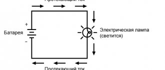
| The current, overcoming the resistance of the conductor, does work. The result of this work is the release of heat. The greater the amount of this heat, the faster the conductor heats up. |
Accordingly, the longer the current flows through the conductor, the greater the resistance of the conductor, the greater the current flows through the conductor, the faster and more it heats up. This is how the Joule-Lenz law characterizes the heating of conductors by electric current.
Note! Electrical conductivity, and therefore the resistance of a conductor, directly depends on its temperature. The higher it is, the greater the resistance of the conductor. Therefore, an avalanche-like process results. The conductor heats up, its resistance increases, and it heats up even more. In this regard, the process of removing heat from the conductor should be given the closest attention.
Heat removal from the conductor and heating stages
In connection with the above property, heating of the conductors must be combated. This is achieved by choosing the optimal wire cross-section, as well as material. That is, the cross-section of the wire must correspond to the maximum permissible current that can flow in it, and also normally withstand short-term overloads.
- In order to calculate all this correctly, we must know not only how the Joule-Lenz law calculates the heating of conductors by electric current, but also how to calculate the heat transfer by a conductor. After all, our conductor is not in a vacuum, and gives off heat to the environment.
Conductor area
- Let's immediately determine what parameters affect the heat transfer of the conductor. First of all, this is the cross-section of the conductor, because it is quite logical that the larger the area of the conductor in contact with the surrounding air, the faster it releases it.
Heat transfer of various materials
- The next important criterion is the so-called heat transfer coefficient of the material from which the conductor is made. Or, as this parameter is also called, the thermal conductivity of the material. After all, it’s no secret that materials have different thermal conductivities.
- Well, the last parameter is the difference between the ambient temperature and the conductor material. After all, as the instructions say: the greater this difference, the faster the material gives off heat.
Steady state temperature
- Based on all these parameters that affect heat transfer, it can be assumed that for any conductor and any current there is a so-called steady-state temperature. That is, the temperature at which there is equality of energy received from the flow of current and heat removed.
Operating temperature of PVC insulated conductor
- This temperature is called steady state. And it must be within the operating temperature of the wire. The operating temperature of the wire is usually limited by the type of insulation used.
For example, for PVC insulation it should not exceed 70⁰C, and various materials impregnated with varnish can withstand temperatures up to 120⁰C and higher.
Thermal effect of current in solids
This is the very first and most obvious effect of current for us.
The thermal effect of current is manifested in the fact that the medium in which it flows heats up.
For example, we use this action in such everyday appliances as an iron, electric kettle, and coffee maker. In conventional incandescent lamps, the thermal effect of current is also observed (Figure 1).
Figure 1. Thermal effect of current in an incandescent lamp
Such lamps contain a thin tungsten wire, which, when current flows through it, heats up so much that it becomes white-hot. If we raise our hand to such a lamp, we will feel warmth. This is the visual thermal effect of current.
Of course, there is also the fact that this spiral not only gives heat, but also glows. We will talk about the luminous effect of current a little lower.
How can the thermal effect of current be observed experimentally? Let's carry out this experiment to make sure that there is a thermal effect of the current.
Let's connect an iron or nickel wire to the current source, as shown in Figure 2.
Figure 2. Thermal effect of current
After the key is closed, current will appear in the circuit. The wire will become noticeably hot. At the same time, it will lengthen and sag a little. Note that before current was passed through it, it was tightly stretched (in the figure, the original position is indicated by a dotted line).
Types of Electric Shock
Depending on the outcome of the electric shock, there are 5 types:
- convulsive muscle contractions, the person is conscious;
- convulsive muscle contractions, a person is unconscious, breathing and heart function are present;
- lack of breathing with impaired heart function;
- electric shock, severe respiratory distress, dysfunction of the circulatory and nervous systems, the onset of deep depression which can last from several tens of minutes to several days and ultimately either complete recovery or biological death occurs;
- clinical death, no breathing, cardiac arrest. It is also called imaginary death, lasts 6-8 minutes, and is a transitional state from life to death. After the specified time, if resuscitation measures are not carried out, biological death occurs.
Also, the path along which the current passes through the body is also of great importance. with what parts of the body does a person touch the conductive part? Most often, people are “connected” to an electrical circuit in such a way that the current passes through loops: “arm-legs”, “arm-arm”, “leg-leg”, “arm-head”, “legs-head”.
The most dangerous are transmission loops in which the current passes through the most important vital organs: the heart, brain, spinal cord, which also have the least electrical resistance in the body and, accordingly, pass through a greater amount of current. This suggests the obvious conclusions that the most dangerous loops are “arm-crawfish” and the paths passing through the head, and the path “leg-leg” is the least dangerous, but nevertheless this is not so, since in this case stepping tension arises, the legs are paralyzed - the person turns out to be in a supine state and electric shock is caused to the entire body.
There are two options for connecting the body to an electrical circuit:
- biphasic - a person simultaneously touches two phases with parts of the body (Figure 2),
- single-phase – touching the phase and zero point (Fig. 3).
Figure 2 - Scheme of two-phase connection of a person to an electrical network
Where, a is a network with an isolated neutral; b – network with solidly grounded neutral.
A two-phase connection is the most dangerous, since in this option the current depends only on the voltage and human resistance (formula 1) and will have a maximum value than with a single-phase connection (see Figure 3).
Figure 3 - Scheme of single-phase connection of a person to the electrical network (a-b)
Figure 3 - Scheme of single-phase connection of a person to the electrical network (c)
- a – network with isolated neutral;
- b – network with solidly grounded neutral.
- c – network with grounded neutral
In option a in Figure 3, to the human resistance - Rch, the shoe resistance Rob is added, Rp - the floor resistance, the phase insulation resistance - Riz. The formula for current strength will take the following form (formula - 2).
Formula 2 - The strength of the current passing through a person during a single-phase connection with an insulated neutral.
Where:
- Uph – phase voltage, V;
- Rh – human resistance (assumed equal to 1000 Ohms.
When calculating, the least resistance is taken (in case of severe intoxication, with wet or damaged skin);
- Rob – shoe resistance;
- Rп – floor resistance;
- Riz – insulation resistance.
Taking into account that the resistance of the floor-shoes-insulation have orders of magnitude greater values than the resistance of a person, then the current flowing through a person with this option is much weaker and less dangerous than with a 2-phase connection.
In emergency mode (see Figure 3b), when one of the phases short-circuits to the housing or goes into the ground, or a contact occurs in a place with damaged insulation, a person may find himself under full line voltage, the current passing through the body in this case is calculated using formula 3:
Formula 3 – The strength of the current passing through a person during a single-phase connection in emergency mode.
The current value when a person is single-phase connected to a network with a grounded neutral is calculated using formula 4.
Formula 4 - The strength of the current passing through a person during a single-phase connection with a grounded neutral.
Return to content
Thermal effect of current in liquids and gases
The wire in the experiment above was a solid body. Will the thermal effect of current manifest itself in liquids or gases? Will!
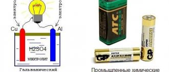
To do this, we will conduct the following experiment. Let's take a vessel with ordinary water and lower two metal plates into it (Figure 3). Let's connect them using wires to a current source. Now these plates will be electrodes .
Place a thermometer in the water and record the temperature. We close the key and an electric current flows through the circuit.
Figure 3. Thermal effect of current in liquid
After 10-15 seconds, you will already see that the thermometer has crawled up. The water temperature began to increase.
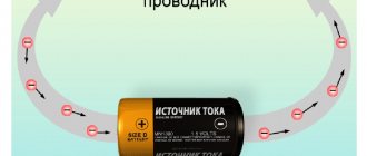
How can this be explained? An electric field causes electrons to move in a certain direction. Their speed increases. This means that their kinetic energy ($E_к = \frac{m \upsilon^2}{2}$) also increases.
During their movement, these electrons will inevitably collide with other particles of matter (in our case, water). When they collide, they will transfer part of their energy to these particles . This means that when current passes through water, its particles receive some additional energy. The total internal energy of water increases. Do you know that this is exactly what leads to an increase in temperature .
We will not perform an experiment confirming the thermal effect of current in air, due to its great complexity. In general, there are very few phenomena where the thermal effect of current in the air is manifested. But, for example, lightning is a clear natural phenomenon, where the thermal effect of the current is also noticeable.
Using the thermal effect of electricity
The thermal effect of electric current is widely used, primarily in heating devices.
Another important use of thermal action is in fuses. If it is necessary to disconnect the electrical circuit when the permissible current is exceeded, then a fuse can be included in the circuit.
Rice. 3. Fuse device.
This is a small flask made of non-flammable material, inside of which there is a fusible wire or tape, the resistance of which is calculated so that when the maximum current is exceeded, it will melt, thereby breaking the electrical circuit.
Chemical effect of current in liquids
How can one experimentally observe the chemical effect of current? Let's return to the previous experiment and take a closer look at the electrodes lowered into water (Figure 4).
Figure 4. Chemical effect of current in water
We will see that even in ordinary water small gas bubbles form around the electrodes. They cannot arise on their own. This means that some kind of chemical reaction is taking place.
Note that we are not talking about boiling here, where we previously observed bubbles forming. The electrodes themselves are barely warm; we can easily touch them with our hands. The temperature of the water is also far from its boiling point. It turns out that the presence of these bubbles is the result of chemical reactions occurring in water when an electric current is passed through it .
Let's conduct another experiment that will more clearly demonstrate to us the chemical effect of current.
Let's replace the water in the vessel from the previous experiment with a solution of copper sulfate $CuSO_4$. It has a blue-greenish color. We will replace metal electrodes with carbon ones (Figure 5).
Figure 5. Chemical effect of current in a solution of copper sulfate
Let's close the key. Current will flow through the circuit. Now let's take a close look at the electrode connected to the negative pole of the current source. A reddish coating has formed on it .
What is this? Where did he come from? This is pure copper $Cu$ . Under the influence of current, it was released from the complex compound and deposited on the negative electrode.
The chemical effect of current is manifested in the fact that when it passes through solutions of salts, acids, and alkalis, a pure substance is released on the electrodes.
This effect of current is actively used in practice in electrometallurgy to obtain pure metals without any impurities (Figure 6).
Figure 6. Detailed illustration of the chemical action of current
This technique is used to apply a thin layer of nickel, silver, and gold to the surface of various objects. This gives the items a beautiful aesthetic appearance and protects them from premature rusting.
Calculation formula and its elements
The essence of the phenomenon is clear from the general definition mentioned above. Moving electrons interact with ions of the conductor substance to convert mechanical energy into heat. Increasing the current increases the intensity of the process.
A good example is electrolysis. When the plates connected to the battery are lowered into the solution, positively charged ions and electrons move in opposite directions. A sufficiently high current provokes the movement of impurities with subsequent deposition on the surface of the electrodes. At the same time, the liquid is heated.
When a copper conductor is connected to a source, there are no chemical reactions. If we exclude mechanical influences (electromagnetic induction, movement of ions in solution), all the work of the current in the corresponding circuit will be aimed only at increasing the internal energy of the substance.
The effect of electric current when connected to a liquid and metal conductor
Therefore, in the second example, work (A) can be taken to be equal to the increase in energy potential, which is expressed by the corresponding amount of heat (Q). Basic formula:
A = Q = U * I *t,
Where:
- U – voltage;
- I – current;
- t – time.
For convenience of calculations, you can use other equivalents based on the formulas of Ohm’s law:
- U = I * R;
- R – electrical resistance of the conductor;
- this means Q = I2 * R * t.
Chemical effect of current in solids and gases
In solids, atoms, molecules or ions are tightly bound together. They are located at the nodes of the crystal lattice and are capable of oscillations. The effect of the current is usually not enough to tear them out of their positions. Therefore, they say that usually the chemical effect of current is not observed in solids.
In gases, it is possible to observe such an effect. Remember an electrophore machine, where a spark jumps between the electrodes.
After passing electric sparks through the air, a characteristic odor arises. ozone was discovered (Figure 7). It consists of three oxygen molecules and has strong oxidizing properties. This allows it to be widely used as a disinfectant.
Figure 7. Ozone molecule
Practical significance
Reduced energy loss
When transmitting electricity, the thermal effect of current in wires is undesirable, since it leads to energy losses. The supply wires and the load are connected in series, which means that the current in the network I{\displaystyle I} on the wires and the load is the same. The load power and wire resistance should not depend on the choice of source voltage. The power released on the wires and on the load is determined by the following formulas
Qw=Rw⋅I2,{\displaystyle Q_{w}=R_{w}\cdot I^{2},} Qc=Uc⋅I.{\displaystyle Q_{c}=U_{c}\cdot I.}
Whence it follows that Qw=Rw⋅Qc2Uc2{\displaystyle Q_{w}=R_{w}\cdot Q_{c}^{2}/U_{c}^{2}}. Since in each specific case the load power and wire resistance remain unchanged and the expression Rw⋅Qc2{\displaystyle R_{w}\cdot Q_{c}^{2}} is a constant, the heat generated on the wire is inversely proportional to the square of the voltage on the consumer. By increasing the voltage, we reduce heat loss in the wires. This, however, reduces the electrical safety of power lines.
Choosing wires for circuits
The heat generated by a current-carrying conductor is released to one degree or another into the environment. If the current strength in the selected conductor exceeds a certain maximum permissible value, such strong heating is possible that the conductor can cause a fire in objects near it or melt itself. As a rule, when choosing wires intended for assembling electrical circuits, it is enough to follow the accepted regulatory documents that regulate the choice of conductor cross-section.
Electric heating devices
If the current strength is the same throughout the entire electrical circuit, then in any selected section the more heat will be generated, the higher the resistance of this section.
By deliberately increasing the resistance of a section of a circuit, localized heat generation can be achieved in that section. Electric heating devices operate on this principle.
.
They use a heating element
- a conductor with high resistance. Increasing the resistance is achieved (jointly or separately) by choosing an alloy with high resistivity (for example, nichrome, constantan), increasing the length of the conductor and reducing its cross-section. The lead wires have a generally low resistance and therefore their heating is usually unnoticeable.
Fuses
Main article: Electric fuse
To protect electrical circuits from the flow of excessively high currents, a piece of conductor with special characteristics is used. This is a conductor with a relatively small cross-section and made of such an alloy that, at permissible currents, heating the conductor does not overheat it, but at excessively high currents, the overheating of the conductor is so significant that the conductor melts and opens the circuit.
Magnetic effect of current
Let's start right away with the experiment. Let's take a copper wire covered with insulating material. Let's wrap it around a nail. We connect the ends of it (the wire) to a current source and a key (Figure 8).
Figure 8. Magnetic effect of current using the example of a nail and copper wire
Let's close the circuit. Let's bring the nail to a pile of small metal objects, for example, other small nails.
What will we see? The nail will attract other iron objects to itself - it has become a magnet. If we open the circuit, the nail will demagnetize.
The most interesting thing is that the magnetic effect of current is universal. It manifests itself in solids, liquids, and gases. In addition, if you force a charge to move directionally in a highly rarefied space (this phenomenon is called current in a vacuum ), then its magnetic effect can be observed here too.
Nature and consequences of human exposure
The nature and consequences of the dangerous and harmful effects of electric current on a person depend on many factors:
- on the magnitude and type (alternating or direct) of the flowing current;
- the duration of its impact (the longer the duration of the current on a person, the more severe the consequences);
- flow paths;
- on the physical and psychological state of a person;
- depending on the state of the external environment, for example, high humidity, the effect of electricity on the body will be stronger.
The magnitude and type of current flow is the main factor on which the outcome of its effect on the human (or animal) body depends.
According to the degree of impact on a person, the current is divided into three threshold values:
- A person begins to feel the impact of alternating current passing through him at a value of 0.6 mA, direct starting from 5-7 mA. These values are called threshold sensible currents.
- The next threshold is the threshold of non-releasing (holding) current. Its value for alternating current is ≥10 mA, for direct current ≥50 mA.
- The third threshold value is fibrillation current. This value of alternating current is 100 mA, and constant current is 300 mA; with a duration of exposure to such current of 0.5 seconds, cardiac arrest or fibrillation may occur.
Table 1 shows the various reactions of the human body to electric current depending on its strength and type.
Table 1 - the effect of electric current on a person depending on the threshold values and type (direct and alternating)
| Current strength, mA | Nature of impact | |
| D.C | AC 50 Hz | |
| 0,6—1,6 | Not felt | The beginning of the sensation is mild itching, tingling of the skin under the electrodes |
| 2—4 | Not felt | The sensation of current spreads to the wrist, slightly cramps the hand |
| 5—7 | The beginning of the sensation. The impression of skin heating under the electrode | The pain intensifies throughout the entire hand and is accompanied by cramps. Hands, as a rule, can be removed from the electrodes |
| 8—10 | Increased feeling of heating | Severe pain and cramps in the entire arm, including the forearm. It is difficult to take your hands off the electrodes |
| 10—15 | Increased feeling of heating | Barely bearable pain in the whole arm. It is impossible to take your hands off the electrodes. |
| 20—25 | An even greater sensation of skin heating. | The hands are instantly paralyzed; it is impossible to tear yourself away from the electrodes. Severe pain, difficulty breathing |
| 25—50 | Feeling of intense heating, pain and cramps in the hands. When you remove your hands from the electrodes, barely bearable pain occurs as a result of convulsive muscle contractions | Very severe pain in the arms and chest. Breathing is extremely difficult. With prolonged current, respiratory paralysis or weakening of heart activity with loss of consciousness may occur |
| 50—80 | A feeling of very strong superficial and internal heating, severe pain in the entire arm and in the chest area. Difficulty breathing. It is impossible to take your hands off the electrodes due to severe pain when contact is broken | Breathing becomes paralyzed within a few seconds, and heart function is disrupted. With prolonged current flow, cardiac fibrillation may occur. |
| 100 | Respiratory paralysis due to prolonged current flow | Heart fibrillation after 2-3 s; after a few more seconds - cardiac paralysis |
| 300 | Heart fibrillation after 2-3 s; after a few more seconds - respiratory paralysis | Same action in less time |
| more than 5000 | Breathing is paralyzed immediately - within a split second. Cardiac fibrillation, as a rule, does not occur; Temporary cardiac arrest is possible during the current flow. If current flows for a long time (several seconds), severe burns and tissue destruction | |
As can be seen from Table 1, alternating current is more dangerous than direct current. However, even a small direct current below the threshold of sensation gives strong shocks that can cause muscle cramps. And at a voltage value above 500 V, direct current is already more dangerous since it has great “stickiness” and it is almost impossible to free yourself from it.
At the same time, although alternating current is considered more dangerous for humans, this mainly concerns the frequency of 50 Hz. With an increase in frequency, even taking into account that the body’s resistance drops and the current flowing through it increases, the danger of electric shock decreases and completely disappears at a frequency of 450 - 500 GHz, because at a high frequency, the so-called “skin” effect occurs - the current flows along the surface of the body, the skin, and cannot affect a person. But we practically never encounter currents of this frequency either in everyday life or in production, in contrast to the 50 Hz alternating voltage, which is the standard in Russian electrical networks.
Return to content
Galvanometer. Magnetic effect of current in its device
First, let's look at how a current-carrying conductor and a magnet will interact.
To do this, we will build the following structure. We attach a thin copper wire to a small frame with several turns. The frame itself will be suspended on threads so that we can observe any of its movements.
The wire that wraps around the frame is connected to the poles of the current source. Let's close the key. The frame will remain motionless (Figure 9).
Figure 9. Frame with current is motionless
Now let's take a magnet. Let's position it so that the current-carrying frame is between its poles (Figure 10).
Figure 10. A current-carrying frame placed between the poles of a magnet rotates
Now the frame has started to turn! It is this phenomenon of interaction of such a peculiar coil with current and a magnet that underlies the design of a special device - a galvanometer (Figure 11).
Figure 11. Galvanometer and its symbols for electrical circuit diagrams
A galvanometer is a device that can be used to determine the presence of current in a conductor.
Figure 11a shows the appearance of this device. Figure 11, b shows the symbol with which a galvanometer is indicated on an electrical circuit diagram.
The galvanometer needle is connected to a coil inside the instrument itself. By coil we mean a wire wound on a dielectric frame.
This coil inside the device is in a magnetic field. When current flows through the coil, the needle deflects. So, when connecting a galvanometer to a circuit, we can judge the presence of electric current in it.
Selection of conductors
As you can understand from everything written above, conductors should be selected based on heating conditions. So that at a certain current their temperature does not exceed the maximum permissible. You can do this yourself, thanks to the tables in the PUE. But this issue also needs to be sorted out first.
- The PUE contains tables by which you can select conductors based on heating, economic current density, installation method and other parameters. But first, we must know exactly the installation and operating conditions of the wire. Let's look at why this is needed.
Permissible overloads for paper-insulated cables
- But first, let's deal with the current. It's no secret that the current in the conductor will change over time. And which of them should be considered as the result for choosing a conductor cross-section is not clear. This question is answered by clause 1.3.2 of the PUE, which states that for selection, the average current should be used for half an hour, the most loaded during the day.
The photo shows the temperature correction coefficients
- Now let's decide on the temperature. In different installation locations it can differ quite significantly from the operating temperature. This should be taken into account. Therefore, in Table. 1.3.3 PUE provides correction factors for various cable and wire products, if the temperature at which the cable will operate differs from the operating temperature.
- The choice of conductors based on heating and current density necessarily takes into account the method of laying the conductor. This can be a single installation through the air, or it can be installed in the ground or in pipes. Agree, the heat dissipation of such conductors will be significantly different. And this is definitely worth taking into account.
- The number of conductor strands should also be taken into account. Either we have one core cooling, or three that are in contact.
Note! In table 1.3.12 PUE there is a separate correction factor when installing conductors in bundles. After all, if we have several conductors laid nearby at once, then they may well heat each other and cool down noticeably worse. And this should also be taken into account.
Selecting the cross-section of conductors in rubber and PVC insulation
- As a result, we will be able to use tables 1.3.4. – 1.3.11 PUE, which prescribe what cross-sectional conductors to use for different currents, and when using conductors with different types of insulation.
Note! If you are choosing a conductor for a living space, you should immediately exclude wires and cables made of aluminum. Indeed, according to the new PUE standards of 2001, such material is prohibited in electrical wiring of residential buildings.
Economic Current Density Table
- But these tables can be used for not the most powerful lines. When calculating intersystem high-voltage lines with a voltage of 330 kV and above, you cannot rely on these tables. In this case, use Table 1.3.36 of the PUE, which allows you to select the cross-section of conductors based on the economic current density.
From this video you will learn about the requirements for conductors.
Light effect of current
Older incandescent bulbs emit more light due to the high temperature of the tungsten wire in their device. Therefore, in their work there is a greater thermal effect of the current.
But in the second half of the 20th century, new light sources were invented. Here the temperature of the conductor itself no longer plays a role, but more complex processes occur.
You probably already guessed that we are talking about LED lamps (Figure 12). At the moment, these are the lamps we most often use in everyday life.
Figure 12. LED lamps
The luminous effect is manifested in the appearance of light radiation during the passage of current.
Electric arc
An electric arc is a fairly efficient converter of electrical energy. It is used in welding metal structures and also serves as a powerful light source.
The device is based on the following. Take two carbon rods, connect the wires and attach them in insulating holders. After this, the rods are connected to a current source, which gives a low voltage, but is designed for high current. Connect the rheostat. It is prohibited to include coals in the city network, as this may cause a fire. If you touch one coal to another, you will notice how hot they become. It is better not to look at this flame, because it is harmful to your eyesight. An electric arc is used in furnaces for melting metal, as well as in such powerful lighting devices as spotlights, film projectors, etc.
Tasks
Task No. 1
Consider Figure 8, which shows a setup for observing the magnetic effect of current.
What is each part of this installation? Tell us how the experience goes. At the top of the figure is a current source . wire is connected to its positive terminal . Next, this wire is wound on an ordinary iron nail . The wire runs from the nail to the key , and from the key to the current source (its negative pole).
In the picture the key is closed. Electric current flows in the circuit. An iron nail is instantly magnetized - it becomes a magnet . It attracts other small iron objects to itself.
As soon as we open the circuit, current will stop flowing through the wires. The iron nail will become demagnetized . All small objects previously magnetized to it will disappear.
Task No. 2
Using Figures 9 and 10, tell how the interaction of a frame with current and a magnet is observed experimentally.
Let's assemble an electrical circuit from a current source, a key, connecting wires and a frame with a winding of thin wire connected to the wires . We will hang the frame on threads so that we can track any of its movements.
Let's close the key. Current will flow through the circuit. The frame will remain motionless .
Now let's take a magnet . Let's place it so that the frame is between its poles. Let's close the circuit again. Now the frame began to move - it began to turn .
the magnetic effect of electric current manifests itself . It is this phenomenon that is used in the galvanometer device.
Joule-Lenz law
Electricity is an integral feature of our era. Absolutely everything around is tied to it. Any modern person, even without technical education, knows that electric current flowing through wires can, in some cases, heat them, often to very high temperatures. It would seem that this is known to everyone and is not worth mentioning. However, how to explain this phenomenon? Why and how does the conductor heat up?
Lenz's experiments
Let's fast forward to the 19th century, the era of accumulation of knowledge and preparation for the technological leap of the 20th century. An era when all over the world various scientists and simply self-taught inventors discover something new almost every day, often spending a huge amount of time on research and, at the same time, not presenting the final result.
One of these people, the Russian scientist Emilius Christianovich Lenz, was fascinated by electricity, at the then primitive level, trying to calculate electrical circuits. In 1832, Emilius Lenz was “stuck” with calculations, since the parameters of his simulated circuit “energy source - conductor - energy consumer” varied greatly from experiment to experiment. In the winter of 1832-1833, the scientist discovered that the cause of the instability was a piece of platinum wire that he brought from the cold. When heating or cooling a conductor, Lenz also noticed that there was a certain relationship between the current strength, electrical resistance and temperature of the conductor.
Using the thermal effect of electricity
The thermal effect of electric current is widely used, primarily in heating devices.
Another important use of thermal action is in fuses. If it is necessary to disconnect the electrical circuit when the permissible current is exceeded, then a fuse can be included in the circuit.
Rice. 3. Fuse device.
This is a small flask made of non-flammable material, inside of which there is a fusible wire or tape, the resistance of which is calculated so that when the maximum current is exceeded, it will melt, thereby breaking the electrical circuit.
Pros and cons of electric heating
- Pros. Heating of conductors with electric current finds its application in various useful appliances and devices: electric stoves, kettles, coffee makers, boilers, hair dryers, irons, heaters.
- Minuses. Very often, electronics engineers have to deal with this effect in order, for example, to ensure the functionality of electronic boards, which are stuffed with a huge number of electronic parts, microcircuits, etc. All these elements heat up in accordance with the Joule-Lenz law. And if measures are not taken for forced cooling using metal radiators or fans (coolers), then the boards will quickly fail from overheating.
Rice. 2. Household heating appliances: kettle, iron, hair dryer, electric stove.
Often, to quickly connect wires, many people use the “twisting” method. This leads to a significant increase in resistance, and therefore, the “twisted” area will heat up more than the rest of the wiring. Therefore, twisting of wires often causes fires in houses and apartments. To improve contact, you need to solder this place well.