DC Power Measurement
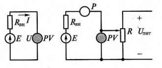
Due to the lack of reactive and active components in DC circuits, a wattmeter is very rarely used to measure power. As a rule, the amount of energy consumed or supplied is measured by an indirect method; the current I in the circuit is measured using a series-connected ammeter, and the load voltage U is measured using a parallel-connected voltmeter. Then, using the simple formula P=UI, the power value is obtained.
To reduce the measurement error due to the influence of internal resistances of devices, devices can be connected using various circuits, namely, with a relatively low load resistance R, the following connection circuit is used:
And for a large value of R, such a scheme:
Measuring power and energy in electrical circuits
Power measurement. In DC circuits, power is measured with an electro- or ferrodynamic wattmeter. Power can also be calculated by multiplying the current and voltage values measured with an ammeter and a voltmeter.
In single-phase current circuits, power measurement can be carried out with an electrodynamic, ferrodynamic or induction wattmeter. Wattmeter 4 (Fig. 336) has two coils: current 2, which is connected to the circuit in series, and voltage 3, which is connected to the circuit in parallel.
The wattmeter is a device that requires correct polarity when turned on, so its generator terminals (the clamps to which the conductors coming from source 1 are connected) are designated with asterisks.
Rice. 336. Circuit for measuring power
To expand the measurement limits of wattmeters, their current coils are connected to the circuit using shunts or measuring current transformers, and the voltage coils are connected through additional resistors or measuring voltage transformers.
Electrical energy measurement. Method of measurement. To account for electrical energy received by consumers or supplied by current sources, electrical energy meters are used. The principle of operation of an electric energy meter is similar to a wattmeter. However, unlike wattmeters, instead of a spiral spring that creates a counteracting torque, meters are equipped with a device similar to an electromagnetic damper that creates a braking force proportional to the rotational speed of the moving system. Therefore, when the device is connected to an electrical circuit, the resulting torque will not cause the moving system to deflect at a certain angle, but rather cause it to rotate at a certain frequency.
The number of revolutions of the moving part of the device will be proportional to the product of the power of the electric current and the time during which it operates, i.e., the amount of electrical energy passing through the device. The number of revolutions of the counter is fixed by a counting mechanism. The gear ratio of this mechanism is chosen so that according to the meter readings it is possible to count not the revolutions, but directly the electrical energy in kilowatt-hours.
The most widespread are ferrodynamic and induction meters; the former are used in direct current circuits, the latter in alternating current circuits. Electric energy meters are included in electrical circuits of direct and alternating current in the same way as wattmeters.
Ferrodynamic counter
(Fig. 337) set on e. p.s. direct current. It has two coils: a stationary coil 4 and a moving coil 6. The stationary current coil 4 is divided into two parts, which enclose a ferromagnetic core 5 (usually made of permalloy). The latter allows you to create a strong magnetic field and significant torque in the device, ensuring normal operation of the meter under conditions of shaking and vibration. The use of permalloy helps to reduce the error of the counting mechanism 2 from the hysteresis of the magnetic system (it has a very narrow hysteresis loop).
To reduce the influence of external magnetic fields on the meter readings, the magnetic fluxes of individual parts of the current coil have mutually opposite directions (astatic system). In this case, the external field, weakening the flux of one part, accordingly enhances the flux of the other part and generally has a small effect on the resulting torque created by the device. The moving coil 6 of the meter (voltage coil) is located on an armature made in the form of a disk of insulating material or in the form of an aluminum bowl. The coil consists of separate sections connected to collector plates 7 (these connections are not shown in Fig. 337), along which brushes made of thin silver plates slide.
A ferrodynamic meter operates fundamentally like a DC motor, the armature winding of which is connected in parallel, and the field winding is connected in series with the electricity consumer. The armature rotates in the air gap between the poles of the core. The braking torque is created as a result of the interaction of the flux of the permanent magnet 1 with eddy currents arising in the aluminum disk 3 during its rotation.
To compensate for the influence of the friction torque and thereby reduce the instrument error, a compensation coil is installed in ferrodynamic meters or a permalloy petal, which has high magnetic permeability at low field strength, is placed in the magnetic field of a stationary (current) coil. At light loads, this lobe enhances the magnetic flux of the current coil, which leads to an increase in torque and compensation for friction. As the load increases, the induction of the magnetic field of the coil increases, the lobe becomes saturated and its compensating effect ceases to increase.
When the meter operates on e. p.s. strong shocks and impacts are possible, during which the brushes can bounce off the commutator plates. In this case, sparking will occur under the brushes. To prevent it, capacitor C and resistor R1 are connected between the brushes. Compensation for temperature errors is carried out using a thermistor Rt (a semiconductor device whose resistance depends on temperature). It is connected together with an additional resistor R2 in parallel with the moving coil. To reduce the effect of shaking and vibration on the operation of the meters, they are installed on e. p.s. on rubber-metal shock absorbers.
Induction counter
has two electromagnets (Fig. 338, a), between which an aluminum disk 7 is located. The torque in the device is created as a result of the interaction of alternating magnetic fluxes F1 and F2, created by the coils of electromagnets, with the eddy currents Iв1 and Iв2, induced by them in the aluminum disk ( the same as in a conventional induction measuring mechanism, see § 99).
In an induction meter, the torque M must be proportional to the power P=UIcos?. To do this, coil 6 of one of the electromagnets (current) is connected in series with load 5, and coil 2 of the other (voltage coil) is connected in parallel with the load. In this case, the magnetic flux F1 will be proportional to the current I in the load circuit, and the flux F2 will be proportional to the voltage U applied to the load. To ensure the required phase shift angle? Between the flows Ф1 and Ф2 (so that sin? = cos?) a magnetic shunt 3 is provided in the electromagnet of the voltage coil, through which part of the flow Ф2 is closed
Rice. 337. Ferrodynamic electric energy meter
Rice. 338. Induction meter for electrical energy
in addition to disk 7. The phase shift angle between flows F1 and F2 is precisely controlled by changing the position of the metal screen 1 located in the path of the flow branching through the magnetic shunt 3.
The braking torque is created in the same way as in a ferrodynamic counter. Compensation for the friction torque is carried out by creating a slight asymmetry in the magnetic circuit of one of the electromagnets using a steel screw.
To prevent rotation of the armature when there is no load under the influence of the force created by the friction-compensating device, a steel brake hook is attached to the meter axis. This hook is attracted to the brake magnet 4, thereby preventing the moving system from rotating without a load.
When the meter is operating under load, the brake hook has virtually no effect on its readings.
In order for the counter disk to rotate in the required direction, it is necessary to follow a certain order of connecting the wires to its terminals. The load terminals of the device, to which the wires coming from the consumer are connected, are designated by the letters I (Fig. 338, b), the generator terminals, to which the wires from the current source or from the alternating current network are connected, by the letters G.
Power measurement in single-phase AC circuits
The main difference between alternating current circuits and direct current networks, perhaps, is that in alternating voltage there are several powers - total, active and reactive. Total is often measured using the same indirect method using an ammeter and voltmeter and its value is equal to S = UI.
Active P=UIcosφ and reactive Q=UIsinφ are measured using a direct method, using a wattmeter. To measure, a wattmeter is connected to the circuit according to the following diagram:
Where the current winding must be connected in series with the load Rн, and, accordingly, the voltage winding in parallel with the load.
Reactive power is not measured in single-phase networks. Such experiments are often carried out only in laboratories where wattmeters are switched on according to special circuits.
Connecting a Wattmeter
Wattmeters have four terminals (2 inputs, 2 outputs) for connection. Two of them are used when assembling a serial (current) circuit - it is connected first, and two - for a parallel (voltage circuit).
The beginning of the voltage circuit (input) is connected to the beginning of the current circuit (connect the terminals with a jumper), connected to one terminal of the network. The end of the voltage circuit (output) is connected to another terminal of the network.
Let's consider several wattmeters of different designs and different manufacturers:
Multifunctional digital wattmeter CM3010 accuracy class 0.1
Designed to measure active power, current, voltage and frequency in DC circuits and single-phase AC circuits; for testing wattmeters, ammeters, voltmeters of class 0.3 and below, frequency meters of class 0.01 and below.
Current measurement limits Iп:
- on direct and alternating current: 0.002-0.005-0.01-0.02-0.05-0.1-0.2-0.5-1-2-5-10 A.
Voltage measurement limits Up:
- DC: 1-3-7.5-15-30-75-150-300-450-700-1000 V.
- alternating current: 1-3-7.5-15-30-75-150-300-450-700 V.
Power measurement limits respectively Up* Iп
Frequency measurement limits are from 40 to 5000Hz.
Basic error:
- reduced error in measuring current, voltage and power at direct current ±0.1%;
- reduced error in measuring current and voltage on alternating current in the frequency range from 40 to 1500 Hz ±0.1%;
- reduced error in measuring power on alternating current in the frequency range from 40 to 1000 Hz ±0.1%;
- relative frequency measurement error in the frequency range from 40 to 5000 Hz ±0.003%;
Overall dimensions 225x100x205 mm. Weight no more than 1 kg. Power consumption no more than 5W.
Multifunctional wattmeters SM3010 are produced according to TU 4221-047-16851585-2014, comply with the requirements of TR TS 004/2011, TR TS 020/2011.
Manufactured by ZIP-Nauchpribor.
Measuring devices TsP8506-120 (hereinafter referred to as devices).
Designed to measure active, reactive, active and reactive three-phase three-wire AC circuits, display the current value of the measured power on a digital indicator and convert it into an analog output signal (hereinafter referred to as the output signal).
The measured values are displayed digitally on built-in indicators. The measured values are displayed on digital indicators in units of the measured value supplied directly to the input of the device, or in units of the measured value supplied to the input of current and voltage transformers, taking into account transformation ratios, in watts, kilowatts, megawatts, vars, kilovars, megavars. Digital indicators have four significant digits.
Purpose of CPU8506-120:
- for measuring active and reactive power in three-phase three-wire electrical circuits of alternating current with a frequency of 45 to 55 Hz
Brief technical specifications of CPU8506-120 (Wattmeter)
Panel digital three-phase varmeter:
- Power factor: for a wattmeter cos φ=1, for a varmeter sin φ=1
- Overall dimensions: 120x120x150 mm
- Sign height: 20 mm
- Maximum display range: 9999
- Accuracy class: 0.5
- Conversion time: no more than 0.5s
- Operating temperature: +5 ... +40 degrees C (O4.1), -40 ... +50 degrees C (UHL3.1)
- Front panel protection degree: IP40
- Power consumption: 5VA
- Weight: no more than 1.2 kg
Power measurement in three-phase AC circuits
As in single-phase networks, also in three-phase networks, the total energy of the network can be measured by an indirect method, that is, using a voltmeter and ammeter according to the diagrams shown above. If the load of the three-phase circuit is symmetrical, then the following formula can be applied:
Ul – linear voltage, I – phase current.
If the phase load is not symmetrical, then the power of each phase is summed up:
When measuring active energy in a four-wire circuit using three wattmeters, as shown below:
The total energy consumed from the network will be the sum of the wattmeter readings:
The method of measuring with two wattmeters has also become equally widespread (applicable only for three-wire circuits):
The sum of their readings can be expressed by the following expression:
For a symmetrical load, the same formula applies as for total energy:
Where φ is the shift between current and voltage (phase shift angle).
The reactive component is measured according to the same scheme (see figure c)) and in this case it will be equal to the algebraic difference between the instrument indicators:
If the network is not symmetrical, then to measure the reactive component, two or three wattmeters are used, which are connected according to different circuits.
The process of measuring active and reactive power
Induction or electronic meters measure the active power of an alternating voltage circuit. They are connected using the same circuits as wattmeters. Reactive energy in single-phase consumers is not metered in our country. It is metered in three-phase circuits of large industrial enterprises that consume large volumes of electricity. Active energy meters are marked SA, reactive SR. Electronic electricity meters are also widely used.
How to determine the current strength in a 220V outlet?
instrument.guru > Electricity > How to determine the current strength in a 220V outlet?
Almost any premises, whether residential or industrial, are equipped with sockets for connecting electrical appliances.
For stable and safe operation of electrical appliances, it is necessary to know not only the voltage in the network (standard 220 volts), but also the current strength for which the outlet is designed.
It should be noted that this electrical equipment itself does not have any current strength; it only withstands a certain amount when connecting any household or industrial equipment.
Methods for determining current strength
- The device is an ammeter .
An ammeter is a measuring device that determines the current strength and displays it on an existing scale. To do this, you need to connect a closed circuit in series: a socket, a unit of household appliances, an ammeter and again a socket. Instead of an ammeter, you can use a multimeter - a combination device that includes a voltmeter, ammeter and ohmmeter. The error in current measurements on a specific section of the circuit will depend on the accuracy class of the measuring device. - By calculation method.
To apply the calculation method, you need to know the power value of the connected device.Taking into account that in our country, the main part of the premises is supplied with a standard voltage of 220 volts, the current strength in a 220V outlet can be calculated using the following formula:
I = P / U, where I is current (ampere); P – power of the electrical appliance (watt); U – network voltage (volts).
This method determines how many amperes are in a 220V outlet. For example, using the formula, you can calculate what current is in a 220V outlet when connecting a conventional electric kettle with a power of 2.5 kilowatts or 2500 watts. The resulting value is 11.36 amperes.
Current characteristics
When calculating the amount of current that the outlet supports, it is necessary to clarify the current characteristic. There are two of them: direct current and alternating current.
Variable is most widespread in the field of electricity consumption, since its losses during transmission over long distances are significantly less.
If necessary, conversion is carried out using circuits of consumer devices. Thus, the outlet supports alternating current of 220 volts.
Types of electrical outlets
Equipment used in everyday life has different power characteristics, therefore, the electrical fittings in the premises must be appropriate. Today's household devices are more powerful than older technology.
Just 20 years ago, an outlet limited to 6 amps could be used for all devices. This connector was intended for equipment with a power of up to 1.5 kilowatts or 1500 watts. This is not enough for modern life.
Currently the load limit is:
- 16 amperes for ordinary premises, which guarantees the safe operation of consumers with a power of up to 3.5 kilowatts;
- 25 amperes for apartments or houses where electric stoves with a power of up to 6 kilowatts are installed. Such sockets are called power sockets;
- 32 amperes at increased loads on the network, for example, when connecting several powerful ovens or stoves in production. In this case, a three-phase cable is used, which is designed for 380 volts. Accordingly, the sockets must also be three-phase. This equipment differs in its design. If there is an increased load on the network in a private home, in addition to installing special equipment, reinforced electrical wiring is also required.
The need for automatic power off
A circuit breaker is an important element in the electrical supply system of a room. There are special devices on distribution panels that indicate how many amperes of the maximum allowable current. Typically, 16, 25 or 32 ampere circuit breakers are installed for household purposes.
It is recommended to install its own circuit breaker for each powerful device. For example, an electric stove has a power of 6 kilowatts or 6000 watts, therefore the current will be 27 amperes at a voltage of 220 volts.
In this case, you need a larger circuit breaker, namely 32 amperes.