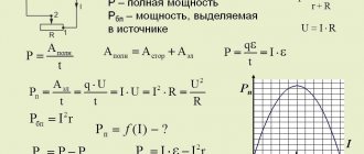
b
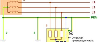
Rice. 1.7.5. TT system of alternating (a) and direct (b) current. The exposed conductive parts of the electrical installation are grounded using grounding that is electrically independent of the neutral grounding conductor: 1 - neutral grounding conductor of the alternating current source; 1-1 — ground electrode of the DC source output; 1-2 - ground electrode of the middle point of the DC source; 2 - open conductive parts; 3 - grounding conductor of open conductive parts of the electrical installation; 4 - power supply
1.7.5. Solidly grounded neutral - the neutral of a transformer or generator connected directly to the grounding device. The output of a single-phase alternating current source or the pole of a direct current source in two-wire networks, as well as the midpoint in three-wire DC networks, can also be solidly grounded.
1.7.6. Isolated neutral - the neutral of a transformer or generator, not connected to a grounding device or connected to it through a high resistance of signaling, measuring, protection and other similar devices.
1.7.7. Conductive part is the part that can conduct electric current.
1.7.8. Current-carrying part is a conductive part of an electrical installation that is under operating voltage during its operation, including the neutral working conductor (but not PEN
- conductor).
1.7.9. An exposed conductive part is a conductive part of an electrical installation that is accessible to touch, not normally energized, but which may become energized if the main insulation is damaged.
1.7.10. Third party conductive part - a conductive part that is not part of the electrical installation.
1.7.11. Direct touch is electrical contact of people or animals with live parts.
1.7.12. Indirect touch is electrical contact of people or animals with exposed conductive parts that become energized when the insulation is damaged.
1.7.13. Protection against direct contact - protection to prevent contact with live parts.
1.7.14. Protection against indirect contact - protection against electric shock when touching exposed conductive parts that become live when the insulation is damaged.
The term insulation failure should be understood as a single insulation failure.
1.7.15. Ground electrode - a conductive part or a set of interconnected conductive parts that are in electrical contact with the ground directly or through an intermediate conductive medium.
1.7.16. An artificial grounding conductor is a grounding conductor specially made for grounding purposes.
1.7.17. Natural grounding - a third-party conductive part that is in electrical contact with the ground directly or through an intermediate conducting medium, used for grounding purposes.
1.7.18. Grounding conductor is a conductor connecting the grounded part (point) to the ground electrode.
1.7.19. Grounding device - a combination of grounding conductors and grounding conductors.
1.7.20. Zero potential zone (relative ground) is a part of the earth located outside the zone of influence of any ground electrode, the electric potential of which is assumed to be zero.
1.7.21. Spreading zone (local ground) is the ground zone between the ground electrode and the zero potential zone.
The term ground used in the chapter should be understood as the ground in the spreading zone.
1.7.22. A ground fault is an accidental electrical contact between live parts and the ground.
1.7.23. The voltage on the grounding device is the voltage that occurs when current flows from the ground electrode into the ground between the point of current input into the ground electrode and the zero potential zone.
1.7.24. Touch voltage is the voltage between two conductive parts or between a conductive part and the ground when simultaneously touched by a person or animal.
Expected touch voltage - the voltage between simultaneously accessible conductive parts when a person or animal does not touch them
1.7.25. Step voltage is the voltage between two points on the surface of the earth, at a distance of 1 m from one another, which is taken to be equal to the length of a person’s step.
1.7.26. The resistance of the grounding device is the ratio of the voltage on the grounding device to the current flowing from the grounding device into the ground.
1.7.27. Equivalent resistivity of earth with a heterogeneous structure is the specific electrical resistance of earth with a homogeneous structure, in which the resistance of the grounding device has the same value as in earth with a heterogeneous structure.
The term resistivity, used in the chapter for earth with a heterogeneous structure, should be understood as equivalent resistivity.
1.7.28. Grounding is an intentional electrical connection of any point in the network, electrical installation or equipment with a grounding device.
1.7.29. Protective grounding is grounding performed for electrical safety purposes.
1.7.30. Working (functional) grounding - grounding of a point or points of live parts of an electrical installation, performed to ensure the operation of the electrical installation (not for electrical safety purposes).
1.7.31. Protective grounding in electrical installations with voltages up to 1 kV is a deliberate connection of open conductive parts with a solidly grounded neutral of a generator or transformer in three-phase current networks, with a solidly grounded output of a single-phase current source, with a grounded source point in direct current networks, performed for electrical safety purposes.
1.7.32. Potential equalization is the electrical connection of conductive parts to achieve equality of their potentials.
Protective potential equalization is potential equalization performed for electrical safety purposes.
The term potential equalization used in the chapter should be understood as protective potential equalization.
1.7.33. Potential equalization is a reduction in the potential difference (step voltage) on the surface of the earth or floor using protective conductors laid in the ground, in the floor or on their surface and connected to a grounding device, or by using special earth coverings.
1.7.34. Protective ( RE
) conductor - a conductor intended for electrical safety purposes.
Protective grounding conductor is a protective conductor designed for protective grounding.
Protective potential equalization conductor - a protective conductor designed for protective potential equalization.
Neutral protective conductor is a protective conductor in electrical installations up to 1 kV, intended for connecting open conductive parts to the solidly grounded neutral of the power source.
1.7.35. Zero working (neutral) conductor ( N
) - a conductor in electrical installations up to 1
kV
, intended for powering electrical receivers and connected to a solidly grounded neutral of a generator or transformer in three-phase current networks, with a solidly grounded output of a single-phase current source, with a solidly grounded source point in DC networks.
1.7.36. Combined zero protective and zero working ( PEN
) conductors - conductors in electrical installations with voltages up to 1
kV
, combining the functions of the zero protective and zero working conductors.
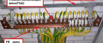
1.7.37. Main grounding bus - a bus that is part of the grounding device of an electrical installation up to 1 kV
and designed for connecting several conductors for the purpose of grounding and potential equalization.
1.7.38. Protective automatic power off - automatic opening of the circuit of one or more phase conductors (and, if required, the neutral working conductor), performed for electrical safety purposes.
The term automatic power off used in this chapter should be understood as protective automatic power off.
1.7.39. Basic insulation is the insulation of live parts, including protection from direct contact.
1.7.40. Additional insulation - independent insulation in electrical installations with voltages up to 1 kV
, performed in addition to the main insulation for protection against indirect contact.
1.7.41. Double insulation - insulation in electrical installations with voltages up to 1 kV
, consisting of main and additional insulation.
1.7.42. Reinforced insulation - insulation in electrical installations with voltages up to 1 kV
, providing a degree of protection against electric shock equivalent to double insulation.
1.7.43. Extra-low (small) voltage ( ELV
) - voltage not exceeding 50
V
AC and 120
V
DC.
1.7.44. Isolation transformer - a transformer whose primary winding is separated from the secondary windings by means of protective electrical separation of circuits.
1.7.45. Safety isolation transformer is an isolation transformer designed to supply circuits with extra-low voltage.
1.7.46. Protective shield is a conductive shield designed to separate an electrical circuit and/or conductors from live parts of other circuits.
1.7.47. Protective electrical separation of circuits - separation of one electrical circuit from other circuits in electrical installations with voltages up to 1 kV
by using:
double insulation;
main insulation and protective screen;
reinforced insulation
1.7.48. Non-conducting (insulating) rooms, zones, sites - rooms, zones, sites in which (in which) protection from indirect contact is provided by high resistance of the floor and walls and in which there are no grounded conductive parts.
Precautions against direct contact
1.7.67. Basic insulation of live parts must cover the live parts and withstand all possible impacts to which it may be subjected during its operation. Removal of insulation should only be possible by destroying it. Paint and varnish coatings are not insulation that protects against electric shock, except in cases specifically specified in the technical specifications for specific products. When performing insulation during installation, it must be tested in accordance with the requirements of Chapter. 1.8.
In cases where basic insulation is provided by an air gap, protection from direct contact with live parts or approaching them at a dangerous distance, including in electrical installations with voltages above 1 kV
, must be carried out by means of shells, fences, barriers or placement out of reach.
1.7.68. Fencing and shells in electrical installations with voltage up to 1 kV
must have a degree of protection of at least
IP 2X
, except in cases where large clearances are necessary for the normal operation of electrical equipment.
Guards and shells must be securely fastened and have sufficient mechanical strength.
Entering the fence or opening the shell should be possible only with the help of a special key or tool or after removing the voltage from live parts. IP 2X must be installed.
, the removal of which should also be possible only with the help of a special key or tool.
1.7.69. Barriers are designed to protect against accidental contact with live parts in electrical installations with voltages up to 1 kV
or approaching them at a dangerous distance in electrical installations with voltages above 1
kV
, but do not exclude deliberate touching and approaching live parts when bypassing the barrier. Removal of barriers does not require the use of a wrench or tool, but they must be secured so that they cannot be removed inadvertently. Barriers must be made of insulating material.
1.7.70. Placement out of reach for protection from direct contact with live parts in electrical installations with voltage up to 1 kV
or approaching them at a dangerous distance in electrical installations with voltages above 1
kV
can be applied if it is impossible to carry out the measures specified in 1.7.68-1.7.69 or their insufficiency.
In this case, the distance between conductive parts accessible to simultaneous touch in electrical installations with voltages up to 1 kV
must be at least 2.5
m.
Within the reach zone there should be no parts that have different potentials and are accessible to simultaneous touch.
In the vertical direction, the reach zone in electrical installations with voltages up to 1 kV
should be 2.5
m
from the surface on which people are located (Fig. 1.7.6).
The indicated dimensions do not take into account the use of auxiliary equipment (for example, tools, ladders, long objects).
1.7.71. Installation of barriers and placement out of reach is only permitted in areas accessible to qualified personnel.
1.7.72. In electrical rooms of electrical installations with voltage up to 1 kV
Protection from direct contact is not required if the following conditions are met simultaneously:
these rooms are clearly marked and can only be accessed with a key;
it is possible to freely exit the premises without a key, even if it is locked from the outside;
The minimum dimensions of service passages correspond to Ch. 4.1.
Rice. 1.7.6. Reach zone in electrical installations up to 1 kV:
S
— a surface on which a person can be;
IN
is the base of the surface
S
;
- the boundary of the reach zone of live parts by the hand of a person located on the surface S
;
0,75; 1,25; 2,50 m
— distances from the edge of the surface
S
to the boundary of the reach zone
Parts of electrical equipment to be grounded. Requirements for grounding devices.
Section: LIBRARY OF TECHNICAL LITERATURE Short path https://bibt.ru<<Previous page Book table of contents Next page>>
Parts of electrical equipment to be grounded.
The housings of electrical machines and devices, transformers, lamps, manual drives of switches and disconnectors, frames of distribution boards and control panels, metal structures of switchgears and cable lines, cable couplings and shells, metal pipes and shells of electrical wiring, metal housings of mobile and portable power receivers are subject to grounding. , secondary windings of instrument transformers.
The following are not subject to grounding: suspension fittings and pins of support insulators, brackets and lighting fixtures when installed on wooden supports and structures (unless this is required by lightning protection conditions); electrical equipment installed on metal grounded structures, if reliable electrical contact is ensured at the points of contact of metal non-current-carrying parts of the electrical equipment with them. The housings of electrical measuring instruments, relays, etc., installed on switchboards and in cabinets and on the walls of switchgear chambers, are also not subject to grounding; casings of electrical receivers with double insulation (some household electrical receivers, hand tools); rail tracks extending beyond the territory of power plants, substations, enterprises (to avoid the removal of dangerous electrical potentials).
Requirements for grounding devices.
According to the PUE, the resistance of the grounding device in installations with voltages up to 1000 V, operating with neutrals isolated from the ground, should not exceed 4 Ohms. With a power source power of up to 100 kVA*A, the resistance of the grounding device is allowed up to 10 Ohms (meaning the short length of the electrical network and, therefore, greater insulation resistance of the network relative to the ground).
In networks with voltages above 1000 V (6-35 kV), operating with neutrals isolated from the ground, to determine the required protective grounding resistance according to the PUE, you must be guided by the following:
a) if the grounding device is used simultaneously for installations up to 1000 V, then its resistance should be determined by the equation
Rз≤125/Izam.calc,
where Izac.calculated is the calculated single-phase ground fault current, but in any case Rз should not be higher than 4 Ohms;
b) if the grounding device is intended only for electrical installations with voltages above 1000 V, then its resistance is determined by the equation
Rз≤ 250/Izam.calc, (9.9)
but not more than 100 Ohms.
The calculated ground fault current in these networks is determined by formula (9.4).
In networks with voltages of 110 kV and higher, operating with solidly grounded neutrals, the resistance of the protective grounding device should be no more than 0.5 Ohm.
Skip to navigation
Measures to protect against direct and indirect contact
1.7.73. Extra-low (small) voltage ( ELV
) in electrical installations with voltages up to 1
kV
can be used to protect against electric shock due to direct and/or indirect contact in combination with protective electrical separation of circuits or in combination with automatic power off.
As a power supply for ELV
in both cases, a safe isolation transformer should be used in accordance with GOST 30030 “Isolation transformers and safety isolation transformers” or another
SLV
that provides an equivalent degree of safety.
Current-carrying parts of ELV
must be electrically separated from other circuits so as to provide electrical separation equivalent to that between the primary and secondary windings of an isolation transformer.
ELV circuit conductors
, as a rule, should be laid separately from higher voltage conductors and protective conductors, either separated from them by a grounded metal shield (sheath), or enclosed in a non-metallic sheath in addition to the main insulation.
Plugs and sockets of plug connectors in ELV circuits should not allow connection to sockets and plugs of other voltages. Plug sockets must be without protective contact. SNN values
Above 25
V
AC or 60
V
DC, protection against direct contact must also be provided by guards or enclosures or insulation corresponding to a test voltage of 500
V
AC for 1
min
.
1.7.74. When using SNN
in combination with electrical separation of circuits, exposed conductive parts shall not be intentionally connected to the earthing conductor, protective conductors or exposed conductive parts of other circuits and to extraneous conductive parts, unless the connection of the extraneous conductive parts to the electrical equipment is necessary and the voltage on these parts cannot exceed the value
of SNN
.
SNN
in combination with electrical separation of circuits, it should be used when, with the help of ELV, it is necessary to provide protection against electric shock in case of insulation damage not only in the
ELV
, but also in case of insulation damage in other circuits, for example, in the circuit feeding the source.
When using SNN
in combination with automatic power off, one of the terminals of the
ELV
and its housing must be connected to the protective conductor of the circuit feeding the source
1.7.75. In cases where the electrical installation uses electrical equipment with the highest operating (functional) voltage not exceeding 50 V AC or 120 V
direct current, such voltage can be used as a measure of protection against direct and indirect contact, if the requirements of 1.7.73-1.7.74 are met.
Protective measures for indirect contact
1.7.76. The requirements for protection from indirect contact apply to:
1) housings of electrical machines, transformers, devices, lamps, etc.;
2) drives of electrical devices;
3) frames of distribution boards, control panels, panels and cabinets, as well as removable or opening parts, if the latter are equipped with electrical equipment with voltages higher than 50 V
AC or 120
V
DC (in cases provided for by the relevant chapters
of the PUE
- above 25
V
AC or 60
V
DC);
4) metal structures of switchgears, cable structures, cable couplings, shells and armor of control and power cables, sheaths of wires, sleeves and pipes of electrical wiring, shells and supporting structures of busbars (conductors), trays, boxes, strings, cables and strips on which reinforced cables and wires (except for strings, cables and strips along which cables with a neutralized or grounded metal sheath or armor are laid), as well as other metal structures on which electrical equipment is installed;
5) metal shells and armor of control and power cables and wires for voltages not exceeding those specified in 1.7.53, laid on common metal structures, including in common pipes, boxes, trays, etc., with cables and wires on higher voltages;
6) metal cases of mobile and portable electrical receivers;
7) electrical equipment installed on moving parts of machines, machines and mechanisms.
When automatic power-off is used as a protective measure, the specified exposed conductive parts must be connected to the solidly grounded neutral of the power supply in the TN
and grounded in
IT
and
TT
.
1.7.77. Does not need to be intentionally connected to the source neutral in a TN
and grounding in
IT
and
TT
:
1) housings of electrical equipment and devices installed on metal bases: structures, switchgears, switchboards, cabinets, frames of machines, machines and mechanisms connected to the neutral of the power source or grounded, while ensuring reliable electrical contact of these housings with the bases;
2) structures listed in 1.7.76, while ensuring reliable electrical contact between these structures and the electrical equipment installed on them, connected to the protective conductor;
3) removable or opening parts of the metal frames of switchgear chambers, cabinets, fences, etc., if electrical equipment is not installed on the removable (opening) parts or if the voltage of the installed electrical equipment does not exceed the values specified in 1.7.53;
4) reinforcement of insulators of overhead power lines and fasteners attached to it;
5) open conductive parts of electrical equipment with double insulation;
6) metal staples, fasteners, sections of pipes for mechanical protection of cables in places where they pass through walls and ceilings and other similar parts of electrical wiring with an area of up to 100 cm2
, including traction and branch boxes for hidden electrical wiring.
1.7.78. When performing automatic power off in electrical installations with voltage up to 1 kV
all exposed conductive parts must be connected to the solidly grounded neutral of the power source if a
TN
, and grounded if
an IT
or
TT
. In this case, the characteristics of the protective devices and the parameters of the protective conductors must be coordinated to ensure the normalized time for disconnecting the damaged circuit by the protective switching device in accordance with the rated phase voltage of the supply network.
In electrical installations in which automatic power off is used as a protective measure, potential equalization must be performed.
To automatically turn off the power, protective switching devices that respond to overcurrents or differential current can be used.
1.7.79. In TN
the time for automatic power off should not exceed the values specified in table. 1.7.1.
Table 1.7.1
PARTS TO BE GROUNDED OR GROUNDED
1.7.46.Parts subject to grounding or grounding in accordance with 1.7.33 include:
1) housings of electrical machines, transformers, apparatus, lamps, etc. (see also 1.7.44);
2) drives of electrical devices;
3) secondary windings of instrument transformers (see also 3.4.23 and 3.4.24 );
4) frames of distribution boards, control panels, panels and cabinets, as well as removable or opening parts, if the latter are equipped with electrical equipment with a voltage higher than 42 V AC or more than 110 V DC;
5) metal structures of switchgears, metal cable structures, metal cable couplings, metal shells and armor of control and power cables, metal shells of wires, metal hoses and electrical wiring pipes, casings and support structures of busbars, trays, boxes, strings, cables and steel strips on which cables and wires are secured (except for strings, cables and strips along which cables with a grounded or neutralized metal sheath or armor are laid), as well as other metal structures on which electrical equipment is installed;
6) metal shells and armor of control and power cables and wires with voltages up to 42 V AC and up to 110 V DC, laid on common metal structures, including in common pipes, boxes, trays, etc. Together with cables and wires, the metal shells and armor of which are subject to grounding or grounding;
7) metal cases of mobile and portable electrical receivers;
electrical equipment located on moving parts of machines, machines and mechanisms.
1.7.47. For the purpose of equalizing potentials in those rooms and outdoor installations in which grounding or grounding is used, building and industrial structures, permanently laid pipelines for all purposes, metal casings of technological equipment, crane and railway tracks, etc. must be connected to a grounding or grounding network. In this case, natural contacts in the joints are sufficient.
1.7.48. It is not necessary to intentionally ground or neutralize:
1) housings of electrical equipment, devices and electrical installation structures installed on grounded (neutralized) metal structures, switchgears, on switchboards, cabinets, panels, frames of machines, machines and mechanisms, provided that reliable electrical contact is ensured with grounded or neutralized bases (exception - see chapter 7.3);
2) structures listed in 1.7.46 , clause 5, provided there is reliable electrical contact between these structures and grounded or neutralized electrical equipment installed on them. At the same time, these structures cannot be used for grounding or neutralizing other electrical equipment installed on them;
3) fittings for insulators of all types, guys, brackets and lighting fixtures when installing them on wooden supports of overhead lines or on wooden structures of open substations, unless this is required by the conditions of protection against atmospheric surges.
When laying a cable with a metallic grounded sheath or a bare grounding conductor on a wooden support, the listed parts located on this support must be grounded or neutralized;
4) removable or opening parts of the metal frames of switchgear chambers, cabinets, fences, etc., if electrical equipment is not installed on the removable (opening) parts or if the voltage of the installed electrical equipment does not exceed 42 V AC or 110 V DC (exception - see chapter 7.3);
5) housings of electrical receivers with double insulation;
6) metal staples, fasteners, sections of pipes for mechanical protection of cables in places where they pass through walls and ceilings and other similar parts, including traction and branch boxes up to 100 cm2 in size, electrical wiring carried out by cables or insulated wires laid along walls and ceilings and other building elements.