The blinking light signal is widely used - from a special mode of operation of flashlights to the indication of complex equipment. It is increasingly based on a flashing LED, as a reliable and durable alternative to any other types of light sources.
Let's consider what its principle of operation is, what ready-made solutions for such a device are available on the market today, how to make an ice element operating in normal mode begin to work in a flickering rhythm, what is the general scope of their application, as well as how to do it yourself using them make garlands and running lights.
Making a flashing LED with your own hands: simple and complex circuits
Flashing LEDs are used in various signal circuits, billboards and signs, and electronic toys.
The scope of their application is quite wide. A simple LED flasher can also be used to create a car alarm. It must be said that this semiconductor device is made to blink by a built-in microcircuit (CHIP). The main advantages of ready-made MSDs are: compactness and a variety of colors, which allows you to colorfully design electronic devices, for example, an advertising board in order to attract the attention of buyers. But you can make a flashing LED yourself. Using simple diagrams, this is easy to do. How to make a flasher, having little skills in working with semiconductor elements, is described in this article.
DIY alarm assembly
Having decided how flashing LEDs are designed, how they work, and why they flash, you can proceed directly to installation.
For assembly you will need 2 flexible stranded wires of small diameter. It is preferable to choose cables of different colors in order to be able to distinguish them when connecting to car wiring.
Next, you need to carefully insulate the solder joints when using regular or heat-shrinkable cambric.
Once the resistor and both wires are secured, you can place the circuit in a thick polymer tube. The final stage of installing the alarm yourself is connecting the wires to the “+” and “-” power circuits of the car. If everything flashes as it should, the LED flasher can be considered successful.
Assembling circuits with your own hands based on LEDs is very popular among car enthusiasts. Why? Diodes provide enormous opportunities for tuning. Replacement of any lighting, interior lighting and much more.
Transistor flashers
The simplest option is an LED flasher on a single transistor. From the diagram you can see that the base of the transistor is hanging in the air. This non-standard inclusion allows it to work as a dinistor.
LED flasher on one transistor
When the threshold value is reached, a breakdown of the structure occurs, the transistor opens and the capacitor discharges to the LED. Such a simple transistor flasher can be used in everyday life, for example, in a small Christmas tree garland. To manufacture it you will need quite accessible and inexpensive radioelements. A DIY LED flasher will add a little charm to the fluffy New Year's beauty.
You can assemble a similar device using two transistors, taking parts from any radio equipment that has served its purpose. The flasher diagram is shown in the figure.
Multivibrator circuit with two transistors for a simple flasher
- resistor R = 6.8–15 kOhm – 2 pieces;
- resistor R = 470–680 Ohm – 2 pieces;
- NPN-type transistor KT315 B – 2 pieces;
- capacitor C = 47–100 µF – 2 pieces;
- low-power LED or LED strip.
Operating voltage range 3–12 volts. Any power source with these parameters will do. The blinking effect in this circuit is achieved by alternately charging and discharging the capacitors, which entails the opening of the transistors, as a result of which current appears and disappears in the LED circuit.
Flashing LEDs can be obtained by connecting the leads to several multi-colored elements. The built-in generator produces pulses for each color in turn. The frequency of the blinking pulse depends on the specified program. You can please your child with such a cheerful flashing if you install the device in a children's toy, for example, a car.
A good option would be if you take a three-color flashing LED that has four pins (one common anode or cathode and three color control pins).
Another simple option, for assembly you will need CR2032 batteries and a resistor with a resistance of 150 to 240 Ohms. A flashing LED will be obtained if all the elements in one circuit are connected in series, observing the polarity.
Flashing LED
If you can assemble funny lights according to the simplest scheme, you can move on to a more complex design.
LED flasher circuit
This LED flasher circuit works as follows: when voltage is applied to R1 and capacitor C1 is charged, the voltage across it increases. After it reaches 12 V, a breakdown of the pn junction of the transistor occurs, which increases the conductivity and causes the LED to glow. When the voltage drops, the transistor closes and the process starts over again. All units operate at approximately the same frequency, if you do not take into account a small error. An LED flasher circuit with five blocks can be assembled on a breadboard.
Transistor flasher layout
Source
Project “Migalka”
Let's try to make the project more complicated. Let's add two LEDs that will blink alternately.
You will need:
- Arduino Uno or Nano board
- Bread board
- Two 220 Ohm resistors
- Two LEDs. If possible, it is better to take blue and red.
- Wires for connection.
Difficulty: simple project.
What we will learn:
- How to connect an LED to Arduino.
- How to change the default flasher program.
- Let's repeat the procedure for loading the sketch into the microcontroller.
The connection principle does not change. We use two pins of the controller board to connect to the LEDs - 13 and 12. You can use the following circuit:
LED connection diagram for the Flasher project
We connect the positive contacts of the LED to the digital pins, the negative ones to GND.
Flasher programming
We will need to make certain changes to the sketch with the blinking LED. The algorithm of actions is as follows:
- Turn on the blue LED
- We wait for some time (1 second)
- Turn off the blue LED and turn on the red one at the same time
- We wait for some time (1 second)
- We repeat again
Try writing a program yourself, based on the experience gained from a previous project. If difficulties arise, you can refer to the example below.
// This block of commands is executed once void setup() { pinMode(13, OUTPUT); // These lines are needed to ensure that both LEDs glow brightly pinMode(12, OUTPUT); } // This block of commands is executed continuously void loop() { digitalWrite(13, HIGH); // Turn on the blue LED digitalWrite(12, LOW); // Turn off the red LED delay(1000); // Delay digitalWrite(13, LOW); // Turn off the blue LED digitalWrite(12, HIGH); // Turn on the red LED delay(1000); // Delay }
In this program we again encounter the loop command block. In it we turn pins on and off using digitalWrite. This shouldn't cause any difficulties.
Let's talk in more detail about the setup block. We saw it in the previous example. Inside setup there are usually initialization commands that are run only once, when the controller is connected to power.
In the examples with flashing lights, we set the pins to the desired mode - OUTPUT. In this mode, we work with external devices that receive power from this Arduino pin. For example, our LED does not transmit anything to the board; it uses pin 13 to turn on. Therefore, we set the OUTPUT mode - “to the output”. By default, all pins are in INPUT mode, which is optimal for connecting sensors. More detailed information can be found in the description of the pinMode function.
We hope that the procedure for checking the sketch and controller firmware did not cause any difficulties. Run the program and you will see how the LEDs on the board blink merrily. Congratulations on writing your first Arduino projects!
What is needed for production
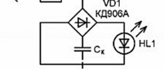
You can buy a ready-made LED, which will start blinking when the supply voltage is applied. In such a device, in addition to the usual pn junction, there is a built-in electronic circuit made according to the following principle:
The basis of the device is a master oscillator. It produces pulses with a relatively high frequency - several kilohertz or tens of kilohertz. The operating frequency is determined by the parameters of the RC chain. Capacitance and resistance are constructive - they are the elements of the LED device. In this way, it is not possible to obtain a larger capacity without significantly increasing the dimensions of the device. Therefore, the RC product is small, and operation at high frequencies is a necessary measure. At a frequency of several kilohertz, the human eye does not distinguish the blinking of the LED, and perceives it as a constant glow, so an additional element is introduced - a frequency divider. By sequential division it reduces the frequency to several hertz (depending on the supply voltage). In terms of weight and size, such a solution is more advantageous than using a capacitor with a large capacity. The lowest supply voltage for a finished flashing LED is about 3.5 volts.
LED operating principle
Before connecting the LED, you need to know a minimum of theory. In the region of the pn junction, due to the existence of hole and electronic conductivity, a zone is formed with energy levels that are non-standard for the thickness of the main crystal.
When charge carriers recombine, energy is released, and if its value is equal to a quantum of light, then the junction of the two materials begins to radiate. The hue depends on certain quantities, and the relationship is as follows:
E = hc / λ, where h = 6.6 x 10⁻³⁴ is Planck’s constant, c = 3 x 10⁸ is the speed of light, and the Greek letter lambda denotes wavelength (m)
From this statement it follows that a diode can be created where the difference in energy levels is E.
This will be what you are looking for. This is how LEDs are made. And depending on the difference in levels, the color can be blue, red, green, etc.
Moreover, not all LEDs have the same efficiency. The weakest are the blue ones, which historically were one of the last to appear.
The efficiency of LEDs is relatively low (for semiconductor technology) and rarely reaches even 45%.
But with all this, the specific conversion of electrical energy into useful light energy is simply amazing.
Each watt of energy can produce 6-7 times more photons than an incandescent filament under the same consumption conditions. This explains why LEDs have a strong position in lighting technology today.
It is for this same reason that creating a flasher based on these semiconductor elements is incomparably simpler. Relatively low voltages are enough for the circuit to start working.
Everything else comes down to choosing the right key and passive elements to create a sawtooth or pulse voltage of the desired shape:
Amplitude. Duty factor. Repetition frequency.
How to do it? Obviously, connecting an LED to a 220V network will not be the best idea.
There are similar circuits, but making them blink is quite difficult, because the element base for this has not yet been created.
Typically LEDs operate from much lower supply voltages. Of these, the most accessible are:
+5 V voltage is present in chargers for telephone batteries, as well as iPads and other gadgets.
True, the output current in this case is small, but in most cases this is not necessary. In addition, +5 V can be found on one of the power supply buses of a personal computer.
In this case, there will be no problems with current limitation. The wire in this case is red, and look for the ground on black.
Voltage from +7 to +9 V is often found on chargers of hand-held radio stations, commonly called walkie-talkies.
There are a great many companies, and each has its own standards
In our opinion, the LED connection circuit will work best from +12 V.
This is a standard voltage in microelectronics and can be found in many places. The computer unit also contains a voltage of -12 V. The core insulation is blue, and the wire itself is left for compatibility with older drives.
In our case, it may be needed if the elemental base for supplying +12 V is not at hand. Then it will be enough to find complementary transistors and turn them on instead of the original ones. The ratings of the passive elements remain the same. The LED itself is also turned on by the reverse side.
The -3.3 V rating at first glance seems unclaimed.
But if you are lucky enough to get SMD0603 RGB LEDs on Aliexpress for 4 rubles apiece, then you won’t have to move mountains.
However! The voltage drop in the forward direction should not exceed 3 V (reverse switching is not needed, but in case of incorrect polarity the maximum voltage is 5).
Now that the design of the LED is completely clear to us, and the combustion conditions are known, let’s begin to implement our idea. Namely, let's make the element blink.
How to make a flashing LED
It is not difficult to make a flashing LED yourself. In many cases, only a few additional elements will be needed. Simple variants of the schemes are given below.
Flasher on one transistor
It’s easy to make such a flasher with your own hands using just one transistor.
The circuit is assembled using a unijunction transistor. You can install the domestic element KT117, or you can select a foreign analogue. The oscillation frequency is inversely proportional to the product R1C1. The nominal values and purpose of the elements are indicated in the table.
| R1 | C1 | R2 | R3 |
| From several kilo-ohms to tens of kilo-ohms. Together with C1, it sets the generator frequency. | To obtain a frequency of 1..3 Hz, you need to select a value of 10..100 µF and adjust the frequency by selecting R1. | Limits the current through the transistor and LED. Selected depending on the supply voltage, at 10 V to set the current to 10 mA, the rating must be 1 kOhm. | Several tens of ohms |
The supply voltage can range from 4.5 to 12 volts. The disadvantage of the circuit is the use of a large oxide capacitor - much larger than the LED itself. But it contains few elements and works immediately after error-free assembly. If you cannot purchase a unijunction transistor, you can make its analogue using two bipolar transistors.
You can use any two transistors of the pnp and npn structure. For example, domestic pairs KT315 and KT316, KT3102 and KT3107 or any other devices of Russian or foreign production.
Blinking LED from battery
The indicated circuit is simple, easy to manufacture, and does not require adjustment (except, perhaps, for selecting the parameters of the timing chain). But it has a feature that in some situations can become critical - it will require a voltage of 4.5 V to power it. This voltage will require a minimum of three AA batteries or CR2032. And even a slight decrease in power due to discharge can lead to inoperability of the circuit.
Almost all common light-emitting elements require a voltage of 1.6 V (and often 3 V) to glow, so it is impossible to build a simple blinking LED circuit to be powered by a 1.5-volt battery. But you can make it relatively complex - with doubling the voltage.
A generator is assembled on transistors VT1, VT2, setting the frequency and duration of the flashes (they are determined by the circuits R1C1 and C1R2, respectively). During the pause, capacitor C2 is charged almost to the supply level. During the glow, key VT3 opens, VT2 closes, and the container is connected in series with the power source. This doubles the voltage across the LED.
Diode VD1 must be germanium. On a silicon diode in the open state, the voltage drop will be about 0.6 V - in this case this is a lot.
It will be useful to read: Blinking LED without any circuits
Making LED strip
LED strip has become a popular lighting device that has become widespread. It is a flexible base on which parallel chains of series-connected limiting resistors and LEDs are applied. This tape is supplied in the form of a coil, which can be cut in certain places.
From the diagram it can be seen that the lighting device differs from a single LED by an increased supply voltage due to the sequential connection of several elements and an increased current consumption caused by the parallel connection of many chains. Therefore, the power source must be powerful enough, and therefore large. So there is no point in saving on the size of the circuit elements for building an LED strip flasher. The paradox is that for such a tape you can build a super-simple signal generator.
- flashing LED;
- current limiting resistor;
- a powerful field-effect transistor (you can use IRLU24N or similar ones that match the parameters);
- the tape itself;
- power supply.
The LED will turn on periodically, applying and removing voltage to the gate of the transistor. The key will turn on and off in time, turning the LED strip on and off. The flasher can be expanded if you need to turn on and off the second lighting device in antiphase with the first.
If one tape is on, the second will be off, and vice versa.
A separate power source can be used for each tape, but the common wire (negative line) must be connected.
This scheme has undeniable advantages - simplicity and low cost. But there is also a drawback - the frequency and duration of blinking are determined by the parameters of the LED, and they can only be changed by the supply voltage at the same time. To be able to establish separately the period of outbreaks and their duration, a more complex scheme is needed. To do this, you will need the KR1006VI1 microcircuit or its foreign equivalent NE555. Advantages of this chip:
- small sizes;
- low power consumption;
- the ability to separately adjust the duration of output pulses and the pause between them.
Testing flashing RGB LEDs
A computer power supply is almost an ideal option for testing SMD0603 LEDs.
In this case, you just need to install a resistive divider. To do this, according to the diagram from the technical documentation, the resistance of pn junctions in the forward direction is assessed using a tester.
Direct measurement is not possible here. Instead, you should assemble the circuit shown in the figure. Here are the considerations we proceeded from, and what is shown in the picture:
- The microcircuit is given along with the numbers of the legs according to the technical data.
- Power is supplied to the cathode because the polarity of the voltage is negative. 3.3 V is just enough to open the pn junctions.
- A variable resistor does not need a very large value.
In our picture it is installed with a maximum limit of 680 Ohms. This is exactly the position he should be in initially.
Usually the on-pn junction resistance is not very high, but we need a significant margin so that the diodes do not burn out (we remember that their maximum forward voltage is 3 V).
Also taken into account is the fact that at low voltage the resistance of each LED will be about 700 Ohms. When connected in parallel, the total resistance is found according to the formula shown in the figure below
Substituting 700 there as all three input parameters, we get 233 Ohms. This will be the resistance of our LEDs at the moment when they are just starting to open (at least we think so).
The bottom line is that we need to control the mode with a tester (see figure above).
To do this, we constantly measure the voltage on the LED chip, while simultaneously reducing the resistance value until the potential difference rises to 2.5 V. Further increasing the voltage is simply dangerous, perhaps many will stop even at 2.2 V.
Then, from the proportion, we find the required resistance of the LED chip: (3.3 – 2.5)/2.5 = R AC / R total, where R AC is the resistance of the variable resistor at the moment when the voltage on the tester display reaches 2.5 V. R total = 3.125 R per.
The +3.3 V wire on the computer power supply has orange insulation, and we take the circuit ground from black.
Please note that this module does not need to be turned on without load. It would be ideal to connect a DVD drive or some other device to one of the connectors
You can also simply remove the side cover and remove the necessary contacts from there.
The connection of LEDs is illustrated by the diagram. Many will ask – what next? Have you measured the resistance for parallel connection of LEDs and stopped?
Let us explain: in working condition, if you need to turn on several LEDs, we will make a similar adjustment. As a result, the supply voltage on the chip should be 2.5 V.
Please note that the LEDs are flashing so readings may not be entirely accurate.
In this case, the maximum reading should not exceed 2.5 V. Well, and, of course, it will be clear that the circuit is working, because the LEDs will start blinking.
In order for only some of them to manifest themselves in this regard, it is necessary to remove food from unnecessary ones. It is also possible to assemble a debugging circuit with three variable resistors - one in a branch of each color.
Thus, we now know how to make a flashing LED backlight with our own hands.
And now many will ask whether it is possible to vary the response time.
We believe that containers should still be used inside. Perhaps these are even the own capacitances of the pn junctions of the LEDs.
But in any case, by connecting a variable capacitor in parallel with the circuit to the input, you can try to change something.
The value must be very small and measured in pF. There simply cannot be large capacities in such a small chip.
We also assume that a resistor connected in parallel to the microcircuit (see the dotted line in the diagram above) and placed on the ground will form a more accurate divider. In this case, stability will increase.
Then you need to take more significant values, but do not forget that this will significantly limit the current flowing through the LEDs. In fact, you need to think through this issue according to the existing situation.
Flashing LED: how to make, connect and where to use
The blinking light signal is widely used - from a special mode of operation of flashlights to the indication of complex equipment. It is increasingly based on a flashing LED, as a reliable and durable alternative to any other types of light sources.
Let's consider what its principle of operation is, what ready-made solutions for such a device are available on the market today, how to make an ice element operating in normal mode begin to work in a flickering rhythm, what is the general scope of their application, as well as how to do it yourself using them make garlands and running lights.
How to connect an LED to Arduino
It is advisable to connect to the Arduino through a resistor. In arduino, connection is also possible through the built-in resistor, but this requires a special command syntax and it is better not to use it. We take the limiting resistor between the port output and the LED at 150 - 200 Ohms.
Smooth LED switching on
For smooth switching, we use the new PWM signal modulation command.
To understand the principle of operation of PWM modulation, imagine a rubber tube through which water flows into a glass. If we hold and release the tube every second, over the same period the amount of water collected will decrease by half. If you press for one second once every four seconds, we will limit the volume of liquid by a quarter.
In Arduino, the signal modulation occurs at a frequency of about 500 pulses per second.
The analogWrite(port, modulation frequency) command applies a modulated signal to the specified port. At a frequency of 255, 100% of the power is supplied, at a frequency of 127, respectively, 50%. By changing the modulation frequency we can change the brightness. For a modulated signal, analog inputs and outputs are used.
void setup() // procedure setup { pinMode (6, OUTPUT); // turn on analog port 6 as output } void loop() {
Cycle of increasing modulation frequency from 0 to 255
For (int i=0; i<=255;i++) { analogWrite(6, i); delay(20); // delay 20 milliseconds. The LED will “light up” in 5 seconds. }
Cycle of decreasing modulation frequency from 255 to 0
for(int i=255;i>=0;i—) { analogWrite(6, i); delay(20); }
In this example, the LED lights up smoothly in 5 seconds. then gradually goes out within 5 seconds.
To connect a large number of LEDs or a powerful LED, switches are required: a transistor switch, a photocoupler, a switch microcircuit. They allow you to supply power from an external source of sufficient power.
Please rate the article. We tried our best:)
Operating principle
An LED with flashing light emission is a standard LED crystal, the electrical power circuit of which includes a capacitance and a resistor that determine the operating mode. Externally, it is no different from ordinary analogues. In this case, the mechanism of its operation at the level of processes occurring in the electrical circuit comes down to the following:
- When current is applied to resistor R, charge and voltage accumulate in capacitor C.
- When its potential reaches 12 volts, a breakdown is formed at the pn boundary in the transistor. This increases conductivity, which initiates the production of light flux by the ice crystal.
- When the voltage drops, the transistor becomes off again and the process begins again.
All modules of such a circuit operate at the same frequency.
Connecting flashing and multi-color LEDs
Externally, flashing LEDs are no different from conventional analogues and can flash in one, two or three colors according to the algorithm specified by the manufacturer. The internal difference is the presence of another substrate under the housing, on which the integrated pulse generator is located. The rated operating current, as a rule, does not exceed 20 mA, and the voltage drop can vary from 3 to 14 V. Therefore, before connecting a flashing LED, you need to familiarize yourself with its characteristics. If they are not there, then you can find out the parameters experimentally by connecting to an adjustable power supply at 5–15 V through a resistor with a resistance of 51–100 Ohms.
The multicolor RGB LED housing contains 3 independent crystals of green, red and blue. Therefore, when calculating resistor values, you need to remember that each glow color has its own voltage drop.
Ready flashing LEDs
Flashing LEDs from various manufacturers are essentially functionally complete circuits, ready for use in various fields. In terms of external parameters, they are not much different from standard ice devices. However, their design includes a generator-type circuit and its accompanying elements.
Among the main advantages of ready-made flashing LEDs are:
- Compact, robust housing, all components in one housing.
- Large range of supply voltage.
- Multi-color design, wide variety of shade switching rhythms.
- Economical.
Advice! The simplest flashing LED can be made by connecting an LED crystal, a CR battery and a 160-230 Ohm resistor into one chain, observing the polarity rules.
Usage patterns
The simplest version of the circuit of LED-based flashers produced today, which can be manufactured by radio amateurs on their own, includes:
- Low power transistor.
- Polar type capacitor 16 volts and 470 microfarads.
- Resistor.
- Ice element.
When the charge accumulates, an avalanche-like breakdown occurs with the opening of the transistor module and the glow of the diode. This type of device is often used in Christmas tree garland. The disadvantage of the circuit is the need to use a special power source.
Another version of flashing type LED circuits that are popular today includes a pair of NPN transistors of the KT315 B modification. The following components are also used for its assembly:
- Two pairs of resistors for 6.8–15 kOhm and 470–680 Ohm.
- Two capacitors with a capacity of 47-100 µF.
- A small LED or a piece of ice strip.
- Power supply from 3 to 12 V.
The principle of operation of the device is determined by an alternating change in the charging/discharging cycle of capacitors, which in turn open the transistors and power the LEDs and ensure their blinking.
Conventional LEDs
The standard non-blinking LED provides bright, uniform illumination and low power consumption. Along with such qualities as durability, compactness, energy efficiency and a wide range of glow temperatures, this makes it unrivaled among other artificial light sources. A circuit of flickering lamps is assembled on the basis of such LED elements. Let's look at the principle by which they are made.
How to make LEDs blink
An LED flasher can be assembled based on one of the above presented circuits. Accordingly, you will need to purchase the components described above. They are necessary for the functioning of one or another option. In this case, for assembly you will need a soldering iron, solder, flux and other necessary components for soldering.
The assembly of a chain of flashing LEDs is preceded by mandatory tinning of the output contacts of all connected elements. Also, we must not forget about observing polarity rules, especially when connecting capacitors. The finished lamp will flicker with a frequency of about 1.5 Hz or, which is the same, about 15 pulses every 10-second period of time.
Flasher circuits based on them
In order for elementary flashes of light to occur at a certain periodicity, a pair of C945 type transistors or analog elements is required. For the first option, the collector is placed in the center, and for the second, the base is located in the middle. One or a pair of flashing LEDs are manufactured according to the usual design. In this case, the frequency of flashes is set by the presence of capacitors C1 and C2 in the chain.
It is possible to simultaneously introduce several ice crystals into such a system when installing a sufficiently powerful PNP-type transistor. In this case, the LEDs are made to blink when their contacts are connected to multi-colored elements, the sequence of flashes is set by the generator module, and the frequency is set by the specified software settings.
Application area
LEDs operating in a flashing rhythm are used in various fields:
- In the entertainment field, in toys, for decoration, as garlands.
- As an indication in household and industrial devices.
- Light signaling devices.
- In advertising elements, signs.
- Information boards.
Important! LEDs, which emit light in a blinking rhythm, are used not only in the visible range of the spectrum, but also in the infrared and ultraviolet segments. Their area of purpose is automation and remote control systems for various equipment - heating, ventilation, household appliances.
How to wipe the lamp?
If you still cannot avoid fingerprints on the glass, do not despair. Rubbing with an alcohol-containing solution can save the situation. Best suited:
- alcohol;
- cologne;
- perfume;
- nail polish remover;
- acetone;
- vodka.
Undesirable consequences can result not only from incorrectly changing the device, but also from careless maintenance. A situation often arises when dirt or dust has accumulated on the lamp. Such contact can also harm the product. Therefore, it is recommended to wipe it regularly
But this also needs to be done correctly and carefully.
Any lighting device has its own service life
It can be designed for six months or several years, but if you do not pay attention to the wishes of the manufacturers and are negligent in taking precautions, you should not complain about the poor quality of lighting or rapid breakdown
DIY LED running lights
One of the areas of use of flashing LEDs is the “running lights” device. The following components are used to assemble the circuit:
- Rectangular pulse generator.
- Display device.
- Decoder.
- Counter.
The circuit is manufactured on a solderless breadboard. At the same time, a small spread in the values of resistors and capacitors is allowed, but not more than 20%. LEDs from HL1 to HL16 may not necessarily be the same color, but different shades. However, the voltage drop of each ice element must be within 3 volts.
How to make an LED flasher with your own hands
There are many schemes that can be used to make an LED blink. Flashing devices can be made either from individual radio components or based on various microcircuits. First, we will look at the multivibrator flasher circuit using two transistors. The most common parts are suitable for its assembly. They can be purchased at a radio parts store or “obtained” from obsolete televisions, radios and other radio equipment. Also in many online stores you can buy kits of parts for assembling similar circuits of LED flashers.
The figure shows a multivibrator flasher circuit consisting of only nine parts. To assemble it you will need:
- two resistors of 6.8 – 15 kOhm;
- two resistors with a resistance of 470 - 680 Ohms;
- two low-power transistors with an npn structure, for example KT315 B;
- two electrolytic capacitors with a capacity of 47–100 μF
- one low-power LED of any color, for example red.
It is not necessary that paired parts, for example resistors R2 and R3, have the same value. A small spread in values has virtually no effect on the operation of the multivibrator. Also, this LED flasher circuit is not critical to the supply voltage. It works confidently in the voltage range from 3 to 12 volts.
The multivibrator flasher circuit works as follows. At the moment of supplying power to the circuit, one of the transistors will always be open a little more than the other. The reason could be, for example, a slightly higher current transfer coefficient. Let transistor T2 initially open more. Then the charging current of capacitor C1 will flow through its base and resistor R1. Transistor T2 will be in the open state and its collector current will flow through R4. There will be a low voltage on the positive plate of capacitor C2, connected to the collector T2, and it will not charge. As C1 charges, the base current T2 will decrease and the collector voltage will increase. At some point, this voltage will become such that the charging current of capacitor C2 will flow and transistor T3 will begin to open. C1 will begin to discharge through transistor T3 and resistor R2. The voltage drop across R2 will reliably close T2. At this time, current will flow through the open transistor T3 and resistor R1 and LED1 will light up. In the future, charge-discharge cycles of capacitors will be repeated alternately.
If you look at the oscillograms on the collectors of the transistors, they will look like rectangular pulses.
When the width (duration) of rectangular pulses is equal to the distance between them, then the signal is said to have a meander shape. By taking oscillograms from the collectors of both transistors at the same time, you can see that they are always in antiphase. The duration of the pulses and the time between their repetitions directly depend on the products R2C2 and R3C1. By changing the ratio of products, you can change the duration and frequency of LED flashes.
To assemble the blinking LED circuit, you will need a soldering iron, solder and flux. As a flux, you can use rosin or liquid soldering flux, sold in stores. Before assembling the structure, it is necessary to thoroughly clean and tin the terminals of the radio components. The terminals of the transistors and the LED must be connected in accordance with their purpose. It is also necessary to observe the polarity of connection of electrolytic capacitors. The markings and pin assignments of KT315 transistors are shown in the photo.
The easiest way to determine the cathode of an LED is by holding the device up to the light. The cathode is an electrode with a larger area. The negative terminal of the “electrolyte” is usually marked with a white stripe on the body of the device.
Depending on the tasks that the radio amateur sets for himself, the flasher circuit can be assembled “on a canopy” by connecting the terminals of the radio components to each other using pieces of thin wire. In this case, you may end up with a design similar to the one shown in the photo below.
Assembling a flasher “on the knee”
If you need to assemble a flasher for subsequent use, the installation can be done on a piece of hard cardboard or a printed circuit board can be made from PCB.
How to make a garland of LEDs
To make a garland that periodically blinks with a given rhythm, you will need the following components and a set of tools:
- LEDs 20 mAh.
- Wiring with a cross-sectional area of 0.5-0.25 mm 2.
- 6 volt transformer.
- 100 ohm resistor.
- Soldering station with a small section tip, solder, rosin.
- Knife with a sharp blade.
- Silicone based sealant.
- Felt pen.
- Determine exactly the spaces between the flashing elements.
- Prepare the wire and mark the LED marks with a felt-tip pen.
- At the marks, make cuts of the insulation with a sharp knife.
- Next, apply rosin and solder to the bare areas.
- Solder the diode electrodes to these places.
- Apply silicone sealant to exposed areas to provide electrical insulation.
Upon completion, connect the power supply and a regular resistor. The device is connected to the network and checked for functionality.
Advice! When making garlands, it must be taken into account that the exclusively sequential nature of the connection of LEDs in the circuit will provide their characteristic blinking effect.
Service life of a repaired lamp
How long will such a light bulb with a “shunted” LED last?
Everything will depend on two factors. Firstly, what is the voltage in your network (normal, high (>230V) or low).
Secondly, where is this light bulb located? If this is a corridor, toilet, utility room, barn, etc., where it is turned on for a short time, then the lamp can easily last for several months.
If this is a living room, bedroom, kitchen, then we are talking about a much shorter period.
It is believed that the missing element will cause an increase in current in the entire circuit. Which is often what actually happens.
And this already leads to the sequential failure of the remaining LEDs one after another.
But if the driver in the lamp is made of high quality and has a good pulse current stabilizer, then the operation of the lamp will be maintained for a very long time.
Here is a visual comparison of the current strength in a “shunted” lamp...
and in a lamp, where instead of a burnt-out LED, several additional resistors were soldered in, which were precisely supposed to reduce the current.
As you can see, there is practically no difference. Do you think it’s worth bothering with this and worrying about a shorter service life?
But again, we repeat, this is only if you have a good driver.
With the classic cheap power supply circuit for an LED lamp using a quenching capacitor, the service life is reduced significantly.
Current stabilization in such lamps is very conditional.
Main conclusions
A flashing LED is a standard ice element, equipped with a resistor and capacitor for a specific rhythmic glow, operating on the following principle:
- The incoming current stores charge on the resistor.
- Upon reaching the specified potential, a breakdown occurs in the pn junction of the transistor - current flows and the LED flashes.
- As the charge decreases, the transistor turns off and the process repeats.
The circuit of a common flashing homemade LED may include one or a pair of transistors. When assembling them yourself, you need to prepare in advance all the necessary components and tools required during the work. The scope of application of flickering ice lamps is huge - from toys and garlands to alarms, indications and remote control systems.
If you know how to assemble a flashing LED circuit in another way, be sure to share useful information in the comments.
Source
Key Features
Theater lighting has its own differences and is organized taking into account several basic principles that always remain the same:
- Light is not a separate element, it is part of the overall design complex and is needed to create an image of what is happening. Due to the lighting, good visibility is ensured and attention is focused on individual areas of the stage or performers.
- The lighting system cannot be static; it consists of many elements that need to be turned on or off at a certain moment in order to play with light and shadow. It is especially difficult to ensure the dynamics of the action; in this case, the perception of what is happening depends on changes in lighting.
- Concerts, performances and other events take place on the stage of the cultural center or any other institution. And at each of them you need to clearly highlight what is happening, so you need to think through everything in advance and adjust the effects during rehearsals.
- Light sources perform different functions and cannot always be used. Before choosing the type of equipment, you need to think about what compositions will be created. It is better to make a system that is easily transformed.
On a large stage, dozens or even hundreds of lamps are used.
It doesn’t matter where the lighting is done - in a theater, on a school stage, etc., the dynamics of the action must be taken into account to ensure the desired effect. It is desirable that it be possible to make changes, since static light does not give the desired effect.