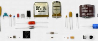
Connection methods
The most common two methods of connecting a thermocouple to measuring transducers are simple and differential. In the first case, the measuring transducer is connected directly to two thermoelectrodes. In the second case, two conductors with different thermo-EMF coefficients are used, soldered at two ends, and the measuring transducer is connected to the gap in one of the conductors.
For remote connection of thermocouples, extension or compensation wires are used. Extension wires are made of the same material as thermoelectrodes, but may have a different diameter. Compensation wires are used primarily with noble metal thermocouples and have a composition different from that of thermoelectrodes. Requirements for wires for connecting thermocouples are established in the IEC 60584-3 standard. The following basic recommendations can improve the accuracy of a measurement system that includes a thermocouple sensor:
— A miniature thermocouple made of very thin wire should only be connected using larger diameter extension wires; — Avoid, if possible, mechanical tension and vibration of the thermocouple wire; — When using long extension wires, to avoid interference, you should connect the wire screen to the voltmeter screen and carefully twist the wires; — If possible, avoid sharp temperature gradients along the length of the thermocouple; — The material of the protective cover should not contaminate the thermocouple electrodes over the entire operating temperature range and should provide reliable protection of the thermocouple wire when working in harmful conditions; — Use extension cables within their operating range and at minimum temperature gradients; — For additional control and diagnostics of temperature measurements, special thermocouples with four thermoelectrodes are used, which allow additional measurements of circuit resistance to monitor the integrity and reliability of thermocouples.
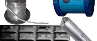
Production
Thermocouple wire chromel, alumel are produced through the technological operation of drawing, which belongs to the class of pressure processing.
During the manufacture of semi-finished products, the workpieces are not heated; accordingly, they are cold-deformed. Wire made from chromel and alumel alloys is supplied after heat treatment, that is, in a soft state. No chemical or mechanical treatment is performed.
For further use in thermocouples, it is necessary to select a specific pair of segments, the readings of which will be as close as possible to the standard values. A description of the pair selection process, as well as calibration and verification, is presented in the article Thermocouples. Types, characteristics, designs, production.
Dimensions, delivery condition, properties, measured temperature ranges for wire made of alumel and chromel are presented in the GOST 1790-77 standard, nominal static characteristics for the corresponding thermocouples - GOST R 8.585-2001.
Advantages and disadvantages of resistance thermometers
Like any device, the use of resistance thermometers has a number of advantages and disadvantages. Let's look at them.
Advantages:
- almost linear characteristic;
- measurements are quite accurate (error no more than 1°C);
- some models are cheap and easy to use;
- interchangeability of devices;
- work stability.
Flaws:
- small measurement range;
- quite low limiting temperature of measurements;
- the need to use special connection circuits for increased accuracy, which increases the cost of implementation.
A resistance thermometer is a common device in almost all industries. This device is convenient for measuring low temperatures without fear for the accuracy of the data obtained. The thermometer is not particularly durable, however, the reasonable price and ease of replacing the sensor make up for this minor drawback.
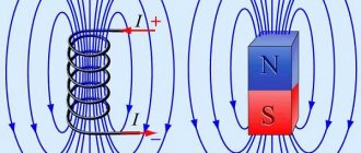
Seebeck phenomenon
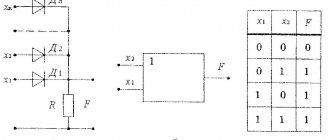
Consists of the following. If in a closed circuit of two dissimilar conductors, or better yet semiconductors, since the effect is more pronounced for semiconductors, the junctions of these conductors, commonly called junctions, are maintained at different temperatures, then current will flow in such a circuit. The direction of the current depends on which temperature of which junction is higher. With one difference in one direction, with another difference in the other.
This device, when cut in one of the places, is used as a thermocouple, temperature sensor. In diagram 2, further, junction 1 will be shown, we will heat or cool, and the other junction is inside the galvanometer, which is at room temperature. Depending on whether the temperature of junction T1 is higher than room temperature or lower, the galvanometer needle will deviate either in one direction or the other.
If both wires in the thermocouple circuit are made of the same material, then nothing will happen. It’s very simple to check this, take two copper wires with insulation, no one has canceled the safety measures, connect them with one end to the galvanometer, and twist the other ends together (but it’s better to solder), and start heating, you can also put them in water with pieces of ice. If you took the same wires, then the needle of the device will remain at zero. But if you take different wires and connect them to the device in the same way, and twist the other ends. And after that, if you heat or cool the bare ends of the wires, you will be able to observe how and in which direction the galvanometer needle will deviate.
What is the difference between chromel and alumel?
Alumel has magnetic properties, plus is a negative element, and chromel is the opposite, i.e. positive and not magnetic.
Characteristics of chromel wire
The main elements of chromel wire are nickel (89-91%) plus chromium (8.5 to 10%). In addition to cobalt, which is necessarily included in the composition (about 1.2%), iron, aluminum, magnesium, manganese and others are added to the alloy in small quantities. The percentage of impurities is 1.4. Here are some basic characteristics of the alloy:
- melting point is 1400-1500 ᵒC;
- electrical resistivity – 0.66 μΩ×m;
- coefficient of linear expansion – 12.8×10⁻⁶ °C-1;
- annealing temperature ranges from 800-900 ᵒC;
- hardness – НВ 10-1=150-200 MPa;
- tensile strength is 600-700 MPa.
Also, Chromel thermocouple wire is characterized by an electromotive force approaching zero.
Depending on the marking of the alloy, the composition of chromel may differ slightly. The same applies to alumel.
Characteristics of alumel wire
The composition of alumel wire is somewhat different from chromel. The main element is also nickel (93-96%). The alloy also includes manganese (from 1.8 to 2.7%), aluminum (from 1.6 to 2.4%), silicon (from 0.8 to 1.4%) plus cobalt (up to 1.2% ).
Thanks to the aluminum present in the composition, the alloy is heat-resistant and less susceptible to corrosion in various aggressive environments. And some more properties of alumel:
- melting point 1430-1450 ᵒС;
- density 8480 kg/m3;
- annealing temperature ranges from 900 to 950 ᵒС;
- Brinell hardness – 130 MPa;
- electrical resistivity – 3.2×10⁻⁸ Ohm×m;
- tensile strength in the range of 500-600 MPa;
- hot processing temperature – 1000-1250 ᵒС.
What kind of device is this?
A thermocouple is a special device that is used to measure the temperature of a working medium. Such a device is widely used in industry, medicine and other areas of human activity. However, wherever high measurement accuracy is required.
From a design point of view, these are two different conductors that are soldered (or welded) to each other at one end. The place where they connect is called a junction. And different materials are used as conductors, and depending on this, the range of temperatures measured by a thermocouple ranges from -250 ᴼC to 2000 ᴼC, or even more. In most cases these are metals; semiconductors are used less frequently.
TCA (chromel-alumel) is the leader among thermocouples made of nickel alloys
Depending on the operational tasks and the characteristics of the physical and chemical properties of the objects of application (media), thermocouples of various types are used, the electrodes of which are made of certain metals/alloys.
However, of all existing combinations of conductors, thermocouples with electrodes made of nickel-based alloys have the most optimal thermoelectric characteristics. Due to the high percentage of nickel, thermocouple wire made from its alloys exhibits a high degree of resistance to the negative effects of oxidation processes and is characterized by a near-linear thermo-emf characteristic in the temperature range from 0°C to 1100°C (depending on the thickness of the thermoelectrode wire), which ensures accuracy indications.
The most common among thermocouples with nickel-containing electrodes are those in which a chromel alloy (89-91% Ni + 8.7-10% Cr) is used for the positive electrode marked green, and an alumel alloy (94) is used for the negative electrode (white marking). .5% Ni + 5.5% Al, Si, Mn, Co). These thermocouples, which have the letter “K” according to the international classification IEC (IEC), are called chromel-alumel thermocouples (TCA).
Applications of thermocouples
For measuring the temperature of various types of objects and environments, as well as as a temperature sensor in automated control systems. Tungsten-rhenium alloy thermocouples are the highest temperature contact temperature sensors available. Such thermocouples are indispensable in metallurgy for monitoring the temperature of molten metals.
For flame control and protection against gas contamination in gas boilers and other gas appliances (for example, household gas stoves). The thermocouple current, heated by the burner flame, keeps the gas valve open. If the flame fails, the thermocouple current decreases and the valve shuts off the gas supply.
In the 1920s and 1930s, thermocouples were used to power simple radios and other low-current devices. It is quite possible to use thermal generators to recharge the batteries of modern low-current devices (phones, cameras, etc.) using open fire.
Radiation receiver
Close-up of the thermopile of the photodetector. Each of the wire corners represents a thermocouple.
Historically, thermocouples represent one of the earliest thermoelectric radiation receivers. Mentions of this use date back to the early 1830s. The first receivers used single wire pairs (copper - constantan, bismuth - antimony), the hot junction was in contact with a blackened gold plate. Later designs began to use semiconductors.
Thermocouples can be connected in series, one after the other, forming a thermopile. In this case, hot junctions are located either around the perimeter of the receiving area or evenly along its surface. In the first case, individual thermocouples lie in the same plane, in the second they are parallel to each other.
Advantages of thermocouples
- High accuracy of temperature measurement (up to ±0.01 °C).
- Large temperature measurement range: from −250 °C to +2500 °C.
- Simplicity.
- Cheapness.
- Reliability.
Flaws
- To obtain high accuracy of temperature measurement (up to ±0.01 °C), individual calibration of the thermocouple is required.
- The readings are affected by the riser temperature, which must be corrected for. Modern thermocouple-based meter designs use the measurement of the cold junction block temperature using a built-in thermistor or semiconductor sensor and automatically correct for the measured emf.
- Peltier effect (at the time of taking readings, it is necessary to exclude the flow of current through the thermocouple, since the current flowing through it cools the hot junction and heats up the cold one).
- The dependence of TEMF on temperature is significantly nonlinear. This creates difficulties when developing secondary signal converters.
- The occurrence of thermoelectric inhomogeneity as a result of sudden temperature changes, mechanical stresses, corrosion and chemical processes in conductors leads to changes in the calibration characteristics and errors of up to 5 K.
- Over long lengths of thermocouple and extension wires, an “antenna” effect may occur to existing electromagnetic fields.
Features of the use of the most common thermocouples
Technical characteristics depend directly on the materials from which they are made.
Type J (Iron Constantan Thermocouple)
- It is not recommended to use below 0°C, because Moisture condensation on the iron terminal leads to the formation of rust.
- The most suitable type for rarefied atmospheres.
- The maximum temperature of use is 500°C, because Above this temperature, rapid oxidation of the leads occurs. Both terminals are quickly destroyed in a sulfur atmosphere.
- The readings increase after thermal aging.
- Low cost is also an advantage.
Type E (chromel-constantan thermocouple)
- The advantage is high sensitivity.
- Thermoelectric homogeneity of electrode materials.
- Suitable for use at low temperatures.
Type T (copper-constantan thermocouple)
- Can be used below 0°C.
- Can be used in atmospheres with slight excess or deficiency of oxygen.
- Use at temperatures above 400°C is not recommended.
- Not sensitive to high humidity.
- Both leads can be annealed to remove materials causing thermoelectric inhomogeneity.
Type T thermocouples.
Type K (chromel-alumel thermocouple)
- Widely used in various areas from -100°C to +1000°C (recommended limit depending on the diameter of the thermoelectrode).
- In the range from 200 to 500°C, a hysteresis effect occurs, i.e., readings during heating and cooling may differ. Sometimes the difference reaches 5°C.
- Used in a neutral atmosphere or an atmosphere with excess oxygen.
- After thermal aging, the readings decrease.
- It is not recommended to use in a rarefied atmosphere, because... chromium can be released from the Ni-Cr terminal (so-called migration), and the thermocouple changes the thermoelectric force and shows a low temperature.
- A sulfur atmosphere is harmful to a thermocouple because affects both electrodes.
Type K thermocouple.
Type N (nicrosil-nisil thermocouple)
- This is a relatively new type of thermocouple, developed from the K-type thermocouple. The K-type thermocouple can be easily contaminated by impurities at high temperatures. By fusing both electrodes with silicon, the thermocouple can be precontaminated and thus reduce the risk of further contamination during operation.
- Recommended operating temperature up to 1200°C (depending on wire diameter).
- Short-term operation is possible at 1250°C.
- High stability at temperatures from 200 to 500°C (significantly less hysteresis than for a type K thermocouple).
- Considered to be the most accurate base metal thermocouple.
Type N thermocouple.
General Tips for Selecting Base Metal Thermocouples
- Application temperature below zero – type E, T
- Room temperatures for use – type K, E, T
- Application temperature up to 300°C – type K
- Application temperature from 300 to 600°C – type N
- Application temperature above 600°C – type K or N
Precious metal thermocouples
Recommended maximum operating temperature 1350°C. Short-term use is possible at 1600°C. It becomes contaminated at temperatures above 900°C with hydrogen, carbon, and metallic impurities of copper and iron. When the iron content in the platinum electrode is 0.1%, TEMF changes by more than 1 mV (100°C) at 1200°C and 1.5 mV (160°C) at 1600°C. The same picture is observed with copper contamination. Thus, thermocouples should not be reinforced with steel tube, or the electrodes should be insulated from the tube with gas-tight ceramics. Can be used in oxidizing atmosphere. At temperatures above 1000°C, the thermocouple may become contaminated with silicon, which is present in some types of protective ceramic materials
It is important to use ceramic tubes consisting of high purity aluminum oxide. It is not recommended to use below 400°C, since the thermoelectric force in this region is small and extremely nonlinear.
Precious metal thermocouples
Type B (platinum-platinum-rhodium)
Recommended maximum operating temperature is 1500°C (depending on wire diameter). Short-term use is possible up to 1750°C. Can be contaminated at temperatures above 900°C by hydrogen, silicon, copper and iron vapor, but the effect is less than for S and R thermocouples. At temperatures above 1000°C the thermocouple can be contaminated by silicon, which is present in some types of protective ceramic materials
It is important to use ceramic tubes consisting of high purity aluminum oxide. Can be used in oxidizing environments. Application is not recommended at temperatures below 600°C, where the emf is very small and nonlinear.
Mode of production
Chromel and alumel are among the most labor-intensive to produce. The complexity of the technological process lies in the need for strict control of the proportions of components during melting, since the key characteristics of the final product are determined mainly by the ratio of materials. The compositions are produced in induction furnaces of various frequencies.
The melting order is as follows. Most of the chrome is loaded into a liquid bath, leaving a few kilos for correction. Then nickel and flux are introduced at the same time. Melting is carried out in intensive mode. Metal deoxidation is carried out by adding manganese and magnesium. Then the thermoelectromotive force is determined and the chromium content is adjusted.
Other nickel alloys are produced in a similar way. The differences lie in the order of loading materials and oxidizing agents. For example, the production of alumel alloy is carried out as follows. Nickel and flux are loaded, followed by the remaining components. Magnesium is used as an oxidizing agent. This is how alumel alloys, chromel and copel are obtained.
Characteristics of chromel and alumel alloys
Before proceeding to a more detailed description of TCA, we will consider the main operational properties/parameters of chromel and alumel alloys.
Chromel is a thermoelectrode alloy that includes about 90% nickel, 9-10% chromium, and also, in total, up to 1.5% copper, cobalt, manganese, iron and silicon. For TCA electrodes, thermocouple wire Chromel NX 9.5 (GOST 492-2006), Ø 1.3 - 3.3 mm is mostly used.
The specific density of the alloy is 8.7 g/cm3, and the melting temperature is 1450°C. The indicators of the coefficients of resistivity and linear expansion are, respectively, 0.65 μOhm mm2/m and 12.7 10-6/°C.
The advantages of the chromel alloy are:
- high nickel content, which provides good malleability, ductility and corrosion resistance;
- successful combination of low specific gravity and high heat resistance;
- the electrical potential generated during the heating process at the point of contact with the negative electrode is characterized by an almost linear change over a wide temperature range;
- The thermo-emf of a chromel thermocouple remains virtually unchanged at temperatures up to 1000°C.
Alumel is an alloy for the manufacture of TCA negative electrodes. For this purpose, thermocouple wire alumel NMtsAk 12-2-1, GOST 492-2006 (about 95% nickel, 2.5% aluminum, 1.9% manganese and 0.9% silicon) is most often used. Specific density - 8.5 g/cm3, resistivity - 0.32 μOhm mm2/m; linear expansion – 13.5·10-6°C. Melting temperature is 1425°C.
In order to increase the ductility, strength and stability of thermo-emf when measuring temperatures above 1000°C in a particular aggressive environment, alumel can be alloyed with zirconium, boron and some other chemical elements.
Sources of measurement error
External sources, technical condition of measuring instruments and other conditions influence the correct measurement process.
The accuracy of measurement using a thermoelectric converter is affected by changes in electromotive force. This phenomenon is called thermoelectric instability of the alloys used. During operation, it became known that electrode alloys change their EMF, which leads to distortion of readings.
During long-term operation at high temperatures, such errors can reach large values, which leads to a decrease in measurement accuracy.
The main reasons for measurement instability are:
- interaction of thermoelectrodes with the external environment;
- influence of isolating and protective devices on sensors;
- interaction of electrodes with each other;
- internal processes that occur when temperature changes;
- influence of radiation, electromagnetic fields and pressure drops.
Under the influence of high temperature, the insulation resistance of the sensors decreases, which leads to distortion of measurements. Often the source of errors in measurements is the incorrect choice of thermoelectrode, since its resistance does not coincide with the readings of the electrical circuit. A change in the electromotive force along the length of the thermoelectric converter also leads to errors when obtaining indicators.
Pros and cons of the device
The thermocouple is the oldest and still the most common temperature sensor in the industry. The operation of a thermocouple is based on an effect that was first discovered and described by Thomas Seebeck in 1821 - the occurrence of current in a closed circuit of two dissimilar conductors in the presence of a temperature gradient between the junctions.
Since the generation of thermo-EMF occurs along the length of the thermoelectrode, the thermocouple readings depend on the state of the thermoelectrodes in the zone of maximum temperature gradient. Therefore, verification of thermocouples should be carried out at the same depth of immersion in the medium as at the work site. Taking into account thermoelectric inhomogeneity is especially important for working thermocouples made of base metals.
Pros and cons of thermocouple
Wide operating temperature range, they are the highest temperature contact sensors available.
The thermocouple junction can be directly grounded or brought into direct contact with the object being measured.
Ease of manufacture, reliability and structural strength.
The need to control the temperature of the cold junctions.
Over long lengths of thermocouple and extension wires, an “antenna” effect may occur to existing electromagnetic fields.
The dependence of Thermo-EMF on temperature is significantly non-linear. This creates difficulties when developing secondary signal converters.
Modern thermocouple-based meter designs use the measurement of the cold junction block temperature using a built-in thermistor or semiconductor sensor and automatically apply a correction to the measured Thermo-EMF. The occurrence of thermoelectric inhomogeneity in conductors and, as a consequence, a change in the calibration characteristic due to changes in the composition of the alloy as a result of corrosion and other chemical processes.
It will be interesting➡ What is electromotive force (EMF) and how to calculate it
The electrode material is not chemically inert and, if the thermocouple body is not tightly sealed, it may be exposed to aggressive environments, atmosphere, etc. When stringent requirements are placed on the thermal inertia of the thermocouple and the operating junction must be grounded, the signal converter must be electrically isolated to eliminate the risk of ground leaks.
Depending on the materials of thermoelectrodes, thermocouples made of noble and base metals are distinguished. The first include platinum group thermal converters (TPP, TPR). The ignoble ones include TVR, THA, TKhK, TMK, TNN, TZhK and others from mass-produced ones.
Checking the operation of the thermocouple
If the thermocouple fails, it cannot be repaired. Theoretically, of course, it can be repaired, but whether the device will then show the exact temperature is a big question.
Sometimes the thermocouple malfunction is not obvious and obvious. In particular, this applies to geysers. The principle of operation of a thermocouple is still the same. However, it performs a slightly different role and is not intended to visualize temperature readings, but to operate the valves. Therefore, in order to identify a malfunction of such a thermocouple, it is necessary to connect a measuring device (tester, galvanometer or potentiometer) to it and heat the thermocouple junction. To do this, it is not necessary to hold it over an open fire. It is enough to just hold it in your fist and see if the arrow of the device deviates.
The reasons for failure of thermocouples can be different. So, if you do not put a special shielding device on a thermocouple placed in a vacuum chamber of an ion-plasma nitriding installation, then over time it will become more and more fragile until one of the conductors breaks. In addition, the possibility of malfunction of the thermocouple due to changes in the chemical composition of the electrodes cannot be ruled out. After all, the fundamental principles of thermocouple operation are violated.
Gas equipment (boilers, dispensers) is also equipped with thermocouples. The main reason for electrode failure is oxidation processes that develop at high temperatures.
In the case where the instrument readings are deliberately false, and weak clamps were not detected during an external inspection, the reason most likely lies in the failure of the control and measuring instrument. In this case, it must be sent for repair. If you have the appropriate qualifications, you can try to troubleshoot the problem yourself.
And in general, if the potentiometer needle or digital indicator shows at least some “signs of life”, then the thermocouple is working. In this case, the problem clearly lies somewhere else. And accordingly, if the device does not react in any way to obvious changes in temperature, then you can safely change the thermocouple.
However, before removing the thermocouple and installing a new one, you need to be completely sure that it is faulty. To do this, it is enough to ring the thermocouple with a regular tester, or even better, measure the voltage at the output. Just a regular voltmeter is unlikely to help here. You will need a millivoltmeter or tester with the ability to select a measurement scale. After all, the potential difference is a very small value. And a standard device won’t even sense it or record it.
Stamps
The products are made from thermoelectrode nickel alloys chromel and alumel.
The first is designated by the brand NX 9.5, the second by NMtsAK 2-2-1. The main component of chromel is nickel (Ni), the proportion of which is about 87.4-90.4%, including 0.6-1.2% cobalt (Co). The second most abundant element is chromium (Cr) - 9.0-10.0%. The remaining chemical elements are contained in tenths and thousandths of a percent.
Alumel consists of 91.5-95.1% nickel (Ni), and this range also includes 0.6-1.2% cobalt (Co). The proportion of manganese (Mn), aluminum (Al) and silicon (Si) is 1.8-2.7%, 1.6-2.4% and 0.85-1.5%, respectively, the remaining elements are represented by tenths and hundredths fractions of a percent.
The chemical composition of the NH 9.5 and NMtsAK 2-2-1 grades is regulated by the GOST 492-2006 standard.
Working principle of thermocouple
A thermoelectric converter consists of two conductors (A and B), which are made of different metals (alloys). They are combined into a single electrical circuit. The connection points (t1 and t2) are placed in zones with different temperatures. This action initiates the generation of electromotive force (current).
Diagram explaining the principle of operation of a thermocouple
Notes:
- A (B) – positive (negative) electrode, respectively;
- t1 – “hot junction”, which is installed in an area with high temperature;
- t2 – “cold junction” located outside for connecting measuring instruments.
For your information. The phenomenon discussed above is called the “Sebeck effect” after the name of the scientist who made the discovery. He was able to formulate a conclusion about the main principles of constructing measuring instruments.
Principle of operation
The operation of any thermocouple is based on the thermoelectric effect, which was discovered by T.I. Seebeck back in 1821. This effect lies in the fact that if two dissimilar metal conductors are connected in series with each other, thus forming a closed electrical circuit, and heating is applied at one junction of the conductors, then an electromotive force (EMF) appears in the circuit. This electromotive force is called thermo-emf. Under the influence of thermo-EMF, an electric current begins to flow in a closed circuit.
How does a thermocouple work?
The heating point is usually called the hot junction. A place where there is no heating is a cold junction. If you connect a galvanometer or microvoltmeter to the open circuit, you can measure the value of the thermo-EMF, which will be several milli- or microvolts. The value of thermo-EMF will depend on the amount of heating at the junction of the conductors and on the temperature at the junction of the conductors, where heating does not occur. Those. the value of thermo-emf depends on the temperature difference between the cold and hot junction. Also, thermo-EMF depends on the type of conductors themselves.
It will be interesting➡ Direct current - definition and parameters
Thus, if the junction of dissimilar conductors of a thermocouple is heated, then a potential difference will arise between the unconnected (free) ends of the conductors, which can be measured with an electrical measuring instrument. Thanks to modern converters, the resulting potential difference can be converted into a specific digital value, i.e. it is quite possible to find out the value of the heating temperature at the junction of the thermocouple conductors. For accurate measurements, the cold junction temperature must remain constant. Because This is not always possible; special compensation circuits are used to compensate for the temperature of the cold junction.
Thermocouple device.
Device design
Modern thermocouples are manufactured in various shapes and lengths. According to their design, they can be divided into two groups:
- open-frame thermocouples;
- thermocouples with a protective casing.
The first are a product in which the junction of two conductors is not closed and not protected from external influences. This design allows for fast temperature measurement times and low inertia. The second type of thermocouple is available in the form of a probe. The probe is a metal tube with an internal insulator that can withstand high temperatures. A thermoelectric thermocouple element is placed inside the probe. Thanks to this design, the thermoelement is protected from the influence of aggressive environments of various technological processes.
Type J thermocouple.
Cold junction
The cold junction is often the point where the free ends of the thermocouple wires are connected to the meter. Since the thermocouple circuit meter is actually measuring the voltage difference between the two junctions, the cold junction voltage must be kept as constant as possible. By maintaining the voltage at the cold junction at a constant level, we thereby ensure that a deviation in the readings of the measuring device indicates a change in the temperature at the working junction.
If the temperature around the cold junction changes, the voltage across the cold junction will also change. As a result, the voltage at the cold junction will change. And as a result, the difference in voltage at the two junctions will also change, which will ultimately lead to inaccurate temperature readings. In order to keep the cold junction temperature constant, many thermocouples use compensating resistors. The resistor is in the same location as the cold junction, so the temperature affects the junction and the resistor at the same time.
Gas stove thermocouple.
Working junction of thermocouple (hot)
A service junction is a junction that is exposed to the process whose temperature is being measured. Due to the fact that the voltage generated by a thermocouple is directly proportional to its temperature, when the working junction is heated, it generates more voltage, and when cooled, less.
What does a thermocouple consist of?
How to check the thermostat operation
To check the thermostat, you can use the following method: when changing the temperature setpoint, characteristic clicks should be heard when passing a temperature value equal to the ambient temperature - closing and opening of contacts.
If the thermostat is removable, then you can try to heat its sensitive element and check the operation.
If, for example, we consider the thermostat in the oven, then by setting a certain temperature, after warming up, you can observe the burner flame: if it decreases and remains at the same level, then everything is in order. The accuracy of the result obtained can be achieved using a thermometer.
You can use a thermometer or a multimeter with a thermocouple to ensure that the thermostat set point is operating correctly. This method is suitable, for example, for a washing machine. A tester will also help, which, when connected to the thermostat contacts, will show their closing and opening.
How does a thermocouple work with a gas boiler?
Thermocouple - what is it? Everything becomes clear to the user when interruptions in the operation of gas equipment occur. The working junction of the thermocouple in the boiler is heated by the igniter flame. A thermo-EMF equal to 20-25 mV is induced in the circuit, the value of which is sufficient to trigger the solenoid valve. This opens the gas supply to heat the boiler. The pilot burner is always operational while the boiler is running. It lights the main burner, which heats the water. A thermocouple for a gas stove is also necessary to ensure electric ignition on the burners.
In addition, some stoves provide protection in the event of supply failures, when gas is lost in the network and then supplied again.
When the gas torch burns in the boiler, the junction of the thermoelectrodes remains heated, and due to this, the fuel supply is ensured. After the flame goes out, the working junction of the thermocouple cools down and it stops producing current. In this case, an emergency shutdown of the solenoid valve that shuts off the gas occurs.
The design and principle of operation of a thermocouple
Indeed, not every material can be constantly in the open flame zone. The thermoelement is made of metal, or rather, of several metals, so it is not afraid of high temperatures. When operating a gas boiler installation, there is no way to do without it; failure of the thermocouple means a complete shutdown of the unit and immediate repairs. The thing is that the thermoelement works in conjunction with an electromagnetic shut-off valve that closes the entrance to the fuel path. As soon as this part fails, the valve will close, the fuel supply will stop and the burner device will go out.
To better understand the principle of operation of a gas boiler thermocouple, it is worth considering the diagram presented in the figure.
Thermocouple circuit
This principle is based on the following physical phenomenon: if you reliably connect 2 dissimilar metals together, and then heat the junction, then a potential difference, that is, voltage, will appear at the cold ends of this junction. And when a measuring device is connected to them, the circuit will close and a direct electric current will arise. The voltage will be very small, but this is quite enough for induction to occur in the sensitive coil of the solenoid valve and it to open, allowing fuel to pass to the igniter.
For reference. Some modern solenoid valves are so sensitive that they remain open until the input voltage drops below 20 mV. The thermocouple in normal operating mode produces a voltage of about 40-50 mV.
Accordingly, the device of a gas boiler thermocouple is based on the described phenomenon, called the Seebeck effect. Two parts made of different metals are firmly connected to each other at one or more points, and the quality of the connection plays a big role. It affects the operating parameters of the element and the durability of its operation. The connection point will be the very working part placed in the open fire zone.
Since many different pairs of metals are used for the manufacture of thermoelements, without going into details, we note that the thermocouple for a gas boiler uses a chromel - aluminum pair. Conductors enclosed in a protective sheath are welded to the cold ends of these metals. The second end of the conductors is inserted into the corresponding socket of the unit automation and secured with a clamping nut.
In the process of igniting the igniter and burner of a gas boiler to supply fuel, we open the solenoid valve manually by pressing its rod. The gas enters the igniter and is ignited, and the thermocouple is located nearby and is heated by its flame. After 10-30 seconds, the button can be released, since the thermoelement has already begun to generate voltage that keeps the valve stem open.
How the device works
The principle of operation of a thermocouple is based on a phenomenon that was discovered by German physicist Thomas Johann Seebeck in 1821. He noticed that if two connected conductors made of dissimilar materials are heated, a voltage arises, which is called thermoEMF. Moreover, its value depends on the degree of heating at the junction of these conductors. Subsequently, the effect received the name of its discoverer.
For example, when heating iron, a positive voltage of 15 μV is generated for every 1 °C, while in nickel a negative current value of -20.8 μV is created. Since in most cases an alloy of alumel and chromel is used, when heated to a temperature of 300 °C, the “duet” of these metals produces a voltage of 12 mV.
This is quite enough to trigger the electromagnetic relay, which keeps the safety valve open. But as soon as the temperature drops (which happens almost instantly), the relay turns off, causing the valve to close.
This explanation of the principle of operation of a thermocouple in simple words will be quite understandable to many.
Design and principle of operation
It is known that in a closed circuit, which consists of two conductors of different metals (for example, chromel and copel), a thermoelectromotive force (EMF) arises, provided that their hot and cold junctions have different temperatures (Seebeck effect). The value of the EMF depends on the materials of the conductors, the temperatures of their cold and hot junctions.
Typically, the voltage of a household thermocouple is in the range of 20-60 millivolts (mV), which is enough to open the gas valve, but, of course, not enough to operate complex automation and other modules that already require an electrical connection.
This is what a standard thermocouple looks like in the photo.
The module is not limited to a pair of junctions, but the thermocouple device is quite simple and understandable:
- The sleeve, inside of which there are thermoelectrodes with the “hot” junction of the conductors, is what is attached to the burner module of the boiler, next to the pilot burner (igniter).
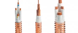
- An extension cord, protected by a copper tube from external influence of electromagnetic fields, is used to connect the working part (hot junction) with the electromagnetic gas valve.
- A dielectric washer with a “cold” junction, it is this that is inserted into the socket of the gas solenoid valve.
Most often, thermocouples of domestic gas boilers use junctions made of chromel and alumel (TCA), chromel and copel (TCC), and iron and constantan (TLC). All alloys used, their markings and characteristics are listed in the table below.
| Thermocouple type (European classification) | Junction conductor materials | Russian markings | Temperature range, °C |
| K | chromel-alumel | THA | -200 – 1 300 |
| L | chromel-copel | THC | -200 – 850 |
| J | iron-constantan | TZHK | -100 – 1 200 |
| N | nikhrosil-nisil | TNN | -200 – 1 300 |
| T | copper-constantan | TMKn | -200 – 400 |
| E | chromel-constantan | THKn | 0 – 600 |
| S | platinum-rhodium-platinum | TPP10 | 0 – 1 700 |
How does a thermoelectric thermometer work as part of a gas boiler?
The operating principle of a thermocouple in a gas boiler is the same everywhere:
- First, a person mechanically opens the gas supply valve by holding the solenoid valve button for 15-30 seconds.
- Then the piezo ignition button is pressed once, a spark appears and the pilot burner lights up.
- The magnetic valve button is held down for another 30-60 seconds until the working junction of the thermocouple, located next to the igniter, heats up and produces the required voltage.
- After 30-60 seconds, the solenoid valve button is released, but combustion continues as the heated thermocouple produces enough voltage to hold the gas valve open. The boiler operates normally, without human intervention.
- Once combustion stops, the flame no longer heats the thermocouple, causing the voltage to be insufficient to hold the gas solenoid valve open and it closes, stopping the flow of gas.
Chromel-aluminum thermocouples
These thermocouple circuits are used in most cases for the production of various sensors and probes that allow temperature control in industrial production.
Their distinctive features include a fairly low price and a huge range of measured temperatures. They allow you to record temperatures from -200 to +13000 degrees Celsius.
It is not advisable to use thermocouples with such alloys in workshops and facilities with a high sulfur content in the air, since this chemical element negatively affects both chromium and aluminum, causing disturbances in the functioning of the device.
Chromel-alumel thermocouple - briefly about the basics
As you know, a thermocouple consists of two conductors made of different materials connected at one end, which are part of a device for measuring temperature.
There are various combinations of conductors, but the most optimal thermoelectric characteristics are demonstrated by a connection made of two nickel alloys: chromel and alumel. The fact is that it is these materials that demonstrate the thermoelectric characteristic closest to direct, which is necessary to ensure high measurement accuracy. Before moving on to a description of the properties of thermocouples, we should dwell on the alloys used in them. Chromel (HX9.5) is an alloy of 89-91% nickel and 8.7-10% chromium. The rest is occupied by impurities of materials such as silicon, copper, manganese and cobalt, with the content of the latter ranging from 0.6 to 1.2%.
Alumel (NMtsAk2-2-1) consists of 93-96% nickel and 1.8-2.5% aluminum, with a high content of manganese (1.8-2.2%) and silicon (0.8-1.2 %). This alloy is quite magnetic, unlike low-magnetic chromel.
The high nickel content means that thermocouple wire made from these alloys is highly resistant to oxidation. And, given that a thermocouple made of these materials has an almost linear dependence of thermoelectromotive force (thermo-emf) in the range from 0 to 1000°C, it is often used in various thermostats.
Thermocouple made of chromel and alumel is characterized by high inertia
For short-term measurements, the maximum temperature can reach 1300°C. The material for thermocouple electrodes is thermoelectrode wire, the size range of which consists of the following diameters (GOST 1790-77): 0.2; 0.5; 0.7; 1.2; 3.2 millimeters. At a temperature of 1300 °C, only wire with a diameter of 1.2 and 3.2 mm is used.
Chromel and alumel wires are insulated from each other and from the body by ceramic single-channel insulators with ceramic tips at the end, protecting them from contact with the metal case.
Thermocouple made from these alloys is characterized by high inertia. An exception is chromel-alumel thermocouples of types TX-VII and TXA-U-XV with low inertia. Alumel and chromel wires are generally resistant to mechanical damage, except for those used in TXA-420 and TXA-430 thermocouples, which have increased resistance to vibration loads.
Most thermocouples have a standard head design, but there are also options with waterproof and splashproof heads. THAP thermocouples do not have a head. A flexible hose or fitting is used to enter the wires.
One of the main advantages of thermoelectrode wires made of chromel and alumel is their resistance to oxidation, which allows them to work reliably in an oxidizing environment due to the appearance of a thin protective film when heated, which prevents the penetration of oxygen into the metal. But it should be taken into account that long-term operation of a thermocouple in an oxidizing environment can lead to some change in thermo-emf, especially at temperatures of 300-500 and 800-1000°C. It is not recommended to use them in an atmosphere with a high sulfur content, which negatively affects both materials - chromel and alumel.
Chromel-alumel thermocouples are popular because of their affordability, as well as the complexity of manufacturing and a fairly wide range of measured temperatures, depending on the diameter of the thermoelectrode wire.
Literature
- Thermocouple // Lake Teletskoye - Trichophytosis. - M.: Soviet Encyclopedia, 1946. - (: / chief editor O. Yu. Shmidt; 1926-1947, vol. 54).
- Keyes R. J., Kruse P. W., Patley E. G., Long D., Zwicker G. R., Milton A. F., Teich M. K.
§ 3.2. Thermocouple // Photodetectors of the visible and IR ranges = Optical and Infrared Detectors / trans. from English edited by V. I. Stafeeva. - M.: Radio and Communications, 1985. - 328 p.
H. Melloni. Ueber den Durchgang der Wärmestrahlen durch verschiedene Körper (German) // Annalen der Physik und Chemie: journal. - Leipzig: Verlag von Johann Ambrosius Barth, 1833. - Bd. 28. - S. 371-378.
Grunin V.K. § 2.3.4. Thermoelectric radiation receivers // Sources and receivers of radiation: textbook. - St. Petersburg: Publishing house of St. Petersburg Electrotechnical University "LETI", 2015. - 167 p. — ISBN 978-5-7629-1616-5.
Thermocouple installation
To minimize the negative effects noted above, the thermocouple is connected with wires made of the same materials that were used to make the positive (negative) electrode. Be sure to maintain correct polarity. The measuring unit (transducer) is placed at a short distance. Data from it in digital form enters the computer center for indication of readings and subsequent processing.
Wiring diagrams
Temperature measurement at control points (1) is used to create compensation voltage. If devices are connected to open circuit (2), select conductors with the same parameters.
Thermocouple designs
There are two main types of thermocouple designs.
- Using an insulating layer. This thermocouple design provides for isolating the working layer of the device from electric current. Such a scheme allows the use of a thermocouple in a technological process without isolating the input from the ground.
- Without the use of an insulating layer. Such thermocouples can only be connected to measuring circuits whose inputs do not have contact with ground. If this condition is not met, two independent closed circuits will appear in the device, as a result of which the readings obtained using a thermocouple will not correspond to reality.
Recommendations for use
The accuracy and integrity of a thermocouple sensor-based measurement system can be increased if certain conditions are met. Avoid vibrations and mechanical tension on thermocouple conductors. When using a miniature thermocouple made of thin wire. It should only be used in a controlled location, and extension leads should be used beyond that location. It is recommended to use large diameter wire that does not change the temperature of the measured object. Use the temperature sensor only within the operating temperature range.
Table - Calibration and testing of thermocouples.
Avoid sudden temperature changes along the length of the temperature sensor. When working with long temperature sensors and extension conductors, it is necessary to connect the voltmeter screen to the wire screen. For auxiliary control and temperature diagnostics, special temperature sensors with 4 thermoelectrodes are used, which allow auxiliary measurements of temperature, resistance, voltage, interference to check the reliability and integrity of thermocouples.
Carry out electronic recording of events and constantly monitor the resistance value of thermoelectrodes. Use extension conductors within the operating range and at the smallest temperature differences. Use a quality protective cover to protect the thermocouple leads from harmful conditions.
Types of sensors and their characteristics
Temperature measurement with a resistance thermometer occurs using one or more sensitive resistance elements and connecting wires, which are securely hidden in a protective housing.
Vehicle classification occurs precisely according to the type of sensitive element.
Metal resistance thermometer according to GOST 6651-2009
According to GOST 6651-2009, a group of metal resistance thermometers is distinguished, that is, RTDs, whose sensitive element is a small resistor made of metal wire or film.
Platinum Temperature Meters
Platinum vehicles are considered the most common among other types, so they are often installed to monitor important parameters. The temperature measurement range is from -200 °C to 650 °C. The characteristic is close to a linear function. One of the most common types is Pt100 (Pt is platinum, 100 means 100 Ohms at 0 °C).
Nickel resistance thermometers
Nickel TCs are almost never used in production due to the narrow temperature range (from -60 °C to 180 °C) and operational difficulties, however, it should be noted that they have the highest temperature coefficient of 0.00617 °C-1.
Previously, such sensors were used in shipbuilding, however, now in this industry they have been replaced by platinum sensors.
Copper sensors (TCM)
It would seem that copper sensors have an even narrower range of use than nickel sensors (only from -50 °C to 170 °C), but, nevertheless, they are the more popular type of vehicle.
The secret is the low cost of the device. Copper sensing elements are simple and unpretentious to use, and are also excellent for measuring low temperatures or related parameters, for example, air temperature in a workshop.
The service life of such a device is short, however, and the average cost of a copper vehicle is not too expensive (about 1 thousand rubles).
Thermistors
Thermistors are resistance thermometers whose sensing element is made of a semiconductor. It may be an oxide, halide, or other substances with amphoteric properties.
The advantage of this device is not only a high temperature coefficient, but also the ability to give any shape to a future product (from a thin tube to a device several microns long). As a rule, thermistors are designed to measure temperatures from -100 °C to +200 °C.
There are two types of thermistors:
- thermistors - have a negative temperature coefficient of resistance, that is, as the temperature rises, the resistance decreases;
- posistors - have a positive temperature coefficient of resistance, that is, as the temperature increases, the resistance also increases.
Types of base metal thermocouples and their features
1. Type K (chromel-alumel)
Used to measure temperatures in the range from -200 °C to +1000 °C (recommended limit depending on the diameter of the thermoelectrode wire).
In the temperature range from 200 to 500 °C, a hysteresis effect may occur, where the readings during heating and cooling may differ. In some cases the difference reaches 5 °C.
Operates in a neutral atmosphere or an atmosphere with excess oxygen.
After thermal aging, the readings decrease.
A change in thermo-EMF may occur when used in a rarefied atmosphere, because chromium may be released from the Ni-Cr terminal (so-called migration). In this case, the thermocouple shows a low temperature.
A sulfur atmosphere is harmful to a thermocouple because affects both electrodes.
2. Type L (chromel-copel)
Used to measure temperatures in the range from -200 °C to +800 °C (recommended limit depending on the diameter of the thermoelectrode wire).
3. Type E (chromel-constantan)
Used to measure temperatures in the range from -40 °C to +900 °C.
It has high sensitivity, which is a plus.
The electrode materials have thermoelectric homogeneity.
4. Type T (copper-constantan)
Used to measure temperatures in the range from -250 °C to +300 °C.
Can operate in atmospheres with a slight excess or deficiency of oxygen.
The use of thermocouples of this type is not recommended at temperatures above 400 °C.
Not sensitive to high humidity.
Both leads can be annealed to remove materials causing thermoelectric inhomogeneity.
5. Type J (iron constantan)
Rust may form on the iron terminal due to moisture condensation.
Works well in rarefied atmospheres.
The maximum application temperature is 500 °C, since above this temperature rapid oxidation of the leads occurs. Both terminals are quickly destroyed in a sulfur atmosphere.
The readings increase after thermal aging.
Low cost, because The thermocouple contains iron.
6. Iron-kopel
Used to measure temperatures in the range from 0 to 760 °C.
7. Type A (tungsten-rhenium alloy VR - tungsten-rhenium alloy VR)
Used to measure high temperatures from 0 to 2500 °C in an inert environment.
8. Type N (nichrosil-nisil)
This is a relatively new type of thermocouple, developed from the K-type thermocouple. The K-type thermocouple can be easily contaminated by impurities at high temperatures. By fusing both electrodes with silicon, the thermocouple can be precontaminated and thus reduce the risk of further contamination during operation.
Recommended operating temperature is up to 1200 °C (depending on the wire diameter), short-term operation at 1250 °C is possible.
High stability at temperatures from 200 to 500 °C (significantly less hysteresis than for a type K thermocouple).
Considered to be the most accurate base metal thermocouple.
Types of noble metal thermocouples and their features
1. Type B (platinum-rhodium-platinum-rhodium)
The maximum temperature at which a thermocouple can operate is 1500 °C (depending on the diameter of the wire).
Short-term use is possible up to 1750 °C.
There is a contamination effect with hydrogen, silicon, copper and iron vapor at temperatures above 900 °C. But this effect is less than for thermocouples of types S and R.
At temperatures above 1000 °C, the thermocouple may become contaminated with silicon, which is present in some types of protective ceramic materials. It is important to use ceramic tubes consisting of high purity aluminum oxide.
Can work in an oxidizing environment.
Application is not recommended at temperatures below 600 °C, where the thermo-emf is very small and nonlinear.
2. Type S (platinum-rhodium-platinum)
The maximum temperature at which the thermocouple can operate is 1350 °C.
Short-term use is possible up to 1600 °C.
There is an effect of contamination with hydrogen, carbon, copper and iron vapor at temperatures above 900 °C. When the platinum electrode contains 0.1% iron, the theromemf changes by more than 1 mV (100°C) at 1200°C and 1.5 mV (160°C) at 1600°C. The same picture is observed with copper contamination. Conclusion: thermocouples of this type cannot be reinforced with a steel tube or the electrodes should be insulated from the tube with gas-tight ceramics.
Can operate in an oxidizing atmosphere.
At temperatures above 1000 °C, the thermocouple may become contaminated with silicon, which is present in some types of protective ceramic materials. It is important to use ceramic tubes consisting of high purity aluminum oxide.
Application below 400 °C is not recommended, since the thermo-emf in this region is small and extremely nonlinear.
3. Type R (platinum-rhodium-platinum)
Has the same properties as S-type thermocouples.
RESULTS
ROOM ÑеÑмоÑлекÑиÑеÑкий пÑеобÑÐ°Ð·Ð¾Ð²Ð°ÑµÐ»Ñ — не иÑклÑÑение. RESULTS ¾ÑÐ½Ð¸Ñ Ð´Ð°ÑÑика, коим ÑвÐ"ÑеÑÑÑ ÐµÐ³Ð¾ “гоÑÑÑийÂ" к онеÑ. RESULTS RESULTS. RESULTS ±Ð¾ÑаÑÑ Ð½ÐµÐ¾Ð±Ñодимое напÑÑжение, в ÑезÑÐ »ÑÑаÑе Ñего плиÑа полноÑÑÑÑ Ð½Ðµ ÑÑнкÑиониÑÑе Ñ Ð»Ð¸Ð±Ð¾ ÑабоÑÐ°ÐµÑ Ñ Ñ Ð¿ÐµÑебоÑми.
Is it OK? RESULTS ROOM ее â Ð¿Ð»Ð°Ð¼Ñ Ð³Ð°ÑнеÑ. RESULTS RESULTS °Ñной бÑмагой Ñ Ð¼ÐµÐ»ÐºÐ¸Ð¼ зеÑном. RESULTS RESULTS ROOM мопаÑÑÑ.