Alternating current is the basis of electrical power supply to consumers. It is this current that is delivered to the consumer through an extensive system of overhead and cable lines, in between which it is reduced by transformers.
Alternating current is generated by the operation of powerful generators at power plants. The article will cover in detail the topic of what an alternating current generator is, describe the types of these devices, on what principle its operation and scope of application are based.
Start
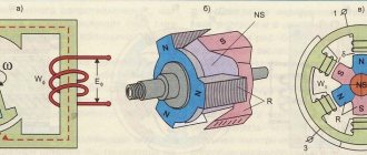
The simplest and very first alternating current generator was developed by physicist Michael Faraday in 1831 and was called the Faraday Disk. The design of the first alternating current generator was very simple. It included the following elements:
- Two different polar magnets “N” and “S”.
- Copper wire frame with sides A, B, C, D.
- Rotation axes N and N1.
The principle of operation of the Faraday alternating current generator was that when the frame rotated, a current with a weak voltage was generated. This happens as follows:
- The wire frame rotates inside a constant magnetic field along the N and N 1 axis.
- When the position of the frame changes from vertical to horizontal, the effect of cutting the magnetic field occurs.
- At such moments, an electromotive force (EMF) arises.
- When passing one half-turn, the emf has a positive potential. Current flows from point A to point B.
- When returning to a vertical position, the EMF changes direction from point C to point D, which means the current potential also changes.
All alternators use a rotating magnetic field. When the position of the copper frame changes, there is also a moment of complete loss of voltage. It occurs when rotating slowly, for example, without a motor. During rapid rotation, the voltage remains unchanged.
Purpose and device
Modern alternators work on the same principle, but use different mechanisms as the driving force. The main purpose of an alternator is to convert some type of energy into electrical current. The energy source can be:
- Powerful flow of water. Such devices are used in hydroelectric power plants. The generator is driven by the flow of water through a narrow channel and the rotation of a turbine. The rotating turbine blades spin the generator shaft, thereby converting mechanical energy into electricity.
- Gas burning. Typical for thermal power plants.
- Using the power of the wind. Such generators are installed in the most windy areas. The main disadvantage is the complete shutdown in calm weather.
- Use of nuclear energy.
- The use of diesel or gasoline engines to rotate stationary or automobile generators.
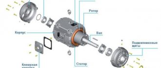
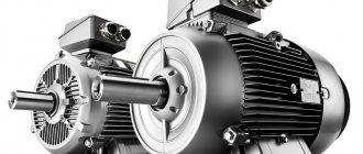
An alternator or alternator consists of the following parts:
- Stator. It is a stationary part of the device. Made from steel sheets that provide resistance to loads. The stator has long slots cut into it to contain the wire winding. This winding removes the generated current.
- Rotor. It is a moving part. Installed directly in the center of the stator. For precise alignment, it is mounted on bearings that are mounted in the front and back covers of the housing. The rotor itself is an electromagnet. It also has grooves and a winding laid in them. It is necessary to excite the stator and generate an electromagnetic field.
- Anchor. A rotor with a winding is mounted on it. It is needed to transmit torque from an engine or turbine.
- Collector. The collector consists of several insulated plates, which are represented by 2 main half rings. Each is connected to the rotor winding. One half with the “+” pole, the other with the minus pole. The generator commutator is needed to rectify and redirect the alternating current.
- Carbon brushes. On some models they are replaced with contact plates. Through the carbon brushes, direct current is supplied from the battery, which is used to pre-excite the rotor winding.
These are the most basic parts that make up the simplest alternator. We examined the design and principle of operation of a modern alternating current generator.
Generators of this type can be synchronous or asynchronous. Both devices are almost identical. The difference between them is as follows. Synchronous and asynchronous models differ in the presence of a winding on the rotor (synchronous) or its absence (asynchronous). The differences also lie in the excitation principle and connection diagram.
Varieties
The internal structure of an alternator depends on its type. Electric machines are divided into 2 main types:
- Synchronous.
- Asynchronous.
There is also a classification according to:
- Method of arousal.
- Number of phases.
- By type of rotor and stator.
Next, a detailed description of all classifications will be given.
Synchronous
The synchronous type alternator has a main feature by which it can be identified at first glance. There is a winding wire on its rotor. It is necessary to stabilize the frequency between the stator and rotor. The EMF in such a device is created due to the intersection of the magnetic pole of the rotor and the stator winding.
A synchronous type alternator is equipped with rotors with several poles, the number of which is always a multiple of 2, for example, 2, 4, 6, 8. The alternator operates according to the following principle:
- After starting, the rotor creates a very weak magnetic field. The magnitude of the EMF increases as the shaft speed increases. For initial excitation, constant voltage from the battery or control unit is used.
- If the generator is powered by an internal combustion engine, the speed must first be stabilized to obtain a stable alternating voltage.
- After setting the required speed, the voltage is stabilized by the automatic regulation unit (AVR). Engine speed greatly affects the frequency of the alternating voltage at the output and its power. The optimal rotation speed is up to 3000 rpm. AVR stabilizes the voltage to this parameter, and in the event of a failure, significantly reduces the voltage. Otherwise, electric pumps can quickly lose power and overheat.
The operation of such a generator is highly dependent on the type of load. The induction type load greatly affects the demagnetization of the armature. This effect results in a large voltage loss.
With capacitive loads, the armature, on the contrary, is magnetized, which significantly increases the output voltage. The circuit of a synchronous type alternating current generator is shown below.
The synchronous alternator has one big advantage. Its output voltage is much higher (3-4 times) the nominal values. An increase is necessary if the device powers electric pumps, appliances and devices that require starting current. Such devices greatly increase the reactive loads on the general network, which a synchronous generator can cope with.
This generator also has disadvantages. The first is the high sensitivity to overload in the circuit. The reaction to the load is a short but quite powerful current on the rotor winding, which appears due to an increase in the current by the control unit itself. As a result, the winding burns out or heats up.
The second disadvantage is sparking. The simplest synchronous type generator has slip rings with brushes installed on the rotor. They are unsafe for use in industrial plants where flammable gases or liquids are present. For such cases, three machine synchronous generators are used. The design and operating principle of this type of alternator is very different. This generator consists of:
- Pre pathogen.
- Pathogen.
- The generator itself.
All these elements are installed on a common shaft. The work is carried out as follows:
- Permanent magnets installed on the shaft excite the winding of the synchronous generator before the exciter. Such a generator does not require a battery or an additional generator for excitation. Its work is based on the phenomenon of magnetic induction, which occurs when a permanent magnet rotates.
- The voltage that it generated is redirected to the exciter, or rather to its stator winding.
- The rotor winding is connected to a three-phase voltage rectifier.
- They are excited by the exciter stator.
Ultimately, the generator produces the nominal required voltage, which is regulated by the AVR unit. All operation of such a device is carried out in one housing, which is completely sealed.
Asynchronous
An asynchronous alternating current generator has a different device. Its rotor has no winding. For this reason, the principle of its operation is very different. During rotation, the rotor of such a generator advances the rotation of the magnetic fields that are created by the stator. The rotors of these devices have 2 types of winding: short-circuited and phase. The operating principle of asynchronous electric generators is as follows:
- A magnetic field is created on the auxiliary winding by the stator.
- After which the field is transmitted to the rotor and forms an EMF on the stator winding.
- The generated voltage is supplied to the control unit.
The main difference is the impossibility of adjusting the voltage at a set speed. Asynchronous generators are highly dependent on drive motors. Any loss of stability leads to a decrease in voltage and frequency of the current.
The advantage of such devices is their low sensitivity to short circuits. Application - power supply of household appliances, welding equipment and electric pumps. When there is a reactive load, the AVR must increase the speed of the drive motor for a short period of time. At the same time, a step-down transformer included in the circuit protects other devices from overvoltage.
Advantages of asynchronous generators
Asynchronous generators are cheaper, easier to maintain, and practically insensitive to short circuits. Since they do not have a brush assembly, they are structurally more reliable than synchronous ones. In addition, they do not have windings on the rotor, and therefore do not need to be cooled (the rotor windings of a synchronous generator need cooling).
However, despite all these advantages, asynchronous power plants are used very rarely for organizing autonomous power supply. The thing is that they cannot withstand short-term overloads that occur when connecting consumers with high inrush currents
As a result, in order to use an asynchronous generator to create a power supply system, you should pay close attention to its power: you must take into account the reactive component of power and select a generator whose power corresponds not only to the total rated power of all planned electricity consumers, but also to the short-term overload that occurs during startup devices that have a reactive load. In addition, asynchronous motors are not very reliable when operating under extreme conditions, and their output voltage stability is worse than that of synchronous ones.
To combat these shortcomings, modern models are equipped with voltage regulators and starting amplifiers. Unfortunately, this adds not only advantages, but also new disadvantages: the design of the generator becomes more complicated and, as a result, reliability decreases (the simpler, the more reliable). But it is simplicity and reliability that are the main advantages of asynchronous generators.
Taking into account all the pros and cons, it is recommended to use synchronous generators to create an autonomous power supply system, despite their higher price and relative complexity of maintenance. Currently, synchronous power plants without a brush assembly are produced. Such models are the most preferable because they are easier to maintain and do not have other disadvantages associated with the presence of a brush assembly.
Phases
The most common and universal types of alternating current generators have 3 independent windings. Such devices are three-phase. Their operating principle is as follows:
- There are 3 windings around the circumference of the power part of the generator stator. They have an offset of 120 degrees.
- Rotation of the rotor excites an EMF of alternating potential in these windings.
- The EMFs have a clock shift of 1 third.
Each winding of such a device is an independent single-phase alternating current generator that is capable of powering a household network.
To reduce the number of conductors that are connected to the generator, one common wire is used. It replaces 3 conductors from receivers. This conductor becomes the neutral. The main features of three-phase generators are as follows:
- The device generates linear and phase voltages.
- With the same load on each phase, no electrical energy flows through the neutral wire.
- When the loads differ, the neutral becomes a current conductor.
- If the generator produces high voltage (more than 380 volts), a step-down transformer is easily connected to its output to transmit electric current to household and industrial networks.
The general diagram of a three-phase generator is presented below.
Three-phase generators can be used for domestic needs. But the connection should be made between several consumers or premises. For individual consumption, a single-phase synchronous type model is suitable. The main thing is to choose a model of suitable power with a small margin.
Excitation
According to the method of excitation, generators are divided into 4 main types. They are as follows:
- Excitement from an outside source. Often this source is a battery or DC generator.
- Self-excited devices. Voltage is supplied to the winding through a rectifier. These types of DC generators are started from a battery, which is connected in parallel to the starter of the internal combustion engine. Also, power can be supplied from the control unit, which is connected to the battery, but significantly increases the current for starting excitation.
- Parallel generator. Or a device consisting of two generators of different power, which are mounted on the same shaft. A low-power device starts from a battery, and the generated voltage is redirected to a more powerful alternator. Both devices are powered by the same drive motor.
- No excitement. Alternating current is produced by an alternator by rotating a permanent magnet. It is enough to simply start the traction motor and the excitation appears due to the magnet. Such devices are the most effective. Does not depend on the presence of a battery. Can be used as mobile stations. For example, three-machine alternators use this operating principle.
Alternating current generators may have a similar design. Often industrial and household models differ only in size and layout. But there is a difference in the principle of excitation and the number of phases. There is also a classification according to the connection diagram of the internal winding.
How to make a generator
Having certain information and practical skills in electrical engineering, it is quite possible to assemble a functional generator with your own hands from an asynchronous motor. First of all, you need to calculate the real, that is, asynchronous speed of the electric motor that will be used as a generator. This operation can be performed using a tachometer.
Next, it is necessary to determine the synchronous frequency of the electric motor, which will be asynchronous for the generator. As already mentioned, here you need to take into account the amount of slip, which is 2-10%. For example, as a result of measurements, a rotation speed of 1450 rpm was obtained, therefore, the required operating frequency of the generator will be 1479-1595 rpm.
The capacitance of the capacitor is selected according to standard comparison tables. In some cases, a standard voltage of 220 V may be required, as in single-phase networks. To solve this problem, a step-down transformer must be included in the circuit.
Thus, self-assembly of the generator is quite feasible. There are several options for using these devices, including a self-powered generator from an asynchronous motor. This unit partially transfers its power to the electric motor used to spin it up. The rest of the energy goes to perform useful work. Due to this, the facility is provided with autonomous power supply for a long time. A homemade generator allows you to save significant money by refusing to purchase a ready-made factory-made electric generator.
Connection diagrams
There are two main schemes for connecting the internal winding. Each with its own characteristics.
- Star. This connection involves connecting 3 winding outputs to a single point. This point is called "zero". The conductors connected to each beginning of the winding are linear and supply current directly to the consumer. The fourth conductor is considered zero. This connection greatly increases the resistance of the network to phase shifts during the occurrence of unbalanced load differences.
- Triangle. The triangle pattern is different from the star pattern. It assumes serial contact of all windings. The first winding is connected at its end to the beginning of the second, and the end of the second to the beginning of the third. The end of the third and the beginning of the first winding are connected to each other. Linear conductors are drawn from each connection point. This scheme implies a balance between phase and line voltages. This circuit is very sensitive to load differences on each phase. When a difference appears, it is necessary to compile a vector diagram and recalculate all parameters.
Each connection diagram also assumes the same wire cross-section. If a large load occurs on one phase, its wire may burn out, which will lead to an asymmetry in the circuit, and in this case, current will flow through the neutral.
Types of asynchronous machines
Homemade generator
Different types of AG may differ in the following performance characteristics:
- The type of rotating part of the generating device - its rotor;
- The number of output or stator windings in the generator (the number of operating phases);
- The connection diagram of the three-phase generator coils - triangle or star, as well as the method of their placement and laying on the stator poles (photo below);
The presence or absence of a separate excitation winding.
In accordance with the first of these characteristics, all known types of AG are equipped with a squirrel-cage or phase-wound rotor. The first of them is made in the form of a one-piece cylindrical structure, consisting of individual pins with two rings closing them (of the “squirrel wheel” type).
The phase rotor, unlike its squirrel-cage counterpart, has an inductive winding made of insulated wire, which ensures the creation of a dynamic electromagnetic field. Due to the peculiarities of its design, such a rotor has a high manufacturing cost and requires specialized maintenance.
The output windings of the stator, like the entire generator, can be single-phase or three-phase, which is determined by the direct purpose of this unit (when a voltage source of 220 or 380 Volts is required). Regarding the first of these designs, everything is quite clear, but the three-phase modification of the AG has one more feature regarding the electrical circuit for switching on the windings.
It is known that to form any three-phase power supply network in electrical engineering, two types of connection of windings are used, shifted in vector representation one relative to the other by 120 degrees. This:
Star switching, when the beginnings of the coils are connected at one point, where a zero wire is formed, and their ends diverge along three power lines (together with the neutral wire, there are four of them, as shown in the photo below);
A “triangle” connection, in which the end of one coil is connected to the beginning of the second, and so on until the chain is completely closed. The second connection option is used in 3-wire power supply lines, since there is no neutral wire in this circuit.
In each AG product, the connection according to one scheme or another is implemented in very specific ways, allowing the wires of all stator windings to be placed between the poles of its core. They are wound in such a way that each section of phase coils A, B and C is offset along the circumference from each other by exactly 120 degrees.
In conclusion of the review of generator devices, let us pay attention to the possibility of manufacturing an AG from an asynchronous motor. Such a prospect appears thanks to the well-known principle of reversibility of the action of electrical machines, according to which the direction of energy conversion can be chosen arbitrarily
Inverter
The inverter alternator generator is a modern and versatile unit that can be used for domestic and industrial needs. The device consists of the following parts:
- ICE running on gasoline or diesel fuel.
- A simple generator that produces alternating current.
- Inverter converter.
- Special connectors for connecting the load.
- Control part.
The peculiarity of such devices is a stable voltage output, the ability to connect to alternating and direct current through separate sockets. Let's look at how this type of generator works.
- The internal combustion engine drives the shaft of a synchronous generator.
- The generated alternating voltage is supplied to a rectifier, which includes a transformer, a diode bridge and a radiator for cooling.
- After the rectifier, which is a converter unit, the current acquires a pulsating voltage with a frequency of up to 20,000 Hz.
- The pulsating current is directed to the filter and passed through the capacitor. As a result, the current levels out and becomes constant with a voltage of 12–20 volts (depending on the type of device).
- The direct current is transmitted to an inverter, which converts it into alternating current with an operating frequency of 50 Hz.
The output of the connector produces a current with a frequency of 50 Hz and a voltage of 220 volts. Inverter generator models have a significant advantage. It consists in the following design nuances:
- AC output with ideal sine wave. This ensures uninterrupted operation of sensitive equipment.
- The filter of the device is assembled on high-voltage capacitors capable of transmitting voltage up to 400 volts.
- A sine wave is formed by a transistor switch. The key repeatedly converts the sine wave due to the paired operation of transistors.
- The device can operate in overload mode for only a few seconds. When the load increases, the protection is triggered and turns off the generator without stopping the internal combustion engine.
At the moment, there are 3 main types of inverter generators:
- Rectangular. Used to power 1–3 low-power electrical appliances.
- Trapezoidal. More powerful. Application - they can power household appliances, but the circuit should not contain devices with high resistance (kettles, stoves, ovens).
- Sinusoidal. The most powerful devices with stable voltage. Can be used to power complex and sensitive equipment and household appliances.
Inverter alternators are compact and quite easy to install and use. They can be connected to a household network through a regular switch, with the main network previously disconnected.
Acoustic noise generator
The principle of operation of the acoustic interference generator is to protect organizations and individuals from eavesdropping on conversations and various types of events. They can be monitored through window glass, walls, ventilation systems, heating pipes, radio microphones, wired microphones and laser devices for capturing the received acoustic information from windows.
Therefore, companies very often use a generator to protect their confidential information, the device and operating principle of which is to tune the device to a given frequency, if it is known, or to a certain range. Then a universal interference is created in the form of a noise signal. For this purpose, the device itself contains a noise generator of the required power.
There are also generators that are in the noise range, thanks to which you can mask the useful sound signal. This kit includes a block that generates noise, as well as its amplification and acoustic emitters. The main disadvantage of using such devices is the interference that appears during negotiations. In order for the device to fully cope with its work, negotiations should be carried out for only 15 minutes.