Before finding out how the VU, ASU, and main switchboards differ, let us remember what the abbreviations given in the title of the article mean.
All these devices share a supply circuit coming from substations or branches of overhead lines from the distribution networks of buildings, structures, houses and other electrical installations.
When planning the installation of an input device, you need to take into account the total power of all available electricity consumers in the house.
Particular attention is paid to houses heated by electric boilers. The boiler's power can account for the lion's share of the energy consumption of the entire house.
Calculation of boiler power is carried out by calculating the required heating radiators, their heat transfer and energy efficiency. Efficient bimetallic and aluminum heating radiators will help reduce the boiler power. Their prices are low, as you can see for yourself by looking at aluminum radiators in Ufa.
VU, ASU and main switchboard
All wording of this article is taken and based on PUE ed. 7, § 7.1.2-7.11.12.
It is important to note that VU, ASU and main switchboards belong to the same group of devices that have the same purpose in electrical circuits; they separate the supply electrical circuit from substations, transformers, VLI branches from the electrical circuit of a house, building, workshop, etc.
The input device on the site is installed on a support.
Hence, the second purpose of these devices is that they divide the areas of responsibility between the service organizations of the power supply networks of the city, town, district and the consumer.
- Applicable to a private house, everything that is located behind the VU, ASU and main switchboard is serviced by the owner.
- Applicable to an apartment, the areas of distribution of responsibility are somewhat shifted towards the end consumer (tenant). The VU, ASU and main switchboard at home are located in the electrical switchboard room, and the resident’s area of responsibility begins after the floor switchboard, or apartment switchboard if it is installed in the apartment.
What is the difference between VU, ASU, main switchboard, answer
All of the above applies to VU, ASU, main switchboard, as a type of electrical devices. And how do they differ? It’s not for nothing that these concepts were introduced.
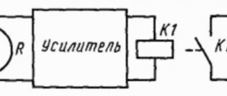
In the input device, there are no devices that can divide and divide the supply circuit into several (at least two) outgoing electrical circuits. Simply, one cable came to the control unit, one cable left the control unit. However, this does not prevent us from producing and assembling input devices with metering devices and surge protection devices.
Important! A mandatory element of the control unit is an electrical breaker, which allows you to disconnect (separate, disconnect) the internal electrical circuit from the supply circuit.
A switch or a powerful circuit breaker can play the “role” of a circuit breaker.
In relation to a private house, the VU can install VLI branches to the house on a pole or on the facade of the house. When using a VU, the electricity consumption meter is mounted separately in a special remote metering panel (RMB).
What is a main switch in electrics - All about electrics
If there are several economically separate consumers in a building, it is recommended that each of them install an independent VU or ASU.
Expert opinion
It-Technology, Electrical power and electronics specialist
Ask questions to the “Specialist for modernization of energy generation systems”
What is a main switchboard (main distribution board) in electrical engineering? Before entering buildings, it is not allowed to install additional cable boxes to separate the service scope of external supply networks and networks inside the building. Ask, I'm in touch!
Lie main switchboard - What is the difference between VU, ASU, main switchboard: the answer is in the standards - SpetsEnergoKabel
- AVR block. It provides connection to the network of backup power sources in case of emergency.
- Accounting panel. Monitors the amount of electricity consumed.
- Elements of protection. Connected for the safety of life and property. They come in several types: fuses, relays, lightning protection and others.
- Measuring instruments. Installed for service purposes to measure current characteristics in the system.
- Signal block. In case of emergency, notifies maintenance personnel.
Types of distribution devices. VRU, main switchboard, ShchR. Differences
Electricity supplied to the facility needs to be properly distributed and accounted for. To do this, the following are installed at the “input”: the main distribution board (MSB) or the input switchgear (IDU).
Installation of the main switchboard is carried out on the line immediately after the substation. The main tasks of the main switchboard are the input and distribution of incoming electricity between consumers and other distribution devices, as well as the protection of outgoing lines. It is possible to install metering panels in the main switchboard panels to control the consumed electricity. The main distribution board consists of incoming and distribution panels, with an operating range of 4000A. The main switchboard may include:
- Automatic transfer unit (ATB), which is used to connect backup power sources to the network (backup line, diesel generator set);
- Accounting panel required to track the amount of electricity consumed;
- Protection devices used to ensure protection of outgoing lines;
- Control and measuring instruments: ammeters and voltmeters;
- A block of light-signal fittings required for visual control of the activation of protection devices.
An input switchgear is a complex of electrical structures that, depending on the units included in it, accounts for and distributes electricity, as well as protects outgoing lines from short circuits and voltage surges.
The design of the input switchgear differs from the main switchboard in its dimensions. The main switchboard is a large cabinet consisting of several panels, and the ASU in most cases consists of one panel.
The composition of the ASU is determined by the specific needs that need to be met at the site.
The ASU may include:
- Input and distribution unit, consisting of input and output switching protection devices;
- The automatic transfer switch (ATS), as in the main switchboard, is used to connect backup power sources to the network (backup line, diesel generator set);
- Accounting panel required to track the amount of electricity consumed;
- Lighting control unit required for manual or automatic control of object lighting;
- PPU panel required for uninterrupted power supply to fire alarm devices at the facility.
Based on the above, it is clear that the main switchboard and ASU are only a formal designation of the functional composition of the devices. The role of the equipment produced by the manufacturer is determined when it is installed on site, therefore the regulatory framework allows the use of an ASU as the main distribution board.
The functions of the main distribution board and the input distribution device are similar, therefore the list of specifically performed tasks is formed by the maintenance personnel of a particular device by adding the necessary blocks and modules.
The only difference in the use of main switchboards and ASUs is that the main switchboard is located higher in the hierarchical chain of the power supply system and the permissible operating current range does not exceed 4000A, while according to GOST R 51732-2001 the maximum value of the rated currents of input devices for ASUs is 630A.
Author of the article: Ivan Trusov – Engineer of the panel equipment assembly department
The main differences between VU, main switchboard and ASU
VU, ASU and main switchboards refer to electrical switchboard devices designed for the safe reception of electrical energy for the purpose of its further distribution. That is, they separate the power supply chain coming from power lines or power substations and the power distribution networks of residential or public buildings, various institutions and any other structures.
What are these 3 devices?
1. VU – input device. 2. ASU – input distribution device. 3. Main switchboard - main distribution board.
They belong to the same type of electrical equipment, since they have the same purpose in electrical circuits - they receive electricity from transformers, electrical substations, and branches of power lines at sites and distribute it to end consumers.
VU, ASU and main switchboards differ in their configuration, additional functions and some other characteristics.
Input devices
Input distribution devices
Main switchboard
You should be aware that energy regulatory authorities may require the installation of meters outside the house, on its façade or on a power pole. It must be mounted in a lockable cabinet with a high level of security.
Main switchboard decoding, device, purpose. What is the difference between an ASU and a main switchboard?
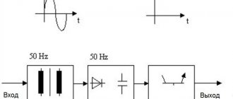
Main distribution boards are designed for full or partial redundant power supply, three-phase alternating current with a rated operating voltage of 380 V and a frequency of 50 Hz in public and industrial buildings.
Contents
hide
1 What is the difference between an ASU and a main switchboard?
2 Typical power supply system with main switchboard on the upper level
3 Schematic diagram of a typical main switchboard main switchboard
What is the difference between an ASU and a main switchboard?
There are many devices in the electrical distribution system. Each of them has its own characteristics and purpose. But certain categories are so closely intertwined that it is difficult to tell the difference. First of all, this concerns electrical switchboard equipment. Here two concepts are often confused - ASU and main switchboard . Even experts cannot always immediately identify the differences, although they probably feel the difference on an intuitive level.
Indeed, the main distribution board ( MSB ) and the input distribution device ( IDU ) are very similar in their design features and functional purpose. Both are designed to receive and distribute electricity. Both are equipped with protection and current characteristics monitoring devices. But still, there are two abbreviations, which means that there is a difference between these concepts. Let's figure out how the ASU from the main switchboard ?
Electrical switchboard equipment has its own hierarchy. And the first input device, of course, is considered the main one. It controls the distribution of electricity between all subsequent panel devices in this hierarchy. So the difference in theoretical concepts is that the main switchboard is at the very top stage, and all subsequent links in this electrical panel circuit are ASU . In practice it looks like this. Immediately after the transformer or boiler room there is a main switchboard . And at the entrances to buildings and on floors, ASUs . But within a specific scheme it may be different: at the entrance to the building there is a main switchboard (main distribution board), and on the floors there is an ASU . That is, these concepts determine only the position of a link in the chain, the level in the hierarchy at which this or that switchboard equipment is located.
The practical side of this issue can be explained even more simply. During manufacture, electrical panel equipment is marked. Along with the serial number and other information, it will almost certainly say “ VRU ”. But when installed at the site as the main electrical panel, this equipment will be marked “ main switchboard ”. And in the project documentation it will appear the same way. That is, it turns out that the ASU is the designation of the product, and the main switchboard is the functional purpose that this product performs.
In fact, the information provided makes it possible to answer the popular question: “what is at the entrance to the building - an ASU or a main switchboard? ". If after the first ASU , which is located at the entrance to the building, there are more ASUs , then a hierarchy arises. Then the first ASU will become the main one and will appear on the diagrams as the main switchboard . If the ASU is the only one, then it is permissible to use both the abbreviation ASU and main switchboard . That is, formally this ASU will be the main one, but at the same time the only one. So in this case, you can emphasize its functional purpose by designating it on the diagram as main switchboard , or simply use the name of the product - ASU .
But these are not all the differences between the ASU and the main switchboard . There is also a formal difference in the permissible current characteristics. It is worth noting here that both concepts are in the PUE (clauses 7.1.3 and 7.1.4) . In addition, these concepts are used in the set of rules (SP 31-110), where there are references to GOSTs. So, if we summarize the information from all this documentation, it will become clear that there are current limitations for the ASU. Thus, the maximum input current should not exceed 630A, and the maximum load on each supply line extending from the ASU should not exceed 250A. At the same time, for switchboard (main distribution board) there are no restrictions on input and output currents. By the way, this confirms the information that the main switchboard is not the name of the product, but only a designation of the ASU as part of the electrical network circuit.
Thus, the concepts of ASU and main switchboard refer to the same type of devices and with the same purpose. But at the same time, these are not synonymous words. The use of one or the other of them will depend on what you want to emphasize - the purpose of the device (that is, the main switchboard as the main ASU ) or its relationship to a certain type of device (a product called ASU ). This is the fundamental difference.
Typical power supply system with main switchboard at the top level
Main distribution board (MSB) - Main switchboard , through which electricity is received and distributed throughout the building or some part of it. As we noted above, an input distribution device or a low voltage switchboard of a substation can serve as a main switchboard. The main switchboard contains emergency automation (for example, circuit breakers or RCD devices), and electricity metering devices (meters).
Main distribution boards the MSB type are manufactured in a multi-cabinet floor-mounted design, designed for the distribution of electrical energy, protection of electrical installations with voltages up to 660 V AC with a frequency of 50, 60 Hz.
The main distribution boards of main switchboards are most often located in the power supply system of a building (structure) at the upper level of power distribution with a voltage of 0.4 kV.
Schematic diagram of a typical main distribution board
Schematic diagram of a typical main distribution board.
Share link:
You might be interested in:
- Concept of "Circuit Breaker"
- Electrical panels - which one to use when and where.
- Electricity meters. Catalog and description
- Surge suppressor - its types and capabilities
Installation of switchgear
The installation process consists of several sequential activities:
- Preparing the foundation.
- Assembly of structures for lighting points of free-standing protective panels and electrical devices.
- Preparation of the internal grounding network and general lighting network of the switchgear.
- Placement of switchgear units. Each cell is installed in a specific place according to the plan. Installation begins with the outermost element. The individual blocks are connected to each other by attaching the side walls to each other.
After completion of installation work, it is mandatory to check the oil level in the tanks of the switches, the correct operation of all main and auxiliary elements and blocking devices. The entire process must be carried out in accordance with the manufacturer’s instructions attached to the equipment.
What kind of lighting do you prefer?
Built-in Chandelier
After making sure that the entire device is assembled correctly (particular attention is paid to ensuring that the cells are not located at an angle), high-voltage cable lines are brought to the terminals on the rear door of the switchgear and secured with end sleeves.
Expert opinion
It-Technology, Electrical power and electronics specialist
Ask questions to the “Specialist for modernization of energy generation systems”
What is a lie in electrics - To help the Electrician The core of the 4-core version is formed by twisting around a central power element; when the number of cores is increased to five, the functions of the central supporting element are assigned to an auxiliary core with a reduced cross-section. Ask, I'm in touch!
main switchboard
Installation is carried out on the consumer side when entering busbars or cables coming from the secondary winding of a 10–6/0.4 kV transformer. The switchboards are made up of separate panels for both single-sided and double-sided floor-mounted service and are divided into inlet panels, sectional panels, and distribution panels. Each panel is a welded metal structure made of bent steel profiles, inside of which the equipment of the main and auxiliary circuits is located.
Production according to modern standards involves the provision of start-up protection equipment, including separate protection devices for each consumer and an electricity metering panel, housed in a unified metal casing. Input and sectional circuit breakers are most often chosen in a withdrawable version to ensure a visible break (4.2.128.PUE. On the low voltage side of the transformer, it is recommended to install a device that provides a visible break). Also, circuit breakers can use motor drives for remote control, additional position contacts, alarm contacts for protection release operation, remote releases for different voltage values to implement an automated transfer switch (ATS) circuit. The use of protective grounding is mandatory. The PE bus in the main switchboard set or a separate main switchgear bus can be used as the main grounding bus.
The bus or cable entry into the input panels can be provided either from above or from below. Outgoing cables for power supply to loads are carried out both through sections in which protection devices are installed, and through special lockable cable sections. Each section can be equipped with additional protective panels and glass doors.
The placement of switchboards is allowed in specially designed premises, closed from outside access, that have a grounding loop. The optimal temperature for work is from +5 to +35 degrees. To prevent electric shock, the main switchboard doors must always be kept closed. The keys to the locks should only be held by specially trained electrical personnel servicing the main switchboard with an electrical safety clearance group of at least 3g. The boards are installed on a specially equipped platform in the room, which has a pit for free supply of supply and outgoing cables.
The nominal operating mode is continuous. This option is equipped with circuit breakers and automatic control systems (instruments) manufactured by ABB (ABB English). To reduce the cost of the design, this specification uses domestically produced housings with a level of protection from external influences - IP31. The housings consist of a rigidly welded frame with guides for fastening corners and mounting panels. The housings have holes for installing the housings in a single row. Housings and individual mounting elements are painted with epoxy polyester powder paint RAL 7032, intended for use indoors without special exposure to external climatic factors (humidity, ultraviolet radiation).
To provide a degree of protection from external influences - IP54, our company uses imported housings from ABB (ABB English) of the TriLine-R Series, which allows for protection against electric shock class 1/2 (grounding/double insulation).
Increase
Increase
ASU: the use of input and distribution devices in residential buildings and in production
- The power cable is connected to the input terminals of the panel.
- A main switch is installed between the input terminals and the distribution busbars.
- Individual consumers are connected to the busbar trunkings through separate circuit breakers. In this case, the ratings of the machines must correspond to the load power.
- When the main switch is turned on, the busbars are energized; with the help of circuit breakers, power can be switched for each consumer separately.
Why is a main distribution board needed?
The main tasks of the main distribution board are the reception and distribution of electricity between individual consumers. Consumers are also protected from excess supply voltage in the event of a network failure, and energy sources and transmission lines are protected in the event of load failures.
TN-C is an outdated system, but it is actively used in old houses. This is a four-wire system consisting of three voltage phases and a combined neutral and working conductors (L1, L2, L3, PEN). In this PEN system, the conductor cannot be split and is delivered to the consumer in this form. It is also worth noting that quite often phase wires are given the names A, B, C.
As a result, with such a power supply system, with a single-phase connection, the consumer is connected with two wires (L, PEN), and with a three-phase connection with four (L1, L2, L3, PEN).
A power cable runs underground from the substation to the house. The cable enters the input box connected to the distribution board:
The risers laid vertically will extend from it. On each floor, floor panels will be connected to the risers, from which the apartments will be supplied with electricity.
Let's look at options for connecting apartments to risers in apartment buildings with a TN-C system. The riser has four wires - three phases and one PEN conductor, designated in the diagram as A, B, C and PEN:
Between phases (A-B, C-B, C-A) the voltage will be 1.73 or more than between any of the phases and the neutral conductor (zero). From here we calculate the voltage between phase and neutral - 380/1.73 = 220 V. Two wires enter each of the apartments - phase and neutral. The current in both of these wires will be exactly the same.
They try to connect the load (in our case, apartments) evenly to different phases. In Figure a), out of six apartments, two are connected to each phase. Uniform connection makes it possible to reduce the neutral conductor current and avoid phase imbalance.
In old houses, combined electrical cabinets were sometimes used instead of floor panels. An example of such a cabinet is shown below:
This cabinet has compartments with separate doors. In one compartment there are signs with apartment numbers, switches and circuit breakers. In another there are meters, in the third there are low-current devices such as telephones, networks of television antennas, twisted pair cables for intercoms, the Internet and other devices.
In such a floor panel, each apartment has one switch and two automatic switches (the first for the general lighting line, and the second for plug sockets). Some versions of electrical cabinets may have a plug socket with a protective contact for connecting various machines (for example, cleaning machines).
Operating principle of the ASU
The arresters are installed behind the introductory machine. Here the connection of phase wires and the PE protective bus takes place. When pulse overloads occur, the arresters are triggered, phase voltage enters the PE bus and the final activation of the ASU protection occurs.
The final distribution of power supply, in accordance with groups of wires, is carried out using circuit breakers with different ratings. Each group of consumers is connected to a separate circuit breaker. As additional protective measures, if necessary, RCDs are installed.
The installation of distribution machines must ensure uniform load distribution between all phases. When calculating machines for each phase, the demand coefficient must be taken into account, which determines the probability of maximum load on electrical networks.
Expert opinion
It-Technology, Electrical power and electronics specialist
Ask questions to the “Specialist for modernization of energy generation systems”
Input devices, distribution boards, distribution points, group boards | PUE 7 | Library | A mandatory element of the control unit is an electrical breaker, which allows you to disconnect, separate, and disconnect the internal electrical circuit from the supply circuit. Ask, I'm in touch!
Equipment
You can order various equipment components from ABB-Electroshield. All parts are reliable and of excellent quality. The product comes standard with:
- ready-made ASU panel, assembled according to technical regulations and in accordance with customer requirements;
- set of keys for built-in locks;
- technical documentation;
- manual;
- documents confirming certification and compliance with GOST requirements.
The cabinets are made of sheet metal with standard dimensions. For individual orders, it is possible to supply equipment of any size. In such exclusive cases, details are discussed in advance and indicated in the technical specifications.
| General characteristics | |
| Rated voltage | 380, 220V |
| Rated current | up to 400A |
| Frequency | 50 Hz |
| Device short-circuit strength (rms value) | 10 kA |
| terms of Use | |
| Degree of protection | IP31 (bottom side IP00) |
| Ambient temperature | from +1 to +40°С |
| Relative humidity | no more than 80% |
| Height above sea level | up to 2000 m |
Composition of the Verkhovna Rada
Kharechko Yu.V. in his book [2] he described in great detail what functional blocks and panels an ASU can consist of. Here are the relevant quotes from his book:
“Input distribution devices consist of functional blocks, which are understood as a set of interconnected equipment installed in the ASU, which ensures the performance of certain functions. In a multi-panel ASU, the functional block can be made in the form of a panel that provides a specific function. »
Input distribution devices can have the following functional blocks [2]:
- input block through which electricity is supplied to the ASU. This functional block contains switching and protective equipment, and also includes part of the ASU volume necessary for placing, fastening and connecting the supply network (circuit) conductors to the equipment;
- an automatic backup power supply unit (ABP), containing monitoring and control equipment for the switching equipment of the input unit, to which backup power supplies are connected;
- an electricity metering unit containing a direct or transformer-connected electricity meter, current transformers and a test adapter box;
- distribution block containing switching and protective equipment of distribution and final electrical circuits. This block also includes part of the ASU volume or panel for placing and connecting conductors;
- an automatic lighting control unit containing switching and protective equipment for the final electrical circuits of general house lighting and control equipment for these circuits.
Multi-panel input and distribution devices consist of panels, which are detachable parts of a multi-panel ASU, made on a single structural basis with other panels and containing corresponding functional blocks.
Input distribution devices may have the following panels [2]:
Main switchboard device
The typical design of the main switchboard is a modular structure consisting of the following panels:
- input panel, usually two pieces;
- one or more linear panels with outgoing consumer power lines;
- a sectional panel that combines two sections of buses when one of the working power inputs is disconnected and the ATS is operating.
In essence, this design is a switchgear with a double sectional busbar system. In normal mode, each bus section is powered from its own working input, while the section switch is turned off. A power failure or emergency shutdown of one of the working inputs triggers the automatic transfer switch (ATS), which turns on the sectional switch. In this case, the load of both bus sections is connected to the power input that remains in operation. When the voltage is restored at the disconnected input, the circuit is automatically returned to its original state.
If necessary, one of the power inputs can be adapted for connection to an autonomous power station. The automation unit in this version should start the generator when the mains voltage disappears. In this case, the possibility of parallel operation of the network and an autonomous voltage source should be completely excluded. The presence of voltage at the working input is monitored constantly and when it is restored, the ATS unit automatically returns the circuit to normal power supply mode.
In circuits with a single power source, a main switchboard with one working input is used.
Main switchboard panels are made in the form of vertical cabinets, which are mounted in a row.
The rules for the construction of electrical installations impose a number of requirements for the installation of main switchboards, including:
- the presence of protection devices, both at the power inputs and on all outgoing lines;
- installation of switching devices on power input lines;
- individual or group control devices on outgoing lines.
The doors of switchgear cabinets, including the main switchboard, must open outward. Access to the busbar can also be provided from the rear side of the cabinet. The front door serves as an operating panel. It may contain:
- panel devices for measuring current and voltage of the electrical network;
- keys for controlling switching devices of power inputs and outgoing lines;
- indicator lamps indicating the position of switching devices.
To ensure clarity and convenience of operational switching, a single-line electrical diagram of the switchgear can be applied to the front panel (door).
Emergency input of backup power (ABP)
This electrical panel is capable of providing emergency power in the event of a main system failure. This type of device can be considered the most common, and it is used in almost every electrical network. If electricity suddenly stops flowing into the system, then the AVR will automatically switch it to the emergency power source.
Most often, two subtypes of AVR shields can be used:
You need to choose a specific product depending on personal preferences, as well as the characteristics of the electrical network.
What is a main switchboard: decoding and how it differs from an ASU
A power cable runs underground from the substation to the house. The cable enters the input box connected to the distribution board:
Expert opinion
It-Technology, Electrical power and electronics specialist
Ask questions to the “Specialist for modernization of energy generation systems”
Why is a main distribution board needed? Some versions of electrical cabinets may have a plug socket with a protective contact for connecting various machines, such as cleaning machines. Ask, I'm in touch!
Price
Before finding out how the VU, ASU, and main switchboards differ, let us remember what the abbreviations given in the title of the article mean.
All these devices share a supply circuit coming from substations or branches of overhead lines from the distribution networks of buildings, structures, houses and other electrical installations.
When planning the installation of an input device, you need to take into account the total power of all available electricity consumers in the house.
Particular attention is paid to houses heated by electric boilers. The boiler's power can account for the lion's share of the energy consumption of the entire house.
Calculation of boiler power is carried out by calculating the required heating radiators, their heat transfer and energy efficiency. Efficient bimetallic and aluminum heating radiators will help reduce the boiler power. Their prices are low, as you can see for yourself by looking at aluminum radiators in Ufa.
7.1.22. A VU or ASU must be installed at the entrance to the building. One or more VU or ASU may be installed in a building.
If there are several economically separate consumers in a building, it is recommended that each of them install an independent VU or ASU.
The ASU is also allowed to supply power to consumers located in other buildings, provided that these consumers are functionally connected.
For air input, surge suppressors must be installed.
7.1.23. Before entering buildings, it is not allowed to install additional cable boxes to separate the service scope of external supply networks and networks inside the building. Such separation must be carried out in the ASU or main switchboard.
7.1.24. VU, ASU, main switchboard must have protection devices on all inputs of supply lines and on all outgoing lines.
7.1.25. Control devices must be installed at the input of supply lines to the VU, ASU, and main switchboards. On outgoing lines, control devices can be installed either on each line, or be common to several lines.
A circuit breaker should be considered as a protection and control device.
7.1.26. Control devices, regardless of their presence at the beginning of the supply line, must be installed at the inputs of the supply lines in retail premises, utilities, administrative premises, etc., as well as in consumer premises that are administratively and economically isolated.
7.1.27. The floor panel must be installed at a distance of no more than 3 m along the length of the electrical wiring from the supply riser, taking into account the requirements of Chapter. 3.1.
7.1.28. VU, ASU, main switchboard, as a rule, should be installed in electrical switchboard rooms accessible only to maintenance personnel. In areas prone to flooding, they should be installed above the flood level.
VU, ASU, main switchboard can be located in rooms allocated in operational dry basements, provided that these rooms are accessible to maintenance personnel and are separated from other rooms by partitions with a fire resistance limit of at least 0.75 hours.
When placing VU, ASU, main switchboards, distribution points and group panels outside electrical switchboard rooms, they must be installed in places convenient and accessible for maintenance, in cabinets with an enclosure protection degree of at least IP31.
The distance from pipelines (water supply, heating, sewerage, internal drains), gas pipelines and gas meters to the installation site must be at least 1 m.
It is not recommended to lay pipelines (plumbing, heating) through electrical rooms.
Pipelines (plumbing, heating), ventilation and other ducts laid through electrical switchboard rooms should not have branches within the room (with the exception of a branch to the heating device of the switchboard room itself), as well as hatches, valves, flanges, valves, etc.
Emergency input of backup power (ABP)
It is important to note that VU, ASU and main switchboards belong to the same group of devices that have the same purpose in electrical circuits; they separate the supply electrical circuit from substations, transformers, VLI branches from the electrical circuit of a house, building, workshop, etc.
Expert opinion
It-Technology, Electrical power and electronics specialist
Ask questions to the “Specialist for modernization of energy generation systems”
Main distribution board (MSB) In the input device, there are no devices that can divide and divide the supply circuit into several at least two outgoing electrical circuits. Ask, I'm in touch!
ASU (input distribution device)
It, unlike the VU, distributes the supply circuit into several branches. In a private house, an ASU can easily replace the main distribution board if there are few branches - for example, they need to be routed to a residential building and a summer kitchen.
But the more buildings there are on the site of a private house, the greater the load on electrical panel equipment of this type, and it is not recommended to overload such a device. The same applies to heating using an electric boiler. Sometimes its power and energy consumption require the installation of powerful electrical panels.
In an apartment building, the ASU usually distributes branches only across floors. Next, floor boards come into play.
Floor (SHE)
This electrical panel is designed for installation in multi-storey residential buildings. It allows you to distribute power to 2-6 apartments.
As a rule, such equipment consists of several main elements:
- subscriber camera
. Protective fuses are installed in it; - recording cameras
. It is used for installing meters; - low current camera
. It installs equipment for the Internet and cable television.
The products are used for metering, receiving and distributing electricity. The equipment also allows you to protect household appliances from voltage surges. Such devices are developed taking into account current requirements for resistance to increased loads and the number of group lines for one apartment.
Expert opinion
It-Technology, Electrical power and electronics specialist
Ask questions to the “Specialist for modernization of energy generation systems”
Input switchgear (IDU) Of course, if the insulation is damaged, a branch circuit can be formed without human intervention, but in this case the RCD will also work and protect the network section from dangerous consequences, such as heating and fire. Ask, I'm in touch!
Access limitation
- Only authorized service personnel may enter the room where the input distribution device is installed.
- A gas pipeline should not pass through this room; other communication networks can be laid, but only without connections. There should be no valves, valves or other shut-off valves here.
- Do not install ASUs in damp and damp rooms, especially in those where there is a high probability of flooding.
- The devices can also be installed on staircases or corridors. True, a cabinet of this type must be locked to prevent unnecessary entry. In this case, all handles of controlled devices must be removable or located inside the box.