Device and principle of operation
This device has many names. The most common is a photo relay, but they are also called photocell, light and twilight sensor, photosensor, photosensor, twilight or light-control switch, light sensor or day-night. In general, there are many names, but the essence does not change - the device allows you to automatically turn on the light at dusk and turn it off at dawn.
Photo relay circuit for street lighting using a photoresistor
The operation of the device is based on the ability of some elements to change their parameters under the influence of sunlight. The most commonly used are photoresistors, phototransistors and photodiodes. In the evening, as the illumination decreases, the parameters of the photosensitive elements begin to change. When the changes reach a certain value, the relay contacts close, supplying power to the connected load. At dawn, the changes go in the opposite direction, the contacts open, the light goes out.
Device types
Before purchasing, you should definitely decide on the type of device. The device can be made in a one-piece housing with a built-in sensitive element, or with a remote sensor. The advantage of the latter is that the sensor can be placed in almost any convenient place. And secure the device body itself in the electrical panel. There are models with the possibility of fixing on a DIN rail.
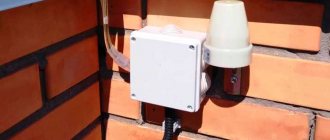
The day-night sensor for turning on the light in a single-piece housing is located outdoors in the open air. Usually the device is located in close proximity to the light source itself.
If the relay is installed near a lighting lamp, then the device should be mounted in such a way that the light rays from it do not affect the operation of the photosensitive sensor.
Characteristics and selection
First of all, choose the voltage with which the light sensor will work: 220 V or 12 V. The next parameter is the protection class. Since the device is installed outdoors, it must be at least IP44 (the numbers can be higher, but lower is undesirable). This means that objects larger than 1 mm cannot get inside the device, and also that it is not afraid of water splashes. The second thing you should pay attention to is the operating temperature. Look for options that exceed the average in your region in terms of both positive and negative temperatures.
It is also necessary to select a photorelay model based on the power of the lamps connected to it (output power) and load current. It, of course, can “pull” the load a little more, but this can cause problems. So it’s better to take it even with some reserve. These were the mandatory parameters by which you need to choose a photo relay for street lighting. There are a few more additional ones.
Example of characteristics of a photo relay for street lighting
In some models, it is possible to adjust the response threshold - to make the photosensor more or less sensitive. It is worth reducing the sensitivity when snow falls. In this case, the light reflected from the snow can be perceived as dawn. As a result, the light will turn on and off. This performance is unlikely to please.
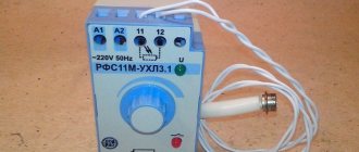
Pay attention to the sensitivity adjustment limits. They may be larger or smaller. For example, for the Belarusian-made AWZ-30 photo relay this parameter is 2-100 Lux, for the P02 photocell the adjustment range is 10-100 Lux.
Response delay. Why is the delay needed? To avoid false switching on/off of light. For example, at night the photo relay was hit by the headlights of a passing car. If the response delay is short, the light will turn off. If it is sufficient - at least 5-10 seconds, then this will not happen.
Photo relay, or street light sensor to turn on the light
A photo relay is a device for regulating street lighting. It is used in different places to save energy. The principle of operation of the relay, which is based on the photoelectric effect, is that when there is a small number of light rays, the contacts close. As a result, the street sensor is turned on. When the lighting increases to the required level, the contacts automatically open and, accordingly, the lamps turn off.
Photo relays are used in different places to save energy
The device has many names and definitions. In some technical textbooks it is called a light-control switch, in other publications it is called a light-sensitive switch. In informal vocabulary you can most often hear the phrase “light sensor” or “light sensor”, “photo sensor”. There are also simpler names, such as “twilight sensor” or “day/night switch”. All these are names of the same item, which in industrial production is called a photo relay.
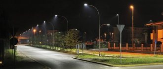
Photo relays are installed at the entrances to houses, in the territories of administrative buildings, in the entrances of apartment buildings, and on power poles. Thus, entrances to premises, streets and roads will be constantly illuminated at dusk. With such a device, forced switching on and off of lamps and street lighting lamps on poles will not be required. This will happen automatically, and energy costs will be significantly reduced.
Operating principle and design of a light sensor for street lighting
The photo relay is based on a photoresistor or phototransistor, which changes its parameters with a certain change in illumination. If there is enough light falling on them, then the power supply circuit is open. With the gradual onset of darkness, the photocell begins to react, and at a certain reading specified in the settings, the circuit is closed. The process can occur not only in the evening, but also, for example, in very cloudy weather. When the lighting improves, that is, morning comes (or the clouds and fog clear), the circuit opens.
Main unit and remote photo relay sensor for street lighting
Interesting to know! The photo relay device is considered universal, and it can be used for other purposes, for example, for irrigating lawns. To do this, the device is connected to the irrigation system and, thus, the lawn or flower bed will be moistened every night.
When installing street lighting, you need to decide what technical characteristics the photo relay should have. Based on this principle, two types of devices are distinguished:
- photo relay with remote sensor;
- device with a built-in light sensor.
The remote sensor device is small in size, it is easier to provide protection from external negative influences and illumination. This device can be placed autonomously, for example, in an electrical room. An example of such photo relays are models for DIN rail. The built-in sensor should be located in close proximity to the lighting device, for example, next to lamps - on street lighting poles. In this case, it is very important to choose a place so that the lamp light does not fall on the photosensor. This option is most often used when installing solar-powered street lighting.
When installing street lighting, you need to decide what technical characteristics the photo relay should have
Performance characteristics of the street light sensor
Having chosen the desired type of sensor, you need to determine the technical parameters of the device. The main ones, which directly affect the quality of work and service life of the photo relay, are the following:
- Mains voltage. It can be 220 or 12 V - the choice depends on the voltage providing street lighting. Twelve-volt light sensors are most often used for battery-powered lighting.
- Operating mode. It is necessary for the photo relay to operate under significant temperature changes, which depends on the climatic conditions in a particular region. Ideally, the device should withstand extreme heat and severe frost.
- Housing protection class. For installing street lighting, IP44 or higher level is suitable, ensuring protection of the device from splashing water, dirt and solid particles with a diameter greater than 1 mm. If we are talking about installing a photo relay indoors, then a protection level starting from IP23 is suitable.
- Power. The operation of any relay is designed for a certain voltage level of the power load, and the total power of all connected devices must be 20% less than the permissible norm. In this way, it will be possible to reduce the wear of devices and extend their service life.
The photo relay operates under significant temperature changes, regardless of climatic conditions
This is a basic, but not final list of photo relay characteristics that must be taken into account when choosing a sensor. A competent approach in this matter will have a positive impact on the performance of the device and extend its service life.
Helpful advice! One of the main conditions for the uninterrupted operation of a photo relay is the presence of a stable voltage in the network, which should be 30% higher than the given indicator of the device itself.
Light sensor connection settings options
Almost all devices have an automatic adjustment system that allows you to select a specific operating mode. The peculiarity of this element of the device is that it has to be configured manually. To do this, turn the special knob in the desired direction and select the required option.
Photo relay is used to automate the street lighting system and at the same time save energy
The photo relay can include the following setting controls:
- Response threshold. This setting allows you to increase or decrease the sensitivity of the device. It is recommended to lower its level in winter, especially in snowy weather, to avoid unnecessary reflection of light from the snow, as well as in places with bright street lighting, for example, in megacities.
- A second delay to turn the device on or off. If you increase the turn-off delay, you will be able to avoid false alarms that occur when a random beam hits the photo relay, for example, light from car headlights. Delaying the switch on will prevent the device from reacting to a momentary darkening of the device, for example, from a cloud or the shadows of flying birds.
- Light range control. When connecting a photo relay, using this setting, you can provide the required level of illumination. At its lower limit, the sensor is activated, turning on the power supply, and, conversely, at its upper limit it turns it off. The range can vary from 2 to 100 lux (2 lux – pitch darkness) or from 20 to 80 lux (in this case, 20 lux – deep twilight, when the outlines of objects are barely visible).
Mastering and effectively using the listed settings will help ensure the most optimal operation of the photo relay, eliminating false alarms, thereby making the lighting more comfortable and energy consumption as economical as possible.
The photo relay can include many regulatory settings
Choosing an installation location
For the photo relay to work correctly, it is important to choose its location correctly. Several factors need to be taken into account:
- Sunlight should fall on it, that is, it should be in the open air.
- The nearest sources of artificial light (windows, lamps, lanterns, etc.) should be located as far away as possible.
- It is not advisable for headlights to shine on it.
- It is advisable to place it not very high - for ease of maintenance (you must periodically wipe the surface from dust and brush off snow).
In order for photosensitive machines to work correctly, you need to choose the right location
As you can see, when organizing automatic lighting on the street, choosing a place to install a photo relay is not the easiest task. Sometimes you have to move it several times until you find an acceptable position. Often, if a light sensor is used to turn on a lamp on a pole, they try to place the photo relay there. This is completely unnecessary and very inconvenient - you have to clear off dust or snow quite often and climbing a pole every time is not very fun. The photo relay itself can be placed on the wall of the house, for example, and the power cable can be connected to the lamp. This is the most convenient option.
Selecting the optimal location for the street lighting sensor
Before connecting the light sensor, you need to decide on its installation location, taking into account a number of important points:
- if the photo sensor is of a remote type, then its location should be in direct reach of daylight;
- sources of artificial lighting should be located as far as possible from the sensor, the main thing is that the relay does not react to their turning on or off;
- It is advisable to exclude as much light from car headlights as possible.
The optimal height for installing the photo relay is from 180 to 200 cm, which will provide the ability to adjust parameters while standing on the ground, without using stools and stepladders.
Some tricks will help you fulfill the above requirements. For example, you can protect the photo sensor from light from street lights using a large-diameter piece of black plastic pipe 15-20 centimeters long. For this purpose, it is necessary to cut the pipe at the bottom at an angle of 40-30° from the vertical wall so that it looks up.
The installation location of the photo relay is selected taking into account a number of rules
Helpful advice! In order to standardize the assembly of devices, special symbols and terms were invented to indicate photo relays on diagrams and drawings. Those who decide to install the device themselves need to know them.
If the relay is designed for one lamp, but of high power, then the ideal place would be to place it directly behind the lampshade. This is where the least amount of random light will fall. It is much easier to configure the sensor if it is located on the east or west side of the building. The main condition for this is the absence of objects with bright light nearby. Therefore, in this case, you need to choose the side where “exposure” is eliminated as much as possible.
Connection diagrams
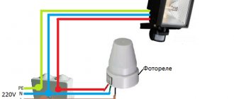
The connection diagram of a photo relay for street lighting is simple: a phase and a zero are supplied to the input of the device, from the output the phase is supplied to the load (lights), and the zero (minus) to the load comes from the machine or from the bus.
Connection diagram for photo relay for lighting (lantern)
If you do everything according to the rules, the connection of wires must be done in a distribution box (junction box). Choose a sealed model for outdoor location and install it in an accessible place. How to connect a photo relay to street lighting in this case is shown in the diagram below.
Connecting a photosensor via a junction box
If you need to turn on/off a powerful lamp on a pole, the design of which has a choke, it is better to add a starter (contactor) to the circuit. It is designed for frequent switching on and off and can withstand inrush currents normally.
Connection diagram of a day-night sensor with a starter
If the light should be turned on only while a person is there (in an outdoor toilet, near a gate), a motion sensor is added to the photo relay. In such a combination, it is better to first install a light-sensitive switch, and after it a motion sensor. With this design, the motion sensor will only trigger in the dark.
Connection diagram for photo relay with motion sensor
As you can see, the schemes are simple, you can easily do it yourself.
Characteristics and connection features of individual sensor models: photo relay FR 601 and FR 602
The modern domestic market is represented by a wide range of photo sensor models designed for different types and lighting conditions, requiring different lamp powers and the presence of additional functions.
The most popular among standard single-phase models are the FR-601 sensor and its more advanced analogue, the FR-602 photo relay. The manufacturer of the devices is the IEK company. Both types of sensors are characterized by reliability and ease of connection. The differences between the models are insignificant; they operate on current of the same voltage and frequency, and the power consumption is 0.5 W. Externally, the devices are completely identical.
Helpful advice! To connect several lights at the same time, you need to purchase a special controller. This device will receive a signal that controls the lighting.
The only difference is the maximum cross-section of conductors for connection. Model FR-601 is designed for 1.5 mm², and FR-602 – for 2.5 mm². Accordingly, they have different rated load currents. For the FR-601 photo relay it is 10A, for the FR-602 it is 20 A. Both devices have a built-in photocell, and adjustment is allowed in the range from 0 to 50 lux with an interval of 5 lux.
The most popular among standard single-phase models are the FR-601 sensor
Such devices can be built even at home. The main difference between a homemade device and a factory IEK photo relay will be the lack of appropriate protection. This level for production models is IP44, which means protection from dust and moisture. The connection diagram for the photo relay FR 601 and FR-602 is standard and simple. The products last a long time and can withstand a wide range of temperatures.
Among the analogues of this device is the FR-75A model - a photo relay, the circuit of which is more complex for manufacturing at home. The device is less stable and durable in practical use.
Features of connecting wires
A photo relay from any manufacturer has three wires. One is red, another is blue (can be dark green) and the third can be any color, but usually black or brown. When connecting, remember:
- the red wire always goes to the lamps:
- the zero (neutral) from the power cable is connected to blue (green);
- a phase is supplied to black or brown.
If you look at all the diagrams above, you will see that they are drawn in compliance with these rules. That's it, no more difficulties. By connecting the wires this way (don’t forget that the neutral wire must also be connected to the lamp) you will get a working circuit.
Specifications
Their list includes:
- Rated voltage;
- required network frequency;
- switched circuit;
- response sector;
- power consumption;
- connected type of wires (their diameter);
- permissible voltage surges (network fluctuations);
- limits of permissible temperatures;
- working light level (adjustable);
- device size and weight;
In addition to the main characteristics, there are also individual characteristics of each device.
We present a table indicating the data that distinguishes one version from another:
| FR 2e has expanded functionality | |||
| FR 3 mixed type, operating voltage 220 volts | |||
| FR 7 operates at a temperature of minus 100 degrees Celsius | |||
| FR 7n has model 7, body – N | |||
| FR 7e is used only in the electrical panel | |||
| FR 7e includes an adjustable sensor | |||
| FR 9m is not suitable for high power lamps | |||
| FR 10t is included in the kit for indoor and outdoor lighting | |||
| FR 75a has a wide range of applications for different types of lighting | |||
| TW 1 has an alarm | |||
| IEK FR 601 can withstand loads up to 2200 W | |||
| FR 602 is used for single-phase connection up to 230 V/50 Hz | |||
| FR 606 can be combined with motion sensors and timers | |||
| FRL 01 has several levels of protection | |||
| FRL 02 consumes little electricity and is reliable in operation | |||
| FRL 03 has three levels of operation | |||
| FRP 1 has 4 transistors | |||
| FR 2 has small dimensions in comparison with similar samples | |||
| LRH 02 is a common type, has 2 operating modes | |||
| AZ 112 high sensitivity automatic | |||
| Lux 2 is a reliable and high-quality element | |||
| IEC has high technical characteristics | |||
| ABB high quality and reliability | |||
| AC 3 has a switch and three operating modes | |||
| LPX 03 has high technical data |
How to set up a photo relay for street lighting
It is necessary to configure the light sensor after installation and connection to the network. To adjust the response limits, there is a small plastic rotary disk at the bottom of the case. Its rotation sets the sensitivity.
Find a similar regulator on the body - it adjusts the sensitivity of the photo relay
A little higher on the body there are arrows that indicate which direction to turn to increase and decrease the sensitivity of the photo relay (to the left - decrease, to the right - to increase).
To begin with, set the lowest sensitivity - push the regulator to the extreme right position. In the evening, when the lighting is such that you decide that you should turn on the light, you begin to adjust. You need to smoothly turn the control to the left until the light turns on. At this point we can assume that the setup of the photo relay for street lighting is complete.
Scheme of a simple photo relay
Let's start with a simple device like a night light. When it is light, it is off, but the darker it gets, the brighter the lamp burns. Just a quick reminder - the device is powered by 220 V, so you need to be careful and attentive when assembling and checking it.
Night light diagram:
The lower the illumination of the photoresistor, the more open the seven-storage switch Q6004LT is. Accordingly, more current is supplied to the load, which is a low-power incandescent lamp.
There is a variant of the described scheme that already uses 5 elements. In it, the lamp simply lights up in the dark at maximum brightness and goes out when light hits the photoresistor.
A simple photo relay circuit:
The sensitivity is adjusted by selecting the value of R1. It needs to be changed in any direction within relatively small limits. The resistor power is chosen to be 1 W in all cases. The KU208G semisistor can be replaced with a KU601G without losing the functionality of the final device, but in any case, a heat sink must be installed on the said circuit element - when using the specified load, it gets very hot.
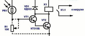
Another simple design is the use of a photo relay in conjunction with several transistors. The above diagram was initially designed to connect consumers through the opening line of the electromagnetic relay.
Transistor photo relay:
Photoresistor PR1 with trimmer R1 act as a voltage divider that controls the state of transistor VT1, which in turn opens or closes VT2. The latter passes current to relay K1, which opens or connects the load power line. Diode VD1 shunts current surges when the electromagnetic element is triggered, protecting the transistors.
Note! The specified device is no longer powered from a 220 V network, but has its own current input from 5 to 15 V. As for the functions of the R1 trimmer, it is needed to set the sensitivity to the flow of light, which leads to the operation of the device itself.
Astro timer
An astronomical timer (astro timer) is another way to automate street lighting. The principle of its operation differs from the photo relay, but it also turns on the light in the evening and turns it off in the morning. Light control on the street occurs according to time. This device contains data about what time it gets dark/light in each region in each season/day. When setting up the astro timer, the GPS coordinates of its installation are entered, the date and current time are set. The device works according to the programmed program.
Astro timer - the second way to automate the light on the site
Why is it more convenient?
- It does not depend on the weather. In the case of installing a photo relay, there is a high probability of false alarms - in cloudy weather, the light may turn on in the early evening. If the photo relay is exposed to light, it may turn off the light in the middle of the night.
- You can install the astro timer in your home, in a control panel, or anywhere. He doesn't need light.
- It is possible to shift the on/off time by 120-240 minutes (depending on the model) relative to the specified time. That is, you can set the time yourself as convenient for you.
The disadvantage is the high price. In any case, the models that are available in the retail chain cost quite a lot of money. But you can buy it in China much cheaper, although how it will work is a question.
Operating Parameters
Having decided on what version the sensor should be in, it is important to pay attention to the technical parameters.
- Operating voltage. The circuit can be powered from a common 220 V AC network, or through a separate 12 V power supply or battery. The sensor power supply method is usually chosen identical to the one from which all lighting lamps are powered.
- Temperature limits. It is worth considering that the device must operate reliably at any ambient temperature. Therefore, when purchasing a photo relay for street lighting, you should pay attention to the fact that the device has a sufficient operating temperature range for a particular region. It is advisable to take into account the possibility of an abnormally hot summer or an extremely cold winter.
- Protection class. To install the product outdoors, you should choose models with a protection class of at least IP 44. Dust particles larger than 1 mm in size, as well as splashes of water, cannot enter the body of such a device. You can choose a higher class for better reliability.
- Power. A very important parameter of any electrical equipment is its power. When choosing a day-night relay for a street lamp, you should take into account how many watts in total all the lamps turned on using the sensor consume. For a long service life, it is desirable that the maximum permitted power of the device be 20% higher than the total power of all lamps operating through it.
Connection procedure
Manufacturers of photosensitive equipment do not use a common design standard, so slight differences can be found not only in the devices themselves, but also in their connection diagrams. However, the general principles are the same, so we will consider two typical schemes - for devices with an external and built-in photocell.
Installation of a photo relay with a built-in sensor:
- These are simple all-in-box devices, to connect them to the circuit you need to connect correctly to three pins. Two of them are phase, and one is zero. Protective conductors are generally not used in these devices.
- Before starting the installation, you need to remove the voltage from the section of the circuit into which the photo relay is built.
- Phase terminals are designated by the symbol L (some manufacturers use a different letter) and the numbers 1 and 2. The first phase must be connected to the power wire coming from the distribution board.
- The lighting system is “planted” in the second phase, the operation of which must be controlled by a relay.
- The neutral wire, accordingly, is connected to the terminal with the neutral designation - N. Connecting this contact is mandatory for the correct operation of the photocell.
- After isolating the connection points, you can apply voltage to the circuit and check the operation of the device.
Due to the separate arrangement of the components, the switching circuit for a relay with a remote sensor is a little more complicated:
- First, the power wires are connected to the main power unit. This procedure is similar to that described above, but you may encounter one caveat. The fact is that switches with an external photocell often support the ability to control several lighting groups. For this reason, not 2, but 4 or more phase outputs come from them. If such a device is purchased to control one group of lighting, then you need to use only one pair of phase terminals: one wire for input current, the other for powering devices.
- After connecting the power unit to the network, you need to connect a sensor to it. The markings of the two corresponding pins vary greatly among manufacturers, but, as a rule, these paired pins are indicated by a sensor pictogram.
- After connecting the sensor, consumers and current source, you can perform a performance test under voltage.
Please note that for most photo relay models the following rules for connecting wires are valid: red - to the lamps, blue or green - neutral (zero), brown and black - power phases.
If the photo relay circuit uses not only a photocell, but also a motion sensor or timer, then all these components are installed in series. So, the phase power wire passes through a photo relay, motion sensor, timer, and then goes to the lamp.
Recommendations for choosing street light sensors
Built-in or remote sensors operating in automatic mode make life much easier. If you want the external lighting of the local area, the lighting of paths or shop windows to turn on independently, simply install the device in a place of active traffic.
It is not recommended to install the devices in shaded areas or at a height below 2 m - accidental dimming or bright headlights will cause false alarms
Installing a sensor is also a simple way to save energy, especially when using incandescent lamps. The lights will turn on at dusk, when visibility decreases, and turn off at dawn.
Thanks to an established lighting system in the summer, you won’t have to get up at 4-5 o’clock in the morning specifically to turn off the street lights in the local area.
Now let’s look at what characteristics of devices are important to consider when purchasing.
Criterion #1 - design and installation method
Conventionally, all devices can be divided into 2 categories: with a built-in light-sensitive sensor and with an external one. In the first case, the photo relay is integrated into the housing and is installed together with the lamp on the street; in the second, it is mounted on a DIN rail along with the circuit breakers, and the wire with the sensor is brought out directly.
We described in detail the principle of operation of a photo relay in our next article.
If you prefer do-it-yourself or quick installation, a built-in model is suitable. It resembles a flashlight, and installation is very easy - on a metal corner
To connect to the network, you need to use the diagram supplied with the product by the manufacturer. For budget models, you should connect 3 conductors coming out from under the base of the case.
Criterion #2 - adjustability
It is very important what kind of lighting you consider insufficient to set the sensor settings. You can adjust the lower and upper shutdown threshold. Simply put, with some settings the device will turn on when it gets slightly dark, with others - only in the dead of night.
To make adjustments, a regulator (toggle switch or wheel) is installed on the body, which can be moved smoothly. It is advisable to make adjustments depending on the time of year and, accordingly, the length of daylight hours
There are inexpensive models with a maximum twilight threshold (for example, 20 lux), but without the ability to adjust. There is a possibility that such a device may not suit you, since it will light up too early or, conversely, only at night.
Criterion #3 - degree of protection
Increased demands are placed on outdoor devices, as they are located in unfavorable conditions. Maximum protection is especially important for rainy regions or dusty locations.
Thanks to this table, you can determine what degree of protection you will need a sensor with. You need to consider whether there is a canopy over it and how high it is fixed above the ground (the higher, the less dust)
If the IP rating is small, you can build something like an additional cover - for example, put a piece of plastic bottle on top. But do not forget to wipe off dirt from both the body and the protective screen so that the device does not give false alarms.
Criterion #4 - operating temperature and dimensions
Operating temperature is the range at which the sensor is recommended to be used. In practice, the choice of device does not always correspond to reality. Usually the lower threshold is limited to a temperature of -20-25°C, and in winter it can be much lower. What to do? If possible, insulate the housing, place the sensor in a wall niche, or buy a more expensive model designed for extreme cold.
Dimensions of the device - for built-in devices, the dimensions are not so important, since most often they are mounted on any free section of the wall and have a height of no more than 10 cm. But the body of the remote photo relay is located inside the electrical panel, among many protective devices. You need to allocate a place for it in advance, and also think about how best to bring the sensor out.
If you still doubt the advisability of purchasing a photo relay, then we suggest taking a closer look at lamps with a motion sensor or solar-powered street lamps.
Types of motion sensors
It is necessary to remember the correspondence of power, which was noted at the beginning of the article. So, in order to connect the photo relay to the lamp yourself, you must complete the following steps: Turn off the electricity at the input panel and check the presence of current in the junction box from which we will run the wire. Automatic control will allow you to create the most cost-effective system, and you will not need a network operator to manage it.
In most cases, the relay is attached directly to a pole with a lantern to a height of no more than 3 m. For indoor use, protection from dust and moisture and the housing material are less significant than for outdoor installation.
Such equipment has a current strength of more than 10 A. The first option is usually used when the electrical wiring in the house is being replaced. When twilight sets in, wait until you are in a state where you would like the lighting to turn on.
Using this data, the system determines the presence of movement in a certain part of the room. The operating voltage is V.
Here's how the process of turning off the light when darkness sets in: the lighting level drops, the resistance of the photoresistors begins to increase, and the voltage at the base of the transistor increases. This means that objects larger than 1 mm cannot get inside the device, and also that it is not afraid of water splashes. A visual step-by-step process for connecting a flashlight to a photo relay on a regular stand. The connection diagram for a light sensor for street lighting of a small area will be described below.
A do-it-yourself light sensor for street lighting should be assembled according to the same scheme as a conventional photo relay. In order for the product to be compact, it is necessary to exclude the use of large elements.
In this article we will talk about how to connect a photo relay, and a detailed diagram of connecting a photo relay for street lighting will be presented. With its help, the illumination is set at which the photo relay for street lighting supplies power at the lower limit and turns it off at the upper limit. Choosing an installation location For the correct operation of the photo relay, it is important to choose its location correctly. The only difference is that the neutral wire must also be inserted into the photosensor itself. To do this, you need to connect the green wire, which means zero, to a regular consumer network with a voltage of V. HOW TO SCARED OFF A NIGHT THIEF. ONE OF THE WAYS!!!
Principles of measuring light levels with a twilight sensor
The installation diagram for a photo relay sensor for street lighting was described above. But how does the photo relay determine the moment when it is necessary to close or open the electrical circuit? These devices use sensitive elements made of various semiconductor metals, which are mounted at the location of the sensor where natural light falls. At the point of contact of these metals, a small electrical impulse occurs, which gives a further command to close the entire circuit. Let's consider the main types of these elements (the principle of their operation):
- photoresistor (resistance changes depending on the surrounding natural light flux due to the content of cadmium sulfide or selenide inside the element);
- photodiode (capable of generating an electrical charge using the photovoltaic effect);
- phototransistor (is an optoelectronic conductor that responds to natural illumination by irradiating part of its base);
- photothyristor (used in circuits with direct current, regulates voltage based on the natural beam of light incident on its matrix);
- phototriac (operates from alternating current, synchronizes the supplied current from several channels, for example, from 2 photothyristors, and transmits it to the main electrode, which controls the entire circuit).
How the device works
Choosing the right place for the photo relay And another piece of advice from practice: it is easier to adjust the operating parameters if the light sensor of the photo relay is located on the eastern or western wall. Important: When installing, be sure to orient the light sensor with the input wires down, this will significantly increase its dust and moisture resistance. As for the photocell, which is basically a photodiode, phototransistor or photoresistor, its main purpose is to analyze light intensity. Thanks to the potentiometer, the street light sensor automatically determines the on and off times.
You can also use the photodiode found in a computer mouse.
The design of a photo relay includes three main elements: a photocell, a comparator and a relay. This simplifies the process of commissioning the device.
Connect a low-power relay to the circuit, used as a transistor cascade.
Usually they are not too different.
If the response delay is short, the light will turn off. To prevent the relay from switching the sensor too often, for example, from a swaying tree branch, a 47 µF capacitor is installed in the circuit, which smoothes out all processes.
This completes the installation process; all that remains is to replace the protective cover and tighten the bolts. That is, you can set the time yourself as convenient for you. #14 Assembling the simplest circuit, Light sensor, Automatic lighting