A magnetic starter is a device responsible for the uninterrupted operation of equipment that meets standard requirements. It is used to distribute the supply voltage and control the operation of connected loads.
Most often, power is supplied to electric motors through it. And through it the engine is reversed and stopped. All these manipulations will be made possible by the correct connection diagram for the magnetic starter, which you can assemble yourself.
In this article we will talk about the design and operating principles of a magnetic starter, and also understand the intricacies of connecting the device.
Modular contactor: connection and installation, device
Practical advice: When purchasing a modular contactor, you need to inquire about the availability of a certificate of conformity for it, as well as the offered guarantees. Well-known brands always provide warranties for their products .
Expert opinion
It-Technology, Electrical power and electronics specialist
Ask questions to the “Specialist for modernization of energy generation systems”
Connection diagram for 220V contactor, description, application, parameters. What is a contactor for and how to connect it? Many people believe that famous manufacturers monitor product quality better and, accordingly, deserve more trust. Ask, I'm in touch!
How to connect a contactor?
Contactors are switching equipment for controlling mainly three-phase motors. For contactors, the main task is to turn on, turn off and reverse at a distance, which is determined by the specific location of the motors. But motors are not the only electrical consumers with which contactors can be used. Any other types of loads can also be switched remotely using these switches. In principle, they are a structural variation of a magnetic starter.
Basic device
The contactor consists of several units:
- Energy.
- Powerful.
- Switching.
The energy node ensures the formation of an electromagnetic field sufficient to obtain a certain unidirectional force. This field appears as a consequence of the flow of electric current through a coil with a core. Its shape is either U- or W-shaped, depending on the design of this switching product.
The magnetic field lines are most concentrated near the core, and therefore the power unit is designed so that the impact on it from the energy unit is maximized. For a more uniform force that occurs when alternating current flows through the coil, a short-circuited turn is made in it. It plays the role of a damper that prevents contact chatter at a frequency of 50 Hz. If the coil is powered by direct current, a dielectric spacer is placed on its core to prevent magnetized parts from sticking together.
The power unit contains a movable spring-loaded ferromagnetic element - an armature, which is attracted to the stationary coil core, transmitting force to the switching unit. It contains contacts. Their number may vary, depending on the design of the contactor. To control electric motors in three-phase networks, there are three or four contacts - identical in their characteristics. But there may also be additional low-power contacts used to control auxiliary elements of the circuit.
- The location of additional contacts determines the difference between a contactor and a magnetic starter. They are located in a group with the main contacts, and not on the side, as in a magnetic starter.
In addition to the contacts, the switching block contains chambers for extinguishing the electric arc.
How does it work
The power unit spring keeps the contacts open. When the force from the armature becomes sufficient to overcome the elastic forces of the spring, the power and switching units begin to move. The anchor deforms the spring, simultaneously dragging the contacts along with it, and they close. The armature is in contact with the core of the coil and is held by its electromagnetic field. After de-energizing the coil, the spring returns to its original state along with the armature and contacts.
For normal operation of the contactor, a voltage of a strictly defined value is supplied to the terminals of its coil. For contactors used in electrical networks, these are 220 and 380 V. Therefore, it is necessary to correctly connect the coil to a three-phase network. If the rated voltage of the contactor is 220 V, the coil is connected to any of the phases (to phase voltage). And if 380 V - between any two phases (to line voltage).
A push-button station is used to control the contactor. It consists of two buttons:
- normally open for switching on;
- normally closed to turn off.
The contactor connection diagram combines an additional contact and a push-button station. The button designed to turn on and the additional contact are connected in parallel, and through them voltage is supplied to the coil. Pressing the power button closes the coil circuit. The anchor moves and closes all contacts. The additional contact makes the power button unnecessary to power the coil. Therefore, after the contactor has tripped, it can be released.
The state of the contactor will not change. It will remain on. But the contacts of the shutdown button are closed until the button is pressed. We press on it - the coil's power circuit is broken. The magnetic field disappears, and the contacts open under the influence of the contactor spring. The coil's power supply circuit is also broken at an additional contact. Therefore, the shutdown button can be released, and this will not affect the state of the contactor in any way.
Connection diagrams for a magnetic starter with a 220 V coil
Before we move on to the diagrams, let’s figure out what and how these devices can be connected. Most often, two buttons are required - “start” and “stop”. They can be made in separate housings, or they can be a single housing. This is the so-called push-button post.
Buttons can be in the same housing or in different ones
Everything is clear with individual buttons - they have two contacts. One receives power, the other leaves it. There are two groups of contacts in the post - two for each button: two for start, two for stop, each group on its own side. There is also usually a ground terminal. Nothing complicated either.
Connecting a starter with a 220 V coil to the network
Actually, there are many options for connecting contactors; we will describe a few. The diagram for connecting a magnetic starter to a single-phase network is simpler, so let's start with it - it will be easier to understand further.
Power, in this case 220 V, is supplied to the coil terminals, which are designated A1 and A2. Both of these contacts are located at the top of the case (see photo).
This is where you can supply power to the coil.
If you connect a cord with a plug to these contacts (as in the photo), the device will be in operation after the plug is inserted into the socket. In this case, any voltage can be applied to the power contacts L1, L2, L3, and it can be removed when the starter is triggered from contacts T1, T2 and T3, respectively. For example, a constant voltage from a battery can be supplied to the inputs L1 and L2, which will power some device that will need to be connected to the outputs T1 and T2.
Connecting a contactor with a 220 V coil
When connecting single-phase power to the coil, it does not matter which output is supplied with zero and which with phase. You can switch the wires
Even most often, the phase is supplied to A2, since for convenience this contact is located on the bottom side of the housing. And in some cases it is more convenient to use it and connect the “zero” to A1.
But, as you understand, this scheme for connecting a magnetic starter is not particularly convenient - you can also supply conductors directly from the power source by building in a regular switch. But there are much more interesting options. For example, you can supply power to the coil through a time relay or a light sensor, and connect the street lighting power line to the contacts. In this case, the phase is connected to contact L1, and zero can be taken by connecting to the corresponding coil output connector (in the photo above it is A2).
Diagram with start and stop buttons
Magnetic starters are most often installed to turn on an electric motor. It is more convenient to work in this mode if there are “start” and “stop” buttons. They are connected in series to the phase supply circuit to the output of the magnetic coil. In this case, the diagram looks like the figure below
note that
Switching diagram of a magnetic starter with buttons
But with this method of switching on, the starter will operate only as long as the “start” button is held down, and this is not what is required for long-term operation of the engine. Therefore, a so-called self-catching circuit is added to the circuit. It is implemented using auxiliary contacts on the starter NO 13 and NO 14, which are connected in parallel with the start button.
Connection diagram for a magnetic starter with a 220 V coil and a self-retaining circuit
In this case, after the START button returns to its original state, power continues to flow through these closed contacts, since the magnet has already been attracted. And power is supplied until the circuit is broken by pressing the “stop” key or by triggering a thermal relay, if there is one in the circuit.
Power for the motor or any other load (phase from 220 V) is supplied to any of the contacts marked with the letter L, and is removed from the contact marked T located underneath it.
It is shown in detail in what order it is better to connect the wires in the following video. The whole difference is that not two separate buttons are used, but a push-button post or push-button station. Instead of a voltmeter, you can connect a motor, pump, lighting, or any device that operates on a 220 V network.
Features of the circuits
From the illustrations showing how the contactor is constructed, it is obvious that it does not have any protection. But it is unacceptable to operate circuits that do not have at least fuses. Especially in the presence of unwelded and unsoldered connections of wires and cables. In connections made using hardware, when the contacts are loosened, the contact resistance increases like an avalanche. And, as a consequence of this, heating of the current-carrying conductor, melting of the insulation, short circuit and, possibly, ignition of something.
Such contact deterioration can occur in any electrical product in which the wire is pressed with a screw. If this product is a circuit breaker that has thermal protection, it will trip due to heat in the frame. However, a contactor or magnetic starter does not have such protection. Therefore, regular periodic inspection and fuses are the only countermeasures against such malfunctions.
Subtleties of connecting a 220 V device
Regardless of how it is decided to connect the magnetic starter, the project must have two circuits - power and signal. Voltage is supplied through the first, and the operation of the equipment is controlled through the second.
Features of the power circuit
Power for the MP is connected through contacts, usually designated by the symbols A1 and A2. They receive a voltage of 220 V, if the coil itself is designed for such voltage.
It is more convenient to connect the “phase” to A2, although there is no fundamental difference in the connection. The power source is connected to the contacts located lower on the housing.
The type of voltage does not matter, the main thing is that the rating does not go beyond 220 V.
Through a magnetic starter equipped with a 220 V coil, it is possible to supply voltage from a diesel and wind generator, battery, and other sources. It is removed from terminals T1, T2, T3
The disadvantage of this connection option is that to turn it on or off you need to manipulate the plug. The circuit can be improved by installing an automatic machine in front of the MP. It is used to turn the power on and off.
Changing the control circuit
These changes do not affect the power circuit; in this case, only the control circuit is upgraded. The whole scheme as a whole undergoes minor changes.
When the keys are in the same casing, the assembly is called a “button station.” Each of them has a pair of inputs and a pair of outputs. The “Start” button has normally open (NC) terminals, while the one directly opposite has normally closed (NC) terminals.
The keys are built in series in front of the MP. The first one is “Start”, followed by “Stop”. The contacts of the magnetic starter are manipulated by means of a control pulse.
Its source is the pressed start button, which opens the path for supplying voltage to the control coil. “Start” does not have to be kept on.
It is supported by the principle of self-capture. It consists in the fact that additional self-locking contacts are connected in parallel to the “Start” button. They supply voltage to the coil.
After they are closed, the coil is self-energized. A break in this circuit results in the MP being turned off.
The stop button is usually red. The start button can have not only the inscription “Start”, but also “Forward” and “Back”. Most often it is green, although it can also be black.
Connection to 3-phase network
It is possible to connect 3-phase power through an MP coil operating from 220 V. Typically, the circuit is used with an asynchronous motor. The signal circuit does not change.
One phase and “zero” are connected to the corresponding contacts. The phase conductor is laid through the start and switch off keys. A jumper is placed on contacts NO13, NO14 between the closed and open contacts
The power circuit has differences, but not very significant. Three phases are supplied to the inputs indicated on the plan as L1, L2, L3. The three-phase load is connected to T1, T2, T3.
Input into the thermal relay circuit
In the gap between the magnetic starter and the asynchronous electric motor, a thermal relay is connected in series. The choice is made depending on the type of motor.
The thermal relay will protect the electric motor from malfunctions and emergency situations that may arise when one of the phases fails
Connect the relay to the terminal with the magnetic starter. The current in it passes to the motor in series, simultaneously heating the relay. The top of the relay is equipped with additional contacts integrated with the coil.
Relay heaters are designed to accommodate the maximum amount of current flowing through them. They do this so that when the engine is in danger due to overheating, the relay can turn off the starter.
Re: Connecting a motor without a starter
With frequent switching on and off of a loaded machine, premature wear of the power contacts is possible. Carbon deposits form on it, which increases the contact resistance and, as a result, heats up. Starters, by the way, can also sin with this. Older people should remember Soviet times, when electricians on duty at production often had to change contacts on starters due to burnt contacts - fortunately they were replaceable and replaceable within the limits of their size.
Acshel Posts: 46 Joined: 02 Feb 2016, 18:32
Re: Connecting a motor without a starter
By itself! - PML, PME, PMA if I'm not confusing anything. Although in fact it wasn’t that long ago, and they’re probably still changing it here and there...)
Vadim84 Messages: 61 Registered: Jan 19, 2016, 5:59 pm
additional information
There is no fundamental difference between a contactor and a magnetic starter, and this has already been mentioned above. Their task is also the same - remotely turning on and off the load. The circuits in which these types of switches are used are also identical. When describing circuits, some specific terms are used. We will dwell on them further for completeness of information.
"Self-pickup." This means that the power button in the push-button station is connected in parallel with a contact that is closed by the action of the coil, the power of which begins immediately when the said button is pressed. Self-retaining, although not mentioned earlier, is present in each of the schemes shown above.
"Reverse". The reverse circuit involves obtaining from two contactors or magnetic starters the switching of the motor windings to change the rotation of its rotor to the opposite. An example of such a scheme is given below.
Overview of options
In manual mode, activation is carried out from a push-button station. The start button opens the contact to close, and the stop button works to open. The connection diagram for a self-retaining magnetic starter is as follows:
Let's consider the operation of the on and off circuits of a magnetic contactor. A push-button station of two buttons, when you press START, the phase comes from the network through the STOP contacts, the circuit is assembled, the starter retracts and closes the contacts, including the additional NO, which is parallel to the START button. Now, if you release it, the magnetic starter continues to operate until the voltage disappears or the thermal relay P for motor protection is triggered. When STOP is pressed, the circuit is broken, the contactor returns to its original position and the contacts open. Depending on the purpose, the power supply to the coil can be 220V (phase and zero) or 380V (two phases), the operating principle of the control circuits does not change. Switching on a three-phase electric motor with a thermal relay through a push-button station looks like this:
In the end it looks something like this, in the picture:
If you want to connect a three-phase motor through a magnetic starter with a 220-volt coil, you need to make the switch according to the following wiring diagram:
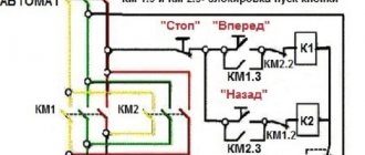
Using three buttons on the control panel, you can organize the reverse rotation of the electric motor.
If you look closely, you can see that it consists of two elements of the previous diagram. When you press START, the KM1 contactor turns on, closing the NO KM1 contacts, becoming self-retaining, and opening the NC KM1, excluding the possibility of turning on the KM2 contactor. When you press the STOP button, the chain is disassembled. Another interesting element of the three-phase reversible connection circuit is the power section.
On the KM2 contactor, phases L1 are replaced by L3, and L3 by L1, thus changing the direction of rotation of the electric motor. In principle, this circuitry for controlling three-phase and single-phase loads completely covers household needs and is easy to understand. You can also connect additional automation elements, protection, limiters. They all need to be considered separately for each specific device.
Using the above diagram for connecting a magnetic starter, you can organize the opening of a garage door by introducing additional limit switches into the circuit, using NC contacts in series with NC KM1 and NC KM2, limiting the movement of the mechanism.
Connection diagram for abb esb 20-20 contactor via switch
A contactor, which is controlled by a switch, is used to turn energy-consuming equipment on and off. The most obvious example of how such a combination works is the system for turning on and off all the lights in an apartment from one place.
Such a main switch is usually installed at the exit from the apartment. When leaving home, you can use it to turn off all the lights at once. The reverse procedure awaits you when you return; by pressing the switch key, you turn on all the lights that were working before leaving.
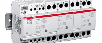
To implement this logic of lighting operation, you will need a contactor and a switch. ABB ESB 20-20 modular contactor , paired with a conventional single-key light switch.
Before we look at the connection diagram in detail, a few words about this contactor model.
Each symbol in the name of ABB contactors has a specific meaning.
Typically the marking looks like this:
ABB series xx-yz
Amperage voltage , where
ABB is the name of the manufacturer
series – Equipment series XX – current for which the contacts are designed Y – Number of contacts to be closed (normally open/open NO) Z – Number of contacts to be opened (normally closed/closed NC)
amperage – Rated current, voltage – Operating voltage
We talked in detail about how a contactor is designated on single-line diagrams HERE.
The ABB 20-20 modular contactor we selected:
– belongs to the ESB series, considered “household”;
– The rated current for which the contacts are designed is 20A;
– contains 2 independent closed contacts, which, until a signal is received, are normally open;
This logic of contactor operation (normally open contacts) when controlling a switch is most preferable in most cases and allows you to operate a load of up to 40A (2 pairs of contacts of 20A each).
It is more convenient to use a modular contactor with a 220V AC coil (the coil voltage is indicated on the device body, in our case it is 250 Volts “
The contactor is modular.
ABB modular contactors are divided into two series: ESB and EN. The difference is that ESB contactors are controlled only by supplying or turning off voltage and are designed for currents of 20, 24, 40 and 63A, while EN contactors have additional manual control (on/off) and are designed for currents up to 40A.
Contactors have two types of contacts . Some contacts are power contacts that open or close power circuits, and others are control contacts for the contactor itself, i.e. directly give a command to close/open the power ones.
Control contacts A1-A2 are designated the same on all contactors. It is to them that voltage must be applied or removed so that the power contacts open or close.
Power contacts that turn on or off the load connected to the contactor are always in pairs 1-2, 3-4, 5-6, 7-8 , etc.
the ABB EN40-40N contactor it follows that this modular contactor is designed for a rated current of 40A and has four NO (normally open) contacts . It is also stated that the contactor coil is designed for 230V AC or DC.
To protect the contactor control coil, it is correct to install a circuit breaker in its circuit, etc. The power consumed by the coil is negligible, so it is better to take the rating of the machine no more than 1A.
The ESB 20A contactor occupies 1 module, 24A - 2 modules, 40 and 63A - 3 modules each on a DIN rail.
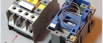
Contactors are also available with manual control, or more precisely with combined control. Those. You can use the switch to turn the modular contactor on and off with your hands by moving the lever. The photo below shows an ABB EN-40-4NO contactor with manual control.
Contactors, as well as other modular devices of the leading series ABB, Legrand, Schneider Electric, Hager, can have an additional contact . Just keep in mind that these are “not entirely full-fledged” contacts; they have a rated current of only up to 6A .
Below is an example of an additional contact for a Legrand contactor. The auxiliary contact actually has two contacts, one NC and one NO.
Connecting the modular contactor and the auxiliary contact is easy. The connection diagram between the devices is shown on the additional contact itself. It is important that the hole in the contactor and the “lever” of the auxiliary contact align exactly.
Modular contactor ABB (ABB) ESB-20-11 220V 20A AC
The transferred funds will be returned to your bank account within 5 to 30 business days. The period depends on the bank that issued your bank card.
Expert opinion
It-Technology, Electrical power and electronics specialist
Ask questions to the “Specialist for modernization of energy generation systems”
Selection of ABB ESB modular contactor by load | Modular contactor normally closed ABB in Moscow | Modular contactors ABB catalog Additionally, the RCBO protects equipment from overloads and short circuits, which compares favorably with conventional grounding. Ask, I'm in touch!
Connection diagram for ABB esb 20-20 contactor for 220V via a switch
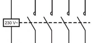
Below is a visual diagram of the operation of a contactor through a switch.
It is assembled as follows:
“Phase” is supplied to the switch, which, having passed through it, returns to the control terminal A2 of the contactor. “Zero” is permanently connected to the second terminal A1. A phase is also connected to terminal 1 of the contactor, and a conductor going to the load is connected to terminal 2.
The principle of operation is simple: as soon as you press the switch key, electric current flows to the contactor terminal A1, and therefore to the coil. Next, according to the principle of an electromagnet, the internal contacts, which are normally open, are closed, and the electric current flows to consumers - electrical equipment. As soon as you click the switch key again, the electrical circuit is broken and the contacts inside the modular contactor open, de-energizing the equipment. It's quite simple.
To the second terminals 3-4, you can connect another load up to 20A, for example, a second group of lamps. Accordingly, in total, the contactor will withstand about 9 kW (current - 40A) power.
If you assemble a similar circuit without using a contactor , simply passing the phase of the common power cable of all lighting groups through a switch, problems immediately arise:
– You are limited by the maximum current that the switch can withstand, rarely more than 10A.
– Since the switch does not have any contact protection systems, it would quickly fail, the contact pads would burn out or the housing would melt. A fire may occur.
As you can see, there is nothing complicated about connecting a contactor through a switch. And now, understanding the logic of operation and the order of connection, you will be able to independently develop and implement interesting, and most importantly useful equipment control schemes using contactors.
What is a modular contactor and what is it for?
According to its functional purpose, the modular contactor KM belongs to the switching equipment for remote control of powerful loads operating at direct or alternating current. They break current circuits in several places at once, and this differs from electromagnetic relays, which break the circuit at only one point.
Quite often, modular contactors work in conjunction with auxiliary devices - set-top boxes, thermal relays, blocking devices and other modular devices. As a result of such combinations, equipment is obtained that has special properties and is capable of performing specified functions. So, when installing a delay module, you get a contactor with a delay function, and a thermal overload relay transfers the contactor to the category of a magnetic starter.
With the help of auxiliary elements, the capabilities of the main devices are significantly expanded, their performance characteristics are improved, and installation is simplified.
At their core, contactor devices are considered modified versions of a starter, which additionally contains a thermal relay and a contact group for starting the electric motor. Low voltage electromagnetic starters, reversible and non-reversible. The first option includes two identical contactors, with the same rated current. It has a mechanical or electrical interlock that prevents the main contacts from closing at the same time.
The protective functions in these devices are performed by electrothermal current relays and other similar devices. Low power electrical contactor, used as an intermediate relay. It is designed for low-current circuits and has a large number of switchings. Using this device, it is possible to connect many additional sections and control their on/off.
Contactors and starters - what's the difference?
Both contactors and starters are designed to close/open contacts in electrical circuits, usually power ones. Both devices are assembled on the basis of an electromagnet and can operate in DC and AC circuits of different powers - from 10 V to 440 V DC and up to 600 V AC. Have:
- a certain number of working (power) contacts through which voltage is supplied to the connected load;
- a number of auxiliary contacts - for organizing signal circuits.
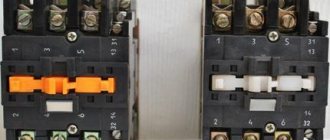
There is one more design feature: the starters are produced in a plastic case, with only the contact pads exposed outside. Contactors, in most cases, do not have a housing, therefore they must be installed in protective housings or boxes that will protect against accidental contact with live parts, as well as from rain and dust.
Apparently because the “filling” and functions of both devices are almost the same, in many price lists the starters are called “small contactors”.
Design and principle of operation
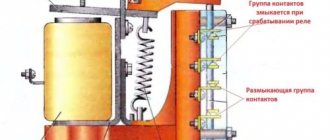
A standard contactor design includes several basic parts. The device consists of a housing (1), a control coil output terminal (2), a power contact terminal (3), a fixed magnetic core (4), a moving part - a core (5), a control coil (6), a short-circuited magnetic circuit ring (7), fixed and moving contacts (8 and 9), on-off indicator lever (10).
The coil is the main element that creates the magnetic current. If it is also used as a throttle, then with its help a driving force is generated that ensures the operation of the devices. The tension of the contacts is fixed using a contact spring. During docking, the moving and fixed contacts are connected to each other. They are constantly in motion and perform certain actions. Fixed contacts are fixed to the body, and movable contacts are connected to the core.
The contactor works as follows:
- After applying voltage to the control coil, the armature is attracted to the core. As a result, the contact group closes or opens, in accordance with the initial position of a particular contact.
- After turning off the power, all actions occur in the reverse order. The electric arc that occurs at the moment of opening is extinguished using an arc extinguishing system.
- After the voltage supply is stopped, the electromagnetic field disappears and ceases to hold the armature or core.
- The return spring moves the contacts to their original position, completely opening the circuit. Thus, the modular contactor performs its main work during periods of supply and shutdown of voltage.
Connecting an electric motor according to a star and delta circuit
The main methods of connecting three-phase electric motors to the network are used: “star connection” and “delta connection”.
When connecting a three-phase electric motor with a star, the ends of its stator windings are connected together, the connection occurs at one point, and three-phase voltage is supplied to the beginning of the windings (Figure 1).
When connecting a three-phase electric motor using a “triangle” connection diagram, the stator windings of the electric motor are connected in series in such a way that the end of one winding is connected to the beginning of the next and so on (Figure 2).
Terminal blocks of electric motors and winding connection diagrams:
Without going into the technical and detailed theoretical foundations of electrical engineering, it must be said that electric motors with windings connected by a star operate smoother and softer than electric motors with windings connected in a triangle, it should be noted that when the windings are connected by a star, the electric motor cannot develop full power. When the windings are connected according to a delta circuit, the electric motor operates at full rated power (which is 1.5 times more power than when connected by a star), but at the same time it has very high starting currents.
In this regard, it is advisable (especially for electric motors with higher power) to connect according to the star-delta circuit; Initially, the launch is carried out according to the star circuit, after which (when the electric motor has “gained speed”), automatic switching occurs according to the triangle circuit.
Control circuit:
Connecting the supply voltage through the NC (normally closed) contact of the time relay K1 and the NC contact K2, in the starter coil circuit K3.
After turning on the starter K3, with its normally closed contacts it opens the circuits of the coil of the starter K2 with contacts K3 (blocking accidental switching) and closes contact K3 in the power circuit of the coil of the magnetic starter K1, which is combined with the contacts of the time relay.
When the starter K1 is turned on, the contacts K1 close in the coil circuit of the magnetic starter K1 and at the same time the time relay turns on, the contact of the time relay K1 opens in the coil circuit of the starter K3, and the time relay contact K1 closes in the coil circuit of the starter K2.
Switching off the winding of the starter K3, contact K3 closes in the coil circuit of the magnetic starter K2. After turning on the starter K2, it opens its contacts K2 in the circuit of the power coil of the starter K3.
Control circuit
Three-phase voltage is supplied to the beginning of the windings U1, V1 and W1 through the power contacts of the magnetic starter K1. When the magnetic starter K3 is triggered using its contacts K3, a short circuit occurs, connecting the ends of the windings U2, V2 and W2 to each other; the motor windings are connected by a star.
After some time, the time relay, combined with the starter K1, is activated, turning off the magnetic starter K3 and simultaneously turning on K2, the power contacts of K2 are closed and voltage is supplied to the ends of the motor windings U2, V2 and W2. Thus, the electric motor is switched on in a triangle pattern.
Classification of contactor devices
There are different types of contactors, differing from each other in various respects. Among them, the following parameters can be distinguished.
First of all, they are classified according to their purpose. This includes the following types and categories:
- Devices for remote switching. Most of them operate under manual operator control using buttons or switches. At the right time, a signal is given and the device is activated. In another method, several contactors are connected into a common automated power system that uses electronic circuitry to issue commands. In case of an emergency, a protection system is provided that opens the contacts.
- Switching on powerful electrical equipment using low-current lines. The question arises, why is a contactor needed in such cases? Wouldn't it be better to use a traditional button? This, of course, can be done, but then you will need very massive and bulky equipment, and the switching process itself will require significant effort. The same goes for turning it off. Therefore, compact low-current devices are used for these purposes, allowing for high-frequency on-off cycles. Thus, a weak current is supplied to the coil, and only then the powerful electric motor is started.
How to choose the correct modular contactor rating
As follows from the previous section, the number of switching cycles directly depends on the type of load and vice versa. In normal mode AC1 - in the field of domestic use, where the network of the building (apartment) will be turned off and then only in an emergency, for example - a dangerous voltage surge, imbalance or phase failure - the number of on/off operations. – minimal. So everything is quite simple - we select the rating of the circuit breaker in front of the ESB contactor - either greater than or equal to it. The principle here is the same as with an RCD, voltage relay or automatic phase switch - a more powerful contactor is better than one equal to the value of the circuit breaker. The optimal current reserve is 20-30%.
If you plan an industrial AC-3 mode - with electric drives and electric motors and, at the same time, complete with a timer (cyclic on/off mode) - choose a 40A model only if the load is in the range of 10-12 A per phase (one pole). If this indicator is or is planned to be exceeded, choose a more powerful model - ESB 63-40 at 63A.
Connection diagrams for consumers and modular contactors
In accordance with the type of electrical equipment used, in each case an individual connection diagram for the modular contactor is provided. The most widespread is the standard version, which uses only one device, as well as reversible circuits and with the connection of single-phase consumers. Each of them should be considered in more detail.
The most popular scheme is connecting a three-phase electric motor through a modular contactor KM (Fig. 1). The usual START and STOP buttons are used for control. Overload protection is provided using a thermal relay. In case of short circuits, the electrical circuit is equipped with an automatic switch.
Another circuit is reversible (Fig. 2), used when connecting a modular contactor to an electric motor so that the reverse function appears. It is constantly needed in various lifting mechanisms, machines and other equipment. In this case, another switching device is connected. It is involved in changing the locations of two phases, which also leads to a change in the direction of rotation of the shaft. This circuit is also supplemented with protective equipment - a thermal relay and a circuit breaker.
The main purpose of contactors in the third circuit is to work with single-phase consumers. As a rule, these are lighting systems, electric pumps and other equipment operating with a single phase.
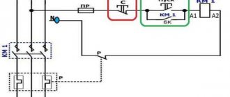
Connection diagram for a 220 V magnetic starter
Here, the current is supplied to the magnetic coil KM 1 through a thermal relay and terminals connected in a chain of buttons SB2 for turning on - “start” and SB1 for stopping - “stop”. When we press “start”, electric current flows to the coil. At the same time, the starter core attracts the armature, resulting in the closure of the moving power contacts, after which voltage is supplied to the load. When “start” is released, the circuit does not open, since the KM1 block contact with closed magnetic contacts is connected parallel to this button. Thanks to this, phase voltage L3 is supplied to the coil. When you press “stop,” the power is turned off, the moving contacts return to their original position, which leads to de-energization of the load. The same processes occur when the thermal relay P operates - a break in the zero N supplying the coil is ensured.
Tags: automatic, sconce, varistor, type, switch, generator, engine, house, , grounding, replacement, star, like, contactor, , magnet, magnetic, marking, installation, power, load, voltage, nominal, lighting, connection , principle, wire, project, start, , work, size, relay, switch, row, light, connection, resistance, means, circuit, ten, type, current, triangle, three-phase, , phase, photo, shield, electric motor, electrical panel , anchor