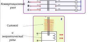
How is power supplied (and disconnected) to electrical installations or power lines (of course, we are talking about local wiring, not high-voltage lines)? Using various types of switching devices. These can be plug devices (plug-socket), manual or automatic safety switches, electronic control circuits. It is practical and safe to use remote switching devices such as a modular contactor.
Let’s immediately dispel the false opinion: such switches (switches) are not strictly industrial devices. AC contactors are widely used in everyday life. And not only in private houses, but also in apartments.
Design and principle of operation of the contactor
Based on the name, this is a group of contacts designed to connect electrical lines. The main application is a modular contactor that switches power lines. If in a regular switch (even an automatic protective one), closing and opening occurs manually, AC contactors are controlled remotely.
Let's consider the circuit of a simple contactor, without interlocks and protective modules.
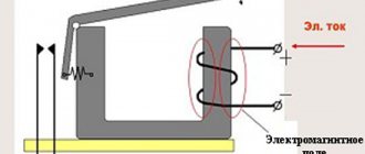
For those who are more or less familiar with electrical engineering, it is not difficult to understand the principle of operation. The basis of the power group is the contacts indicated in the diagram by the letters “L” and “T”. Depending on the design, the system may simultaneously include one, two, or more pairs of contacts. In order for the connecting conductor strip to press against the fixed contacts, force is required. In conventional switches, this is a mechanical device driven by the operator. Our circuit is triggered by an electromagnet. When control voltage is applied to coil A1-A2, the solenoid is retracted and the power (operating) contacts are closed.
To ensure reliable and safe opening, a return spring is provided.
After removing power from the control winding, the return spring instantly removes the contact strip from the power terminals.
What is inside
Despite the apparent complexity and cumbersomeness of the design, the element base is simple:
- contact group made of copper (brass) alloys, designed for a certain resource;
- “T” shaped contact strip directly connected to the electromagnet solenoid;
- an electromagnet coil made for a specific contactor model;
- dielectric housing, which performs not only protective, but also load-bearing functions;
- arc extinguishing elements that are installed in the switching mechanisms of electrical installations with high current consumption.
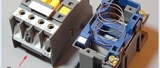
In fact, the design is not much different from a conventional relay. There are also normally closed, normally open, and switching circuits (in which both types of contact groups are present). At the same time, according to the technical requirements of GOST, the modular contactor must have only one rest position (the state of the contact group in the absence of external control pressure).
When mechanical action is applied to a conductive strip (or group of strips), one or more contact pairs are closed (opened).
Thus, with the help of direct or remote influence, it is possible to control the power of electrical installations or power lines.
Parameters and technical indicators
The main indicators of electromagnetic contactors include the following:
- Number of main contacts. For direct current devices their number is 1-2, for alternating current - 2-5.
- Indicator of the current rating in the power circuit.
- The value of the maximum switching capacity of the device. Indicates the maximum current that can be switched off by the contactor without loss of performance.
- The rated voltage of the power circuit is no more than 660 V, the control circuit is 12, 24, 48, 110 and 220 V. Based on these data, we select the desired device.
- Resistance to switching wear of starters, up to 2 million cycles. The device must withstand the specified number of switching operations under the influence of current in the power circuit, and be suitable for subsequent use.
- Resistance to mechanical wear, discussed above. Indicates the number of operations without current in the power circuit. For contactors, this figure is 10-20 million cycles; the required device is selected based on it.
- Duration of own switching time. This is the time period from the moment of switching on (the command is given) until the moment when the contacts are completely closed.
- Duration of own shutdown time. It starts from the moment the shutdown command is given until the electric arc is completely extinguished.
- The value of current characteristics on additional contacts, their number and type. According to their functions, they can be of closing or breaking action.
Purpose of contactors
These devices can be divided according to their main characteristics, although the scope of application is virtually unlimited.
Types of contactors by purpose
- Remote switching devices (switching off, switching). When operating a complex of electrical installations, it becomes necessary to implement a certain power supply algorithm. Manual control: button, switch. The operator gives a signal at the right moment, the AC contactors are activated, switching the power according to a given operating pattern. For example, by pressing one button you can start an entire plant: conveyor, machines, lighting, ventilation system. By connecting many contactors in a certain way, it is possible to automate the power system on the control circuit (in this case, starting commands are given manually). In automatic mode, the command is given using an electronic circuit. The program controls production cycles at the right time, starting and stopping electrical installations. At the same time, any linear contactor can be equipped with a protection function: for example, a limit switch or thermal relay. When certain emergency conditions are created, the power to the coil is cut off and the operating contacts are opened.
- Switching on a powerful electrical installation using a low-current line, or again with a button (switch). A typical example is an electric motor starter.
It would seem, what does a modular contactor have to do with it: what is it for if you can use a button or a switch? Indeed, power can be supplied to the electrical installation directly using the contacts of the button. However, for a reliable connection of a powerful consumer, the contact group and the closing mechanism must be massive, and great force must be applied when turning on. The same force must be used to de-energize. This is not always convenient, especially in an emergency. Therefore, the device with which the operator directly works is compact, it is designed for low current (the consumption of the contactor coil is small), and a small force is required to activate it, especially on the off button. And the linear contactor itself can be quite large, and it operates instantly. Another reason why power separation of control and power lines is used is the high frequency of on and off cycles. For example, electric vehicles. The driver presses the accelerator pedal up to a thousand times per shift. If you equip the lever itself with power contacts, it will be inconvenient to use. Therefore, the pedal only supplies a weak current to the coil, and the line contactor starts the powerful electric motor.
Many of you, being near the driver's cabin, have heard regular loud clicks when pressing the pedal. This is exactly how a line contactor works.
Various drive types
- Electromagnetic is the main type and the most common. We discussed the principle of its operation in detail at the beginning of the article. Unless you can focus on the holding mechanism of the working coil. Most push-button (magnetic) starters do not have a locking button. That is, after the operator removes his finger, the power to the electromagnet should disappear. The design of most starters takes this point into account. There is a contact group on the end plate pusher that closes the solenoid circuit. While the entire electrical installation is working, there is power on the coil. If the voltage drops for a short time (emergency situation, or the disconnect button is pressed), all circuits are broken and the switch is turned on again. This adds safety during operation of the mechanism. After an uncontrolled power restoration, the electrical installation will not start until the operator decides to turn it on.
Information:
- When applying direct voltage (ordinary switch), dangerous situations sometimes arose:
the power is lost (line failure), the electrical installation is de-energized;
- the working day is over, the switch remains closed (the machine is not working, everyone has forgotten about the accident);
- power on the line is restored, machines, heating elements, etc. begin to work in the deserted workshop.
The use of contactors eliminates such situations.
The operating principle is the same, only the high pressure pulse acts as a control command. Such devices are widely used on railway locomotives, or other installations where pneumatics are present.
Specifications
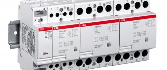
Each individual modular contactor has its own operating parameters, so we suggest considering the most popular models from Schneider Electric, IEK, ABB and others.
Photos - dimensions and characteristics of models KM, MT and MF
Schneider Electric iCT16A 1NO 1 NC:
| Current strength, A | 6–16 |
| frequency Hz | 50/60 |
| Performance | 100 cycles per shift |
| Switched device power, W | 2,1 |
| Polarity | 2 poles |
| Approximate wear resistance | 200000(AC and DC) |
| Protection | IP20 |
| Climatic performance | UHL, 40–70 °C |
Modular electromagnetic contactor IEK KM20-20 2P 20A 230V:
| Current, A | 20 |
| frequency Hz | 50/60 |
| Job | 150 cycles per shift |
| Power, W | 2 |
| Polarity | 2 poles |
| Wear resistance | 300000 |
| Protection | IP20 |
| Temperatures, °C | UHL, 40–70 °C |
The advantage of this particular model is the ability to quickly switch modes, up to 30 seconds, regardless of the network voltage. In addition, the contactor is equipped with an optical warning and control system, which increases operating comfort. Small dimensions allow the switch to be used in a standard household panel.
ABB, ESB series (there are also GHE and ES):
| Energy, A/V/Hz | 20–63/230/50 |
| Frame | Sealed, protected from penetration of solid particles |
| Job | From 150 cycles |
| Power, W | From 2.2 |
| Number of poles | 2 |
| Durability | From 200000 |
| Protection | IP40 |
| Temperatures, °C | UHL, 40–70 °C |
These are special contactors (ESB-20-20, ESB-24, ESB-40-40, ESB-63 series), which are worth noting due to their high level of protection. In addition to the tightness of the case, the advantage compared to many other models is the safety of operation (for example, from touching or fire). This device is electromagnetically controlled, so switching is almost silent.
The ACTP 230V surge arrester for CT is a special contactor, the use of which is mainly beneficial in production. It has high switching power, wear resistance and other parameters that are necessary for industrial use. The device can be connected to both a two-phase network and a three-phase network.
| Network, A/V/Hz | 25/230/60 |
| Consumption, VA | 3 |
| Installation principle | Using cable and 4 mm2 clamps per rail |
| Durability | 3 million cycles |
| Protection | IP40 |
| Climate | UHL, -40–70 °C |
| Frame | Explosion-proof, sealed |
Benedict R20-20 230:
| Rated current, A | 20 |
| Switching | 300 cycles per hour |
| Wear resistance | 1 x 10⁶ |
| Voltage, | 230 |
| power, kWt | 4,6 |
| Temperature range | -40 to +60°C |
Dekraft MK-103-16 (KM-103-16 EKF):
| Current, power, voltage, A/W/V | 16/4/230 |
| Mechanical wear resistance | 30 000 |
| Operating temperature range | -5–40°C |
| Protection | IP 20 |
Moeller Z-SCH230/25-40:
| Current, A | 25 |
| Number of poles | 4, also 4 open mods. |
| power, kWt | 12,5 |
| Wear resistance | 3 million |
| Net | Three-phase |
TDM KM63/4-63 4NO 63A 230V:
| Frame | Plastic fire resistant |
| Current, A | 63 |
| Voltage, V | 230 |
| Polarity | 4 |
| Degree of protection | IP20 |
Video: connecting modular contactors
Types of contactors by installation method
Unframed or specialized devices (for example, a line contactor in a trolleybus) have no design restrictions and are developed based on functionality and safety considerations. There are also special designs created for certain electrical installations. Such switches are not used in domestic conditions, since they require separate locations.
For ease of use in standard electrical panels, standard modular designs are used for mounting on DIN rails.
They fit perfectly into the overall energy supply system of a home or office, if their use is provided for by the project.
Main varieties and modification
Most vacuum contactors are divided into two main types - KV-1 and KV-2.
Each group has its own design features and scope:
- KV-1 devices are available in an open design using natural air cooling. The main function is to change the making and breaking currents in squirrel-cage devices. These devices are widely used in control systems for electric drives with heavy loads, in conditions of low temperatures, large amounts of dust and moisture. They are small in size and weight. Can operate in different modes including short time, short repeated time, long period and intermittent long period.
- KV-2 contactors are distinguished by the presence of various protective elements. For example, some models are equipped with surge suppression units that protect connected equipment. Thermal relays can be installed to protect against current overloads, as well as processor devices against phase failure and current leaks. Devices of the KV-2 series are distinguished by increased housing protection, additional contacts, etc.
- The KVT-10 vacuum contactor belongs to the high-voltage category and is used in industrial enterprises as an electricity receiver. The operating temperature should not go beyond minus 50 to plus 40 degrees, altitude above sea level - up to 1000 m. Such devices should be placed either under a canopy or in separate rooms.
Where can I buy
You can purchase equipment as quickly as possible at your nearest specialized store. The optimal option, in terms of price-quality ratio, remains purchasing from the AliExpress online store. Mandatory long waits for parcels from China are a thing of the past, because now many goods are in intermediate warehouses in destination countries: for example, when ordering, you can select the “Delivery from the Russian Federation” option:
| AC Modular Contactor, 2P, 25A, 220V/230V, 50/60Hz | GEYA automatic modular contactor AC230V, 4P, 25A, 4NO, 2NO2NC, 3NO1NC, 50/60Hz | GEYA household contactor with manual control, 2P, 16/20/25A, 2NO/2NC, 220V |
| AC Modular Contactor 4NO/2NO2NC/4NC, 4P, 16/20/25A, 220V, 400V, 50/60Hz | Modular AC Contactor CT1-63 | Modular contactor TOCT1-25 |
Scope of application and purpose
Modular contactors are universal devices suitable for industrial and domestic use.
In both cases, the devices are used to control ventilation and heating systems. For this purpose, the devices are supplemented with temperature sensors and time relays, which ensure operation at certain time intervals or at a given temperature. In addition, the devices help control the operation of pumps, lighting fixtures and other equipment. Also, using a contactor, you can organize an ATS system - automatic transfer of reserve. The design of the device allows for the implementation of a conventional and reversible electric motor control circuit.
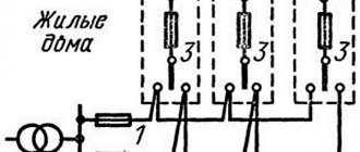
Modular contactor connection diagram
There are no universal solutions; each switch is connected to power and control lines in accordance with the manufacturer's recommendations. It’s not difficult to figure this out; a detailed description (as well as safety measures) is required in the passport and on the device body.
Moreover, the same contactor (meaning model) can be used for various projects and local solutions. To understand the development methodology, consider the connection diagram for a switch in push-button starter mode for an electric motor.
You can also turn on a powerful electric heater or water boiler. It does not matter whether the contactor is single-phase or three-phase. Fundamentally, only the number of contact groups influences the switching scheme.
Design Features
The main purpose of vacuum contactors is to turn on/off various devices and switch them with AC power circuits. A DC electromagnet is used to perform work processes. Each such contactor is equipped with a sealed arc extinguishing device, which serves as a vacuum chamber. In it, the switched circuit is turned off in a vacuum environment for 1-2 half-cycles.
This design became the basis for the creation of three-phase vacuum contactors with ratings of 160, 250, 400 and 630 A at rated voltages of 660 and 1140 volts. They are highly resistant to wear, and the number of operating cycles is 600 and 1200 per hour.
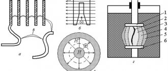
The device uses a block-type design with an insulating base (1), where all components are located. The diagram shows the elements - a vacuum chamber (2), an anchor axis of rotation (3) and the armature itself (4), a pole piece and core (5 and 6), a coil (7), an electromagnet base (8), and a tripping return spring (9), the axis on which the movable contact (10) rotates. Ultimately, the contactor consists of three arc chutes, an electromagnet and block contacts.
The vacuum chamber contains the main contacts, made in a cylindrical shape. There is a gap of 1.2 mm between them, gradually increasing to 2 mm. During operation, the gap can be adjusted once.
We should separately consider a vacuum chamber for arc extinguishing, which is distinguished by high arc-extinguishing and insulating properties, increased breakdown voltage between contacts, and rapid restoration of electrical strength in the intercontact gap.
The diagram below shows all the camera parts and how they interact with each other. The moving contact (1) is connected using a tripping spring to the electromagnet armature. The fixed contact (2) is installed in a housing (3), made in the form of two flanges. Metal-ceramic plates (4, 5) are fixed to the contact surfaces. To connect the moving contact (1) to the bottom of the chamber, a corrugated bellows (6) made of stainless steel is used. Thanks to this device, the moving contact moves without breaking the seal of the vacuum chamber.
Where and why it is used
Electromagnetic starters and contactors are built into a power network that transports current; it can be direct or alternating voltage; the work is used on electromagnetic induction. The devices are equipped with a set of signal contacts, through which the connected devices are powered. Some perform an auxiliary function, while others perform a working function.
Electrical installations and electric motors are controlled by starters, but do not protect them in the event of a voltage drop, since the power contact opens, and the operation of the device to which the electromagnet is distributed is suspended and independent activation is excluded.
What kind of lighting do you prefer?
Built-in Chandelier
To put the equipment into operation, you need to use the “start” button. This ensures safety, since accidents may occur due to spontaneous activation.
The starter connection circuits may include relays with thermal action; they are designed to protect electric motors and other installations from long-term operation. There are single-pole and double-pole magnetic starters. They are triggered when exposed to a current overload of motors through which voltage passes.
Arcing device
Electromagnetic blowing devices are widely used in DC contactors. When a magnetic field interacts with an arc, an electrodynamic force arises, which moves the arc at high speed. To cool the electric arc as quickly as possible, it is “driven” into a slot made of arc-extinguishing material, which has high thermal conductivity. When contacts 1 and 7 (figure above) split, an arc 14 appears between them. The arc can be considered as a conductor with current. MMF (magnetomotive force) is created by coil 3, under the influence of which a magnetic flux is created. This flow passes through the pole pieces 15, the coil core and the air gap, in which the electric arc burns. Below in the figure above, crosses highlight the direction of the magnetic flux between the poles of the system, directed beyond the plane of the drawing.
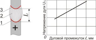
The current-voltage characteristic of the arc must be increased with increasing current to ensure conditions for extinguishing the electric arc. This can be achieved either by mechanically stretching the arc or by electrodynamic forces.
The figure below shows the dependence of the contact solution, at which the electric arc is extinguished, on the magnetic induction current, obtained by O. B. Bron on a contactor model.
The curves have the same character for all values of induction B - at a current of 5 - 7 A the curve will reach a maximum, after which the required solution drops with increasing current and at a current of 200 A all curves merge. This course of the curves can be explained by the following phenomenon. The electrodynamic force acting on a unit of arc will be equal to:
Where I is the current, and B is the magnetic field induction.
Let's consider the case shown in curve 1, when B = 0. The electrodynamic force is very insignificant at low current and has practically no effect on the process of extinguishing the electric arc. The conditions necessary for extinguishing are created due to the mechanical stretching of the arc by movable contacts. In this case, the extinguishing of the electric arc with increasing current occurs at a longer arc length.
If the current is more than 7 A, the electric arc begins to be affected by an electrodynamic force, which arises both due to the magnetic field of the supply conductors and due to the configuration of the arc itself (to a rough approximation, one can imagine that the electric arc always has the shape of part of a circle). These forces play a decisive role in the process of extinguishing an electric arc. The greater the current in the electrical circuit, the higher the electrodynamic force that stretches the arc. As a result, a contact solution of only 1.5 × 10⁻³ is sufficient to extinguish an electric arc at a current of 200 A. At this current, as soon as the contacts are mechanically separated, the resulting electrodynamic force will push the arc out of the intercontact gap at a speed of several tens of meters per second. In this case, the length of the electric arc at which it goes out can reach 0.1 m or even more.
The presence of an external magnetic field contributes to a sharp reduction in the contact opening of the contactor in the region of low currents and has an insignificant effect on the extinguishing process at currents of 100 A or more. The most optimal induction is B = 0.0069 T. Subsequent increases in induction have little effect on the arc extinguishing process, but require more power to create a magnetic field and increase copper costs for the coil.
Graphs of arc duration versus current are shown in the figure below:
In their shape they resemble the curves from the previous graph.
The contact solution required to extinguish the electric arc increases with increasing current in the region of low currents. With a fixed contact speed, it takes more time to achieve the required solution. In the region of high currents, the quenching process is determined by electrodynamic forces. The logic is simple - the greater the current, the greater the rate at which the arc is stretched by dynamic forces and, accordingly, the less time required for the electric arc to reach its critical length.
Although the use of magnetic blast at currents above 100 A may seem unnecessary (the graphs above illustrate this), this system is necessarily used in all contactors with currents of 100 A. The reason for using such a system is that the presence of an external magnetic field greatly “helps” the movement of arc reference points from electrical contacts to arc extinguishing electrodes - horns, which significantly reduces the degree of contact melting. Research has shown that an optimal magnetic field value exists for each current value. At high voltages, increased wear of the contacts occurs, since the liquid metal contact bridge that appears at the stage of opening the contacts is carried away and sprayed by the magnetic field.
Only in the region of low currents (up to 30 A) does the voltage of the disconnected circuit make the process of extinguishing the electric arc more difficult. In the range of currents above 100 A, where the electrodynamic force plays a decisive role, the value of the supply voltage has practically no effect on the contact solution. The contact solution, as a rule, is determined by the conditions for extinguishing low current and is taken within the range of (10 - 17) 10-3 m.
At low loads, the characteristics of the disconnected circuit also play an important role in the area where arc extinction occurs due to mechanical stretching of the electric arc. In the area of high currents, one should not forget about possible large overvoltages and repeated breakdowns due to a sharp drop in the current to zero under the influence of a strong magnetic field.
Methods for creating a magnetic field to extinguish an electric arc can be with parallel connection of a magnetic blast coil (voltage coil), with a permanent magnet, as well as with serial connection of a magnetic blast coil (current coil).
In the case of a current coil, it is flown around by the current passing in the disconnecting circuit. If the magnetic resistance is neglected, then we can assume that the induction is proportional to the switched current. Then formula (1) can be reduced to the form:
Thus, we can conclude that the force acting on a unit of electric arc is proportional to the square of the current.
It was previously shown that the required magnitude of the magnetic field for blowing must be in the region of low currents. A system with a current coil does not create the required magnetic field induction in this area (curve 4 in the figure above). The same figure shows the duration of the arc and the electrodynamic force that acts on it, from the current for a 150 A contactor. Arc time curves 1 - without magnetic blast, 2 - magnetic system with a current coil. In case 2, at a current of 10 A, the duration of the arc can reach 0.09 s. In this case, it becomes possible to sustainably burn an electric arc without extinguishing it.
The reliably switched-off current of a contactor with a current coil is approximately 20% - 25% of the rated current of the device (experimental data).
In the low current range, block contactors (low current contactors) with replaceable magnetic blast coils are used. The rated current of such coils is 1.5 - 40 A. When the switched current is low, a coil with a large number of turns is installed, thereby creating the necessary magnetic field to extinguish the arc in a minimum time.
We also must not forget that with a strong magnetic blast, a sudden interruption of the current is possible, which will lead to overvoltage in the inductive circuit. The block contactor can cut off a current of no more than three times the rated current of the magnetic blast coil.
The advantages of a system with a current coil include:
- This system works perfectly in the range of currents above 100 A. In this case, the magnetic field quickly blows the arc off the working surface of the contacts, thereby minimizing their wear.
- The direction of the current does not affect the operation of the system. When the direction of the current changes, the magnetic field also changes sign, but the force acting on the electric arc does not change its direction.
- Since the rated current of the contactor passes through the coil, it is made of large cross-section wire. This increases its mechanical strength and reduces the impact of shocks that occur during operation of the contactor. There are no high requirements for coil insulation, since the voltage drop across the coil is a fraction of a volt.
But since our world is not ideal, such a system also has its drawbacks:
- Poor arc extinction at low currents (5 - 7 A).
- High costs for coil material (large cross-section copper wire).
- The heat generated by the arcing coil heats the contacts.
But since such a system is reliable when extinguishing rated and high currents, despite its shortcomings, it has become quite widespread.
With a parallel system, the magnetic blast coil is connected to an independent power source. The magnetic induction created by the system is constant and absolutely independent of the current being switched off.
According to formula (1), the force acting on the arc is proportional to the switched current:
In the figure above, this dependence is displayed by curve 5 for the case when the MMF of the voltage coil is equal to the MMF of the current coil at rated current. With a current from 0 to In, the force that acts on the arc with a voltage coil will be higher than when using a current coil (parabola 4 goes below straight line 5). This property makes it possible to sharply reduce the burning time of the electric arc in the low current region. But in the case when I > In, the force acting on the arc with a current coil will be greater than with a voltage coil. However, for the arc extinguishing process this is not significant, since the main role is played by the forces arising in the arc contour itself.
Curve 3 (figure above) shows for a system with a voltage coil the dependence of the arc extinction time on the current.
For the same arc duration, the voltage coil performs better in the region of low currents, in contrast to the current coil, since a lower MMF is required. But do not forget about the disadvantages of such systems:
- The direction of the electrodynamic force that extinguishes the arc depends entirely on the direction of the current. Such a contactor cannot operate when the current polarity changes.
- The coil insulation must be designed for the voltage of the power source and is made of thin wire. Its location close to power contacts reduces the reliability of its operation (splashes of molten metal may fall on the coil).
- In the event of short circuits, a sharp decrease in the voltage at the coil power source is possible, which also sharply reduces the efficiency of extinguishing the electric arc.
Due to the above disadvantages, a system with a voltage coil is used (as a rule) to switch off small currents from 5 A to 10 A. In electrical devices with large switched currents, this system is not used.
A permanent magnet system differs little from a voltage coil system. The difference is that the magnetic field is created by a permanent magnet.
But we should also not forget that a permanent magnet has a number of advantages:
- There is no energy consumption to create a magnetic field;
- Copper consumption in the manufacture of contactors is reduced;
- There is no heating of contacts from the coil;
- It is highly reliable and works equally well at any current;
- The use of a permanent magnet makes it possible to reduce the arc burning time at low currents;
The force created by the magnetic field carries the electric arc into the arc chute . The purpose of the chamber is to localize the area occupied by hot gases and to prevent overlap between adjacent poles. Intensive cooling of the arc occurs when it comes into contact with the walls of the arc-extinguishing chamber, which leads to successful extinction (increase in the current-voltage characteristic). Arc-resistant ceramics should be used as the arc chute material.
Labyrinth-slit ceramics are the most advanced. The arc is driven into the tapering zigzag slit by a magnetic field (figure below b)). Due to good thermal contact with the chamber walls and an increase in the length of the arc, it is effectively extinguished. Compared to a conventional longitudinal slot (figure below a)), a zigzag slot significantly reduces the amount of hot gases emitted from the arc chamber, and, consequently, the exhaust area.