When power goes out for even a few minutes, businesses can suffer enormous losses. And for hospitals this situation is simply dangerous. Most facilities require uninterrupted power supply. To do this, it must be connected to several sources of electricity. Specialists with this approach use AVR.
What is an AVR and its purpose?
Automatic transfer switching or ATS is a system related to electrical switchboard input and switching distribution devices. The main purpose of the ATS is to quickly connect the load to backup equipment. Such a connection is necessary when problems arise with the supply of electricity from the main power source. The system monitors the load voltage and current and thus ensures automatic switchover to emergency operation.
ATS is necessary if there is a spare power source (an additional line or another transformer). If during an emergency the first source is turned off, all work will transfer to the spare one. Using an ATS will help you avoid troubles caused by power outages.
Requirements for ATS
The main requirements for ATS systems are as follows:
- It must have a high rate of power restoration.
- In the event that the main line stops working, the installation must provide electricity to the consumer from a backup source.
- The action is carried out once. Multiple switching on and off of the load, for example due to a short circuit, should not be allowed.
- The main power switch must be turned on using the automatic transfer system. Until backup power is supplied.
- The ATS system must monitor the correct functioning of the backup equipment control circuit.
Basic requirements for ATS:
- minimum time for the ATS to operate (no more than 1-2 seconds, ideally a fraction of a second) after turning off the main power source.
- 100% switching on of the ATS when the bus voltage disappears
- single launch of AVR. Repeated starting of the backup source is unacceptable without eliminating the short circuit.
Switchgears (RU, distribution board, ASU) are designed to receive, distribute and account for electricity in three-phase alternating current networks with a frequency of 50 Hz, as well as to protect lines during overloads and short circuits.
Operating principle of automatic reserve entry
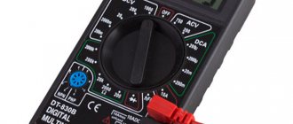
The basis of the ATS operation is monitoring the voltage in the circuit. Control can be carried out using any relays or microprocessor control units.
Reference! A voltage control relay (also called a volt controller) monitors the state of the electrical potential. In the event of an overvoltage in the network, the volt controller will instantly de-energize the network.
The contact group, which controls the availability of electricity, plays a major role in the automatic transfer system. In our case it is a relay. When the voltage disappears, the control mechanism receives a signal and switches to power to the generator. When the main network begins to operate normally, the same mechanism switches the power back.
Control cabinet specifications
Operating conditions for the AVR cabinet:
- in terms of resistance to climatic factors, the SHAVR cabinet according to OST32.146-2000 belongs to class K1;
- in terms of resistance to mechanical loads, the SHAVR cabinet according to OST32.146-2000 belongs to class MS1;
The average service life of an AVR cabinet is at least 20 years.
| Parameter name | Meaning |
| Type of current | alternating three-phase |
| Rated voltage, V | 400/230 |
| Frequency Hz | 50 |
| Type of climate control according to | GOST 15150-69 UHL 3 |
The electrical insulation resistance of the control circuits among themselves and in relation to the housing is not lower than:
- 100 MOhm – under normal climatic conditions;
- 5 MOhm – at high humidity;
The overall dimensions of the AVR cabinet (height, width, depth, weight) depend on the type and brand of components used and the power of the diesel generator set;
The composition of the ATS components can be changed to suit the specific needs of the Customer, which are specified during the Order process.
Typical scheme:
Basic options for the logic of ATS operation
ATS system with first input priority
The essence of the operation of this type of automatic transfer system is that the load is initially connected to power source No. 1. When an overload, short circuit, phase loss or other emergency occurs, the load switches to a backup source. When the electricity supply at the first is restored to normal parameters, the load is automatically switched back.
ATS system with second input priority
The logic of operation is the same as that of the previous type of system. The difference is that the load is connected to input 2. In the event of an accident, the voltage goes to input 1. After the voltage on the second source is restored, the voltage will automatically switch to it.
Distinctive Features
Modern ATS units provide automatic starting of the generator in the event of a power failure on the main line. In this case, such a unit controls the operation of the starter, the fuel valve, the preheating of the installation spark plug and the air damper drive. When the voltage on the main line is restored, the ATS independently turns off the load supply from the generator, due to which the entire installation gradually cools. In addition, automatic reserve entry has other functions:
- The unit must include a generator battery charger.
- Some models allow you to monitor the crankcase temperature of a gasoline engine to continuously control the choke depending on the engine heating level. Thanks to this function, overheating of the main working unit is prevented.
- More expensive models are equipped with powerful batteries that cope well with heavy loads.
- The AVR unit can be connected to a personal computer (RS 485 interface). The user can fine-tune the constants and parameters that will read all current measurements.
- Installing a GSM modem will allow you to remotely start and stop the generator via SMS messages. A specialist can control the operating mode of the unit at a convenient time, as well as read current telemetric data.
- Availability of built-in bypass. When the main control controller fails, the generator can be started independently.
- Availability of an “Emergency stop” button. The generator can be forcibly stopped if an unexpected situation occurs.
Main types of AVR cabinets and panels
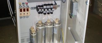
ATS panel for two inputs on contactors (starters)
Installing an ATS cabinet on starters is the easiest way to create backup power. This cabinet is the most budget-friendly option for installing an ATS. As a rule, automatic switches are used in ATS cabinets with 2 inputs. They are needed to protect the system from overloads and short circuits. Protection against phase imbalance and voltage surges is provided by a voltage relay. In addition, the relays become the “brains” of the entire automatic transfer system.
An ATS cabinet with two contactors works according to the following principle. Two contactors are connected to the first and second sources, respectively. The first contactor is closed, and the second has an open circuit. Electricity goes through input No. 1.
Attention! In the case when the ATS has priority logic for the second input, the situation will be the opposite: the circuit of the second contactor is closed, and the first one is open.
If the current supply at the first input disappears, but at the second it is normal, then the contacts of the second starter will close and the mechanism will switch to it. As soon as the voltage is restored at the first input, the circuit will return to its original state.
Using a relay, here you can adjust the delay time with which switching from one source to another will take place. The optimal delay is from 5 to 10 seconds; it will protect the system from false triggering of the automatic transfer switch. False triggering can occur, for example, in the event of a voltage dip.
Reference! To prevent both contactors from turning on at the same time, additional mechanical interlocks are used in ATS panels.
ATS panel for 2 inputs on motor-driven machines
They are best suited for use with current ratings of 250-6300A. When the current at the main input disappears, special electric motors receive a signal and charge the springs of the spare switch, switching the load to another input.
Where to buy an AVR cabinet?
E-shield LLC manufactures and installs AVR panels according to a standard or individual project. In the latter case, the selection of equipment and the specific design will meet the necessary requirements and comply with the conditions of use of electrical equipment. Our permanent staff includes experienced installers and engineers who ensure high quality assembly and commissioning.
E-shield LLC offers to order AVR switchboards with two or three inputs, designed for different rated currents and with any characteristics corresponding to the features of the objects.
Reliable and durable electrical cabinets from our company meet the requirements of state standards. Contact our specialists by phone to ask any questions you may have and place an order for the manufacture and installation of AVR cabinets with a quality guarantee. You can see the approximate price for equipment in the table above: when ordering, the cost will be calculated individually.
Features of the AVR of a private house
The most common method is with two inputs, where the first one has priority. When connected to the network, household loads mostly operate on one phase. If it disappears, it is not always convenient to connect the generator. It is enough to connect another line as a backup. With three-phase input, the power is controlled by a relay on each phase. When the voltage goes outside the normal range, the phase contactor is turned off, and the house is powered from the two remaining phases. If another line fails, the entire load is redistributed to one phase.
For a small cottage or dacha, a diesel generator set with a power of no more than 10 kW is used for a panel operating at 25 kW. Such a generator is quite enough to provide the house with the necessary minimum of electricity for a short time. If an emergency occurs, the voltage control relay switches the consumer bus to backup power and sends a signal to start the diesel generator set. When the main power is restored, the relay switches to it, after which the generator stops.
Self-production of the AVR unit
High-quality automatic transfer of a reserve for a generator is expensive, so many home craftsmen decide to make this device with their own hands, using the same parts as in standard factory units. The main and most expensive part is the multifunction controller.
To ensure the power part of the master, contactors are used, which are used to guarantee switching from the main line to the local network. In order to compactly place all the parts, you need to prepare a fairly spacious cabinet or panel, which will best suit the size of the unit being manufactured.
The traditional ATS circuit is always equipped with an automated control mechanism that operates using normal DC voltage. The high-quality implementation of this idea is entrusted to the power supply. Most often, specialists use a standard high-power battery, since under increased loads a low-power unit quickly discharges.
It is the power supply that controls the level of output voltage. It is worth noting that all components should be purchased exclusively from trusted retail stores, giving preference to well-known manufacturers. In order to avoid the most common mistakes during assembly, it is necessary to use a professional ATS circuit for the generator. With your own hands you can make a high-quality model that will meet all operational requirements.
When choosing a controller, you need to check the presence of an inverse air damper. This unit is especially useful in situations where the consumer is using a generator with a mechanical damper.
When all the elements are in stock, you can safely begin manufacturing the AVR. You need to start by installing all the elements and components in the internal compartment of the electrical panel. This process must occur in such a way that no intersections are formed between the conductors, and all contacts and terminals are easily accessible. Next, the power section and controllers are connected.
Parallel connection of a backup generator with a centralized power grid is considered unacceptable. Otherwise, the uninterruptible power supply may be severely damaged, even to the point of complete breakdown of all components. To protect equipment from such negative consequences, you need to purchase special boards that provide both manual and automatic switching to reserve input. On sale you can find universal varieties of high-current load switches, as well as multifunctional automatic voltage regulators for the generator used.
During the connection process, the presence of two powerful cables that are included in the automatic backup panel must be taken into account. One of them must be designed for the main network, and the second - for the backup power line. Their alternate use is due to different operating algorithms of the equipment. But at the output, only one power cable is pulled to the consumer.
Classification of ATS and implementation options
Backup power is provided and its automatic input can be from a separate generator, battery or a separate line.
In turn, all ATS systems according to their action are divided into:
- One-sided. One section or input is working (main), and the second is backup. If the operating voltage disappears, the reserve is switched on.
- Double sided. When there are two separately powered sections and, accordingly, two lines are working, and when one of them is turned off, the other is a backup.
Also, the ATS can be with or without power restoration according to the normal circuit. In the second case, the non-working network is completely extinguished, and even if the power is restored again, the circuit will not work as before on two lines.
Features of working with household generators
In order to organize the automatic introduction of a reserve in the house, you can use an autonomous generator as a source of backup power. It will make it possible to provide an entire house with electrical energy for a long time, and the size of the connected load depends on the power of the generator itself. Here is the connection diagram:
The introduction of a generator as a source of electricity instead of mains voltage can be practiced in single-phase and three-phase networks, taking into account the generator model. However, in order for this process to be fully automated, it is necessary that the generator be equipped with a starter, and you will also need a special unit consisting of a set of switching devices that turn on the starter only during startup and turn it off when the mains voltage is restored. It looks like this:
This generator block is compatible with any type of engine and has three positions: “Stop”, “On”, “Start”. True, in winter it is necessary to warm up the internal combustion engine, but this unit can be programmed taking this feature into account. It is mounted on a DIN rail in the distribution panel.
The video clearly explains the diagram by which you can make automatic input of a reserve for a generator with your own hands:
Battery-powered ATS
With the development of converters that transform direct current into alternating current, it becomes possible to use, for example, a car battery as a backup power source. In addition to the battery, you will need to purchase a modern car inverter that converts 12 Volts of DC voltage into 220 Volts of AC.
True, this source can hardly be used for power loads, but it can easily provide lighting circuits with a stable voltage for the duration of a short accident on the line. In this case, the duration of operation will depend on the power of consumers and the capacity of batteries.
To increase the capacity, you can connect several batteries in parallel. The connection diagram of the ATS system itself can be implemented using a starter.
The starter is included in the main circuit, and if there are problems in the network, its moving part disappears, thereby its disconnecting block contact, introduced into the battery circuit, starts the automatic power supply system. This method is less expensive than a generator, but is not capable of delivering current for a long time for powerful household appliances.
Application of Logic Controller
For two three-phase power supply networks, ready-made ATS units are used using a logical digital controller, which can take into account many parameters required to create an ideal system. It has all the necessary markings and instructions for control and connection.
However, before you connect the module and purchase it, you need to think about whether there is a backup power source with a more reliable power supply. Since there is no point in connecting it to the same three-phase network system, that is, powered by a single 6/0.4 kV transformer.
Three-phase AVR cabinets (AVR3 series)
AVR3 cabinet line
AVR3 cabinets are designed to switch three-phase loads from the main input to the backup one. Typical modifications of three-phase ABP3 cabinets are developed depending on power and current.
| Cabinet modification | Maximum power, kW | Maximum current, A | Overall dimensions (HxWxD), mm |
| AVR3-100-0 | up to 50 | up to 100 | 700 x 500 x 250 |
| AVR3-80-0 | up to 40 | up to 80 | 700 x 500 x 250 |
| AVR3-63-0 | up to 30 | up to 63 | 500 x 400 x 200 |
| AVR3-50-0 | up to 25 | up to 50 | 500 x 400 x 200 |
| AVR3-40-0 | up to 20 | up to 40 | 500 x 400 x 200 |
| AVR3-32-0 | up to 16 | up to 32 | 400 x 300 x 200 |
| AVR3-25-0 | up to 12 | up to 25 | 400 x 300 x 200 |
Main technical characteristics
| Rated operating voltage Ue | 380 V |
| Rated operating voltage Ue of control circuits | 220 V |
| Level of protection against dust and moisture | IP54 |
| Working temperature | from –5°С to +40°С |
Additional options
| Type | Description |
| PKL-11 | Contact attachment PKL-11-UHL4 |
Possibility of outputting “dry contact” signals about the ATS operating mode.
Controlled parameters
- Three-phase voltage monitoring in four-wire networks with neutral
- Overvoltage control for any phase from 240V to 298V (switch, 10 positions)
- Control of voltage reduction of any phase from 162V to 220V (switch, 10 positions)
- Phase sequence control
- Phase failure monitoring
- Control of “sticking” of phases.
Single-phase AVR cabinet (AVR1 series)
Purpose
The AVR1 cabinet is designed to switch single-phase loads from the main input to the backup one.
Operating principle
The principle of operation is based on the presence of voltage on the intermediate relay, due to which switching is carried out.
Modifications
The single-phase cabinet ABP1 has only one modification depending on power and current.
| Cabinet modification | Maximum power, kW | Maximum current, A | Overall dimensions (HxWxD), mm |
| AVR1-25-0 | up to 4.5 | up to 25 | 400 x 300 x 200 |
Main technical characteristics
| Rated operating voltage Ue | 220 V |
| Rated operating voltage Ue of control circuits | 220 V |
| Level of protection against dust and moisture | IP54 |
| Working temperature | from –5°С to +40°С |