Many users underestimate the importance of the power supply in ensuring correct and stable operation of the computer, although this should not be done. It is a good power supply that will determine how confidently, quickly and efficiently all components of the computer will work. If you decide to replace the power supply with a new one, you need to connect it correctly. This issue will be considered in more detail.
Replacing a power supply is not as complicated a process as it might seem at first glance. If you approach the matter thoroughly and with due care, then the procedure for removing the old power supply and installing a new one will take place in a matter of minutes.
Selecting a power supply
The power supply (PSU) is selected taking into account the following features of the personal computer (PC):
- case form factor: there are several of them, ATX is the most common;
- power of installed modules: the largest consumers are the processor and video card, sometimes there can be 2 video cards;
- form factor of the power supply itself;
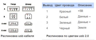
- type of pinout of module connectors: the power supply must have them;
- the number of cables and contact connectors should ensure the connection of all PC modules.
There are several dozen manufacturers of power units for PCs. Among the popular ones are: Corsair, FSP, SeaSonic, Thermaltake, ZALMAN, DeepCool, ENERMAX, ASUS, Gigabyte.
Serial connection of elements.
When connecting batteries in series, two circuits are distinguished: series-complementary and series-interfering. In a series-complementary circuit, the positive terminal of the first battery is connected to the negative terminal of the second battery; the positive terminal of the second battery is connected to the negative terminal of the third battery, etc. (Figure 3.11.)
Figure 3.11. Serial connection of batteries.
With this connection of power supplies, the same current will flow through all elements:
Itotal=I1=I2=I3
The indices in the current designations indicate the numbers of individual power sources (elements or batteries). And the total voltage in a series connection is equal to the sum of the voltages (EMF) of the individual elements:
Total = E1 + E2 + E3.
When power supplies are switched on in series, they are connected to each other by pins of the same name. But in practice, such a scheme is not used or is used but very rarely.
Step-by-step instruction
The computer should be disconnected from the power supply. Disconnect all wires of peripheral devices: keyboard, monitor, mouse, speakers, Internet, video camera, etc.
Remove the side covers from the PC and place the case on its side.
Disconnect all wires with connectors from the indoor modules. Some connectors have locking latches. They should be bent before disconnecting. Remove the screws from the power supply unit that hold it in the case. Usually there are 4 of them. Remove the power supply from the case.
Installation in the case
- Insert the new power supply into the system unit case, and the holes for fastening the screws on the power supply should match the holes on the PC case. Screw in the mounting screws.
- Check the rotation of the fan by pushing it by the blade. It should rotate freely, without jamming.
- Remove the fixing tape or tie and disassemble the wires so that they do not interfere with each other.
Connecting to the motherboard and other components
To connect the power supply to the motherboard, you need to connect the power supply wires to the modules one by one, taking into account the pinout. The motherboard may have 20 or 24 contacts, which are also called pin, translated from English as “pin contact”.
The processor power connector is made of a separate cable with a 4 or 8 pin connector. Additionally, there may be a cable for connecting a cooler, also with 4 contacts.
CPU power connector on motherboard 8 pin
Simple video cards, or “plugs” as they are also called, receive power through the PCI slot. But relatively powerful models have additional power through connectors with 6 or 8 (6+2) contacts.
The remaining modules have 4 contacts for connecting various devices:
- hard disks;
- DVD/CDROM drive;
- additional power supply for the video card;
- additional coolers for PC cooling.
Connection diagram of the power unit to computer modules
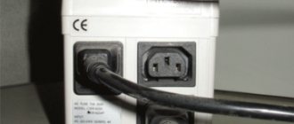
Make sure that the wires do not interfere with the rotation of the fans installed inside the system unit case. After completing the connections, you need to check the position of the power supply key and switch it to the “Off” state, it is marked “0”. Do not connect the power cord to the network when the power supply button is turned on.
First insert the power cord into the power supply and then connect it to the network. Move the key on the power supply to the “On” position, marked “I”. Perform a test start of the PC in the standard way through the start button on the case.
If all modules are connected correctly, the computer will start and the operating system will load.
Otherwise, a beep will sound indicating an incorrect connection. You should turn off your PC by pressing the start button on the computer case and holding it down for 10 seconds. If the shutdown does not occur and the signal continues to sound, turn off the power supply with the key.
Check that all connections are correct. Pay attention to the quality of the contact connections. When connecting the connectors, press the block until the latch clicks. In doubtful cases, reconnect the wire and restart the computer.
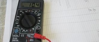
How to test an ATX power supply without a computer
Expert opinion
Alexey Bartosh
Specialist in repair and maintenance of electrical equipment and industrial electronics.
Ask a Question
To start a power module that is not connected to the computer, you need to close 2 contacts on the cable for the motherboard with a 20 or 24 pin connector. The green wire (PS-ON) is responsible for turning on the PC; it must be connected to the black wire – “ground”. However, you cannot turn on the power supply without load. Pulse units without load can produce very high voltage, which will damage the electrical elements of the power supply itself.
Any device for the system unit can be used as a load. For example, a DVD drive or hard drive. By connecting the load and closing the PS-ON contact, you can connect the power supply to the network and press the “Power on” button on the power supply. The rotation of the fan and a characteristic hum will indicate the operation of the power module.
Common Board Level Errors
In general, multilayer boards have solid ground and power planes to ensure signal integrity to the greatest extent possible.
The first step is to select the ground connection points on the chassis and on all printed circuit boards. Some inexperienced developers view the earth as a kind of magical place in which all clues disappear and all miscalculations are leveled out. Sometimes they select a ground point first, but do not provide separate paths for return currents to that point from different types of circuits. A similar error is illustrated in Figure 2.
Rice. 2. Errors leading to noisy ground
Let's start with the starred ground point on the +5V power supply. The noise generated by the digital circuits will end up in both the 5V power supply and ground. It is clear that the analog circuit requires a “pure” +3.3 V voltage, but we were too lazy to route separate ground and +5 V rails to the points marked with asterisks on the power supply. A linear LDO regulator is needed to create clean 3.3V, or so we think. In reality, the output voltage of a linear regulator will always be exactly 3.3 V above the reference voltage or ground potential. Therefore, if the LDO is doing its job and the ground potential is jumping up and down like a quivering red meter needle, the +3.3V output voltage will follow the ground potential. Now let’s ask how long it will take to find the reasons for the incorrect operation of a module that does not provide separate connections of digital and analog circuits to the power source? The best way to connect an analog circuit is shown in Figure 3.
Rice. 3. Proper ground and power connections. It is assumed that the connection points have clean ground and power.
The statement that at the points marked with 3 asterisks in the figure, ground and power are clean, means that at these points they are homogeneous, there is no differential noise between ground and power. Ideally, the output impedance of the power supply should be almost zero, or the output should have decoupling capacitors with low equivalent series resistance in the frequency range of interest. The individual conductors that connect various circuits to ground and power points also have their own resistance and inductance. We rely on this resistance and inductance to isolate noisy circuits from clean circuits. Series-connected resistance and inductance, as well as decoupling capacitors at the outputs of the circuit blocks, form a low-pass filter. If the conductor leading to the circuit block is relatively short, a discrete resistor or inductor may be required.
Rice. 4. Capacitor with its inherent parasitic components
Ensuring decoupling is not so easy, since capacitors have parasitic inductances. In practice, the capacitor is described as a series RCL circuit (Figure 4). Capacitance dominates at low frequencies, but above the series resonance frequency (SRF), shown for various capacitor values in the graphs (Figure 5), there is a region in which the capacitor impedance is inductive. Thus, a capacitor is only useful for decoupling in the frequency range near or below its SRF, that is, where its impedance is low.
Rice. 5. Six capacitors of different values and their own resonant frequencies
Figure 5 shows typical frequency characteristics of capacitors of different ratings [1]. The figure clearly shows the natural resonant frequencies (declines in the graphs). These characteristics also show that at low frequencies, capacitors with higher capacitance values (having lower impedance) provide better isolation than capacitors with lower values. To plot the frequency characteristics of capacitors, you can use free SPICE programs [2...4].
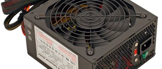
Overview of power supply circuits
The main part of the power supply block diagram, ATX format, is a half-bridge converter. The operation of converters of this type is to use push-pull mode.
Stabilization of the output parameters of the IP is carried out using pulse-width modulation (PWM controller) of control signals.
Switching power supplies often use the TL494 PWM controller chip, which has a number of positive properties:
- acceptable performance characteristics of the microcircuit. This is a low starting current, speed;
- presence of universal internal protection elements;
- Ease of use.
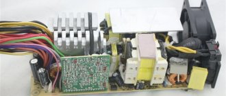
Simple switching power supply
The operating principle of a conventional pulse
The power supply can be seen in the photo.
The first block performs the change from alternating current to direct current. The converter is made in the form of a diode bridge, which converts voltage, and a capacitor, which smoothes out oscillations.
In addition to these elements, additional components may be present: a voltage filter and thermistors. But, due to the high cost, these components may not be available.
The generator creates pulses with a certain frequency that power the transformer winding. The transformer performs the main work in the power supply; this is galvanic isolation and conversion of current to the required values.
Next, the alternating voltage generated by the transformer goes to the next block. This block consists of voltage equalization diodes and a ripple filter. The filter consists of a group of capacitors and a choke.