The development of technology has led to the use of modern lighting systems in domestic premises, apartments and private houses. The use of LED chandeliers with remote control is increasingly becoming fashionable and practical. Stadiums, concert halls and other rooms and areas with large sizes and ceilings, where the light needs to be controlled remotely, are in great need of equipping this kind of lighting. Installing an LED chandelier allows you to turn on or off the light while in bed, after which you will not need to walk in the dark. But, like all equipment, sometimes such equipment requires repair.
Installation and fixation of LED chandelier
LED chandeliers with remote control, like other types of lamps, are attached to the ceiling using standard installation devices supplied in the kit. In most cases, this is a strip that must be secured to the ceiling using dowels. They often also come included. If they are not there, which is typical for the cheapest Chinese chandeliers, then you need to purchase fasteners separately.
Attaching the chandelier to the bar.
Holes for installing any LED chandelier are drilled in the ceiling using a drill equipped with concrete drills. First, the strip is secured to the dowels, then the lamp is attached to it. The order of work depends on the design of the chandelier and is almost always described in the instructions.
A strip fixed to the ceiling.
If the chandelier is large and heavy, it is better to hang it on a hook. Older houses already have such hooks.
Hook for hanging lamps.
For hanging serious chandeliers in more modern homes, you can purchase an anchor with a hook. It expands in the drilled hole and can withstand heavy loads.
Anchor with hook for hanging heavy lamps.
Read more about installation methods: Mounting and installing a chandelier
Choosing a chandelier
Combined chandelier with LED lighting Lighting
is a useful tool for designers and decorators. LED chandeliers do an excellent job of creating atmosphere and situational zoning of a room. The design of the lamps uses brass, bronze, stainless steel, chrome, nickel and silver plating, crystal, crystals, porcelain. The choice of chandelier is based on the permissible dimensions, area and required lighting intensity: living room and kitchen - 200 Lux, children's room and bedroom - 150 Lux, hallways and bathrooms - 100 Lux. For your own safety, you should pay attention to the documentation. The seller must provide a quality certificate, a sanitary permit describing the materials used, and a warranty card.
Ceiling lamps are distinguished by the type of mounting:
- built-in (in a drywall box, under suspended ceilings) - a hole is mounted according to the parameters;
- overhead - small lamps of simple shapes or volumetric chandeliers of the most intricate designs;
- suspended - more suitable for halls and halls with ceilings higher than 2.7 m, less popular in residential buildings.
The type of electrical appliance can be matched to any space style. There are horn-shaped (supplemented with lampshades and shades) and hornless models.
Hanging
Built-in
Invoice
The light can be supplied only by LED lamps or halogen lamps with LED backlighting.
Wiring diagram
To connect any chandelier, it is not necessary to know its internal structure. A chandelier with a remote control is connected to the network like a regular lamp:
- phase wire to terminal L;
- zero to terminal N;
- if there is a protective conductor, it is connected to the terminal marked with PE or the earth symbol.
Connection diagram for a luminaire via a single-key switch using a distribution box.
The diagram for connecting the lamp as a “black box” using a junction box is shown in the figure. The wall light switch is the main one. If it is turned off, the remote control will not affect the operation of the lighting in any way.
Important! If a lamp of protection class 1 is used, then protective grounding is the only (in addition to the main insulation) measure of protection against electric shock in the event of breakdown of the insulating layer. It cannot be used in TN-C networks - it will work, but will not provide security.
But knowledge of the internal structure will not be superfluous for understanding the operation of the device as a whole, as well as for performing repair work, if necessary.
Block diagram of a chandelier with remote control.
Most chandeliers controlled by remote control contain a remote control module that switches loads, which are lighting fixtures. Usually there are 1..3 of them; ordinary incandescent lamps (or groups thereof), LED or halogen lamps can be used.
Remote control modules can be assembled using different element bases and using different circuits, but most of them have the same block diagram:
- The receiver is used to receive, amplify and filter the signal transmitted by the remote control. Infrared communication channels between the transmitter and receiver, common in household equipment, are rarely used in chandeliers due to the high level of thermal interference emitted by the lamp. In simple lamps, control is carried out via a radio channel, in advanced ones – via Bluetooth or WI-Fi. The last two options are often used in complex devices with adjustable brightness or with lighting effects that are controlled through a mobile gadget application.
- The decoder receives the generated sequence of pulses from the receiver and “decrypts” the command. Depending on the task, it generates a signal to turn on or off one of the loads, and in complex models to change the brightness level of the glow.
- The formed team is strengthened in the power block. If brightness adjustment is not needed, the load is switched by an electromagnetic relay. If you need to change the brightness or color, the power unit is a PWM controller with electronic keys.
- The power supply generates a constant voltage to supply all elements of the circuit.
If the load is halogen or LED lamps, then the chandelier will contain additional control devices.
Block for halogen lamps
Halogen lamps are connected to a 220 volt network not directly, but through a step-down transformer . Nowadays, for the most part, not ordinary transformers with a magnetic core and two windings are used, but electronic transformers. They work on different principles, so their dimensions and weight are lower. At the same time, reliability is also lower, but the level of interference generated into the supply network is higher. Such a transformer is switched from the 220 volt side - there are lower currents at equal power, and the durability of the relay contacts is higher.
Control circuit for halogen lamps.
The presence of halogen lamps and a transformer of any type does not affect the connection of the chandelier to a 220 volt network. It must be borne in mind that when replacing lamps, their total power should not exceed the load capacity of the transformer.
| Lamp type | Voltage, V | Power consumption, W |
| Visico ML-075 | 12 | 75 |
| NH-JC-20-12-G4-CL | 20 | |
| Navigator 94 203 MR16 | 20 | |
| G4 JC-220/35/G4 CL 02585 Uniel | 35 | |
| Elektrostandard G4 | 20 |
When installing, you need to sum up the total power of the lamps and compare it with the highest permissible (indicated on the transformer body).
LED block
The LEDs are turned on through a current stabilizer - driver. It reduces the voltage on serial and parallel strings of LEDs and stabilizes the current through them.
LED control circuit.
In advanced models, which allow you to control not only turning the LEDs on and off, but also adjusting their brightness and changing the color of the glow, the driver is combined with a power unit. The output transistors of the PWM regulator serve as the keys.
Selection of control panel (PU)
The presence of a remote control is a life saver when you need to trench the walls or spoil their appearance with cable ducts to get the switch out. Although a regular switch is often left to supply power. Only after turning it on will you be able to use the remote control. The PU can come complete with a chandelier, but universal wireless control panels are produced that connect to any lamp or control several devices at once. The lighting in the apartment is combined with the smart home system.
The controller with the antenna is placed in the housing of the lighting device, in the ceiling cavity near the suspension or in the mounting box. Power is supplied from a 220 V network. The stationary remote control is mounted on the wall and is equipped with an audio search for the remote controller.
Wireless equipment can operate on different types of signals:
- infrared - the most budget option, works at short distances up to 8 m, only with direct visibility;
- radio - the most common, can work through partitions at distances of up to 30–100 m;
- Wi-Fi - has the widest capabilities, including control from a mobile device, the range is extended to 300 m.
The number of control channels depends on the number of luminaires and ranges from 1 to 4. Typical diagram: buttons A, B control modes, C - full on, D - full off. The total lamp switching power is 1 kW. LED sources are controlled via a 0.2 kW channel.
To avoid interference in radio remote controls, the sensor and receiver are tuned to the same frequency. For the operation of the mobile part of the equipment, it is enough to be powered by rechargeable batteries or replaceable batteries of AA, AAA format.
How to bind a remote control to a chandelier
In some remote control systems, it is necessary to bind the remote control to the lamp (synchronize). This procedure can be done with one remote control and several lamps in different rooms and control them using a single device (although you will have to carry the remote control with you all the time). You can try to attach your own remote control to each lamp in the room and control them independently. The procedure varies slightly among different manufacturers, but in general it is approximately the same:
- supply voltage to the chandelier from the wall switch;
- wait a few seconds, point the remote control at the lamp;
- press the button specially allocated for synchronization;
- After a few seconds, the lamp will respond in the form of one or more blinks and switch to glow mode.
Remote control with a binding button (Setup).
The button for primary synchronization is most often marked with a radio signal symbol, but not necessarily. This could be a button for one of the channels or just a button to turn on the light. Usually the entire setup procedure, indicating the buttons, is described in the instructions.
Installation work
Before starting installation, you need to deal with the wires coming out of the ceiling. Usually three wires come out, two of which are phase and one is neutral. Thus, the chandelier can be controlled using a two-key switch. After deciding how to make a chandelier with a remote control with your own hands, you need to secure it.
To secure the entire structure, a special fastening strip is used instead of a traditional hook. If there are suspended ceilings, fastening is carried out using an embedded bar fixed to the main ceiling. Vago terminals are used to connect the wires. The conductors are connected to each other by corresponding colors. If the colors do not match, the identity of the wires is determined using an indicator screwdriver or a multimeter.
Advantages and disadvantages
The ability to control the light from a remote control or other control device has the following advantages:
- Availability of installation and connection.
- Smooth adjustment of lighting characteristics of lamps.
- Programming a schedule for turning the lights on and off, creating a “presence effect”.
- Optimization of energy consumption.
- Saving the working life of lamps.
The disadvantages of systems for controlling lighting devices at a distance are manifested in the high cost of equipment and the influence of extraneous factors on the nature of their operation, for example, such as precipitation for outdoor devices, as well as the movement of warm air indoors.
Double and single switch
To connect a chandelier with a single switch, all wires from the light bulbs are combined into two connections - phase and neutral. In most cases, you can connect wires based on the color of their insulation. After the phase and neutral connections are formed, they are connected to the wires from the switch. This can be seen in Scheme 1.
The 4-, 5-, 6-arm version of the chandelier, as a rule, is connected with a double switch. It allows you to divide the chandelier lamps into two groups and turn them on separately. Scheme 2. The connection diagram for a two-key switch consists of dividing the electrical wires from the chandelier arms into 3 connections (L1, L2, N). The first and second are the phase wires, the third is for the neutral.
- Connect all the blue “zero” conductors on the chandelier to each other; to do this, you can twist them or connect them in terminals.
- Divide the remaining phase wires into two groups.
- Combine the first group (activated with the left key).
- Combine the second group (activated with the right key).
The phase and neutral bare wires must not be allowed to come into contact with each other, otherwise a short circuit will occur. Check for correct operation. Press the keys on the switch one by one. If everything works correctly, then the chandelier is mounted under the ceiling. You can use it. How to connect a chandelier to a double video switch, see below:
Principles of controlling a chandelier from a distance
The traditional way of turning on the light from a conveniently located switch on the wall has one definite advantage: it cannot get lost and is always in a familiar place - at the entrance to the room.
Small remote controls can be accidentally moved to the side, and after a while you have to look for them. For this reason alone, it is recommended to combine two methods in lighting control:
- stationary switch;
- mobile remote control.
The rules for reliable connection of a chandelier with a stationary switch are described in the article about the safe connection of a chandelier and a switch with wires. Electrical diagrams of their installation are also provided here, taking into account the internal design of lamps with different numbers of light bulbs.
Therefore, we immediately analyze the principle of operation of a chandelier from a remote control, which is based on the method of transmitting commands - electrical signals via radio waves using:
- a radio transmitter located inside a small-sized remote control;
- a radio receiver that receives commands sent only from a specific source, which are processed here automatically and converted into electrical signals that light up light bulbs.
The principle of remote control of a chandelier is explained in the picture.
A radio command is created by pressing a button on the remote control and transmitted over the air, received by the antenna of the radio receiver built into the electronic device - the controller.
- power supply:
- receiving radio signals;
- logic;
- switching power circuits.
All of them are made in a very small volume, for which there is enough space inside the lamp or next to it.
Selecting a distance
The receiver and transmitter can be created to work together at different distances. For a room, a distance of 8 meters is sufficient, created by most budget models, consisting of:
- controller;
- remote control;
- current source.
The influence of interference and extraneous signals
Now remote controls and controllers are installed by many owners. In a multi-story building, a situation may arise where a radio command from a nearby neighbor will be received by your controller. To avoid this, choose kits that work only in pairs with each other.
Configuration of such equipment is carried out at the factory and is not available to users. There is only one drawback to this positive point: if a breakdown occurs in the remote control or controller, then you will no longer be able to use them individually - you will have to purchase a new complete set.
Number of radio control channels
The usual number of buttons on the remote control determines the switching capabilities of the lamps. Modes A, B, C, D are created by simply pressing the corresponding button.
Switched load power
Light sources consume different amounts of electricity. In order for the controller to work reliably with most chandeliers, its output contacts are made powerful, capable of switching a 1 kW load. For household lighting devices, this is quite a large margin, even when using incandescent lamps.
It is made specifically and takes into account the fact that fluorescent and energy-saving lamps create four times the rated current when starting up.
Power supply for remote control and controller
The receiver and transmitter electronics require electrical power to operate. Regular batteries are installed inside the portable remote control, and the chandelier's automation is powered from a stationary network through a power supply. Therefore, it is necessary to correctly supply the mains voltage to the controller: phase and operating zero. They must be connected to the terminals corresponding to the symbols.
In this case, one interesting feature of the circuit may arise, combining operation from a wall switch and a portable remote control at the same time. It is explained by the fact that the controller does not recognize the method of supplying voltage: if the light is turned off by a remote transmitter and turned on by a switch, then the chandelier should light up.
This method can be simulated by randomly disconnecting the voltage of an apartment or house from protection systems when faults occur in the electrical network and then automatically restoring power. When the chandelier switch is not turned off, the existing logic of the devices will normally turn on the light and leave it burning against the will of the owner.
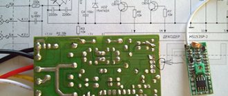
Repair process
The problem with the faulty controller was that more than one relay would not turn on. And sometimes one relay might not turn on. That is, if one more relay can be turned on, then the second and especially the third are no longer turned on.
To repair, you first need to make sure that the remote control is working (the batteries are normal, and when you press any button on the remote control, the indicator lights up), and supply power to the controller:
We connect the controller to carry out measurements and checks during the repair process
I connected it, it's very convenient. I inserted both wires N (black) into the terminal block, although either one is enough. The fact is that I do not connect the load, and wire N, if it dangles, can short-circuit to the output phase wires. The presence of output voltages can be checked by connecting 3 load lamps. But you can do it simpler - check the presence/absence of phase at the outputs with a phase indicator.
First of all, we check the supply voltage. We measure with a conventional multimeter, switched to constant voltage mode, on the electrolytic capacitor of filter C3. In relation to the common wire (minus the diode bridge and capacitors C3, C4, as is more convenient).
The voltage when the relays are turned off (almost no load, idle) on the filter capacitor is 11.2V; when any of the relays is turned on, it drops to 6V. At this voltage, even if the decoder gives a signal to open the transistor and it opens, the relay will still not turn on.
Naturally, suspicion immediately fell on the part of the electrical circuit responsible for power supply. Namely, to the limiting capacitor C2 in front of the diode bridge.
It says 155J. This means 15x10^5 picoFarads. And since there are a million picoFarads in 1 microFarad, this means that the capacitance of the capacitor is 1.5 μF. The voltage is clear, 250V.
If its capacitance has dropped, then it greatly limits the current of the diode bridge, and under load the voltage at the bridge output (and at the input, in the first place) drops significantly.
Another possible culprit for the drawdown is the electrolytic capacitor at the output of the diode bridge 470 uF 25V.
We change the 1.5 µF capacitor.
Now we measure the voltage at the output of the diode bridge in four operating modes:
- idle: 12.9V,
- switching on one relay: 12.2V,
- switching on two relays: 11.7V,
- switching on three relays: 10.5V.
Everything works fine!
Other malfunctions of chandelier controllers are below: