Checking the input resistance
So, they gave us a 350-watt Power Man power supply for repair.
What do we do first? External and internal inspection. Let's look at the "offal". Are there any burnt radio elements? Maybe the board is charred somewhere, or a capacitor has exploded, or it smells like burnt silicon? We take all this into account during the inspection. Be sure to look at the fuse. If it burns out, then replace it with a temporary jumper for about the same amount of Amperes, and then measure the input resistance through two network wires. This can be done on the power supply plug with the “ON” button turned on. It should NOT be too small, otherwise, when you turn on the power supply, a short circuit will occur again.
Current limits
If you think that any arbitrariness is possible in the power supply circuits of a personal computer, you can say goodbye to this thought. The international standard IEC 60950-1, the logo of which is in the title of the article, declares a power limit of no more than 240VA for each bus. The physical meaning of such a limitation is to prevent a situation in which the emergency power consumed in the event of a short circuit can be perceived by the current protection circuit as permissible (consumed by the load), which can lead to the destruction of device elements and even fire.
In the case of direct current, we can talk about 240 Watts, which sets a limit of 20 A for a 12-volt line. Bypassing this limitation is very simple: just distribute the voltages across different buses, as, for example, Chieftec does in the APS-500C power supplies:
As follows from the information on the power supply itself, a current of 18A is supplied through each of the +12V1 and +12V2 lines. Typically, one of them is delegated to power the processor, the other is used for drives and related peripherals. Each of them is served by its own current protection circuit: the sheep are safe, the requirements of IEC 60950-1 are met, and the food is normal.
The 700-watt unit from FSP Group also uses an extensive method: 12-volt lines are divided into four channels, each of which is limited to 18-amp current consumption. At the same time, the total power of the four-channel regulator is limited to 680 Watts, which formally means that the total current of four 12-volt channels should not exceed the limit of 56.6 Amperes. (680W/12V=56.6A). The attentive reader will note that, according to an additional comment on the label, there are more stringent restrictions: the total current on the +12V lines must not exceed 50A, and the total output current is limited to a limit of 70 Amps. Obviously, multiplying 18A by four channels does not provide any useful information.
We measure voltages
If everything is OK, we turn on our power supply to the network using the network cable that comes with the power supply, and do not forget about the power button if you had it off.
Next, measure the voltage on the purple wire
My patient showed 0 volts on the purple wire. I take a multimeter and connect the purple wire to ground. Ground is black wires with the inscription COM. COM is short for “common,” which means “general.” There are also some types of "lands":
As soon as I touched the ground and the purple wire, my multimeter made a meticulous “ppiiiiiiiiiiiiiiiiiiiiiiiiiiiiiiight” sound and showed zeros on the display. Short circuit, definitely.
Well, let's look for a circuit for this power supply. After googling the Internet, I found a diagram. But I found it only on Power Man 300 Watt. They will still be similar. The only differences in the circuit were the serial numbers of the radio components on the board. If you know how to analyze a printed circuit board for compliance with the circuit, then this will not be a big problem.
And here is the circuit for Power Man 300W. Click on it to enlarge to full size.
We are looking for the culprit
As we see in the diagram, standby power, hereinafter referred to as standby power, is designated as +5VSB:
Directly from it goes a zener diode with a nominal value of 6.3 Volts to the ground. And as you remember, a zener diode is the same diode, but connected in reverse in circuits. The zener diode uses the reverse branch of the current-voltage characteristic. If the zener diode were live, then our +5VSB wire would not short to ground. Most likely the zener diode has burned out and the PN junction is destroyed.
What happens when various radio components burn from a physical point of view? Firstly, their resistance changes. For resistors, it becomes infinite, or in other words, goes into a break. With capacitors it sometimes becomes very small, or in other words, goes into a short circuit. With semiconductors, both of these options are possible, both a short circuit and an open circuit.
In our case, we can check this in only one way, by unsoldering one or both legs of the zener diode, as the most likely culprit of the short circuit. Next, we will check whether the short circuit between the duty switch and ground has disappeared or not. Why is this happening?
Let's remember some simple tips:
1) When connected in series, the rule of greater than greater works, in other words, the total resistance of the circuit is greater than the resistance of the larger resistor.
2) With a parallel connection, the opposite rule works, less than the smaller, in other words, the final resistance will be less than the resistance of the resistor of the smaller value.
You can take arbitrary resistor resistance values, calculate them yourself and see for yourself. Let's try to think logically, if one of the resistances of parallel-connected radio components is zero, what readings will we see on the multimeter screen? That's right, also equal to zero...
And until we eliminate this short circuit by desoldering one of the legs of the part that we consider to be problematic, we will not be able to determine in which part we have a short circuit. The point is that during audio testing, ALL parts connected in parallel to the part that is in a short circuit will ring short with the common wire!
We try to remove the zener diode. As soon as I touched it, it fell apart in two. No comments…
Checking the high voltage part of the power supply
After inspecting the board and restoring the soldering, you should check the fuse with a multimeter (in resistance measurement mode).
I hope you have well understood and remembered the safety rules
,
stated earlier!
If it burns out, this usually indicates a malfunction in the high-voltage part.
Most often, a fuse malfunction is visible (if it is glass) visually: it is “dirty” inside (“dirt” is an evaporated lead thread).
Sometimes the glass tube breaks into pieces.
In this case, you need to check (with the same tester) the serviceability of high-voltage diodes, power key transistors and the power transistor of the standby voltage source. The power transistors of the high-voltage part are located, as a rule, on a common radiator.
When a fuse is blown, the collector-emitter terminals often “ring” short, and you can verify this without desoldering the transistor. With field-effect transistors, the situation is somewhat more complicated.
You can read how to check field-effect and bipolar transistors here and here.
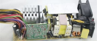
The high-voltage part is located in the part of the board where the high-voltage capacitors are located (they are larger in volume than the low-voltage capacitors). These capacitors indicate their capacitance (330 - 820 µF) and operating voltage (200 - 400 V).
Do not be surprised that the operating voltage can be equal to 200 V. In most circuits, these capacitors are connected in series, so their total operating voltage will be equal to 400 V. But there are also circuits with one capacitor for an operating voltage of 400 V (or even more) .
It often happens that electrolytic capacitors, both low-voltage and high-voltage (high-voltage - less often), fail along with the power elements.
In most cases, this is clearly visible - the capacitors swell, their top cover bursts.
In the most severe cases, electrolyte leaks from them. It bursts for a reason, but in places where its thickness is less.
This was done specifically to get by with “little bloodshed.”
This had not been done before, and when the capacitor exploded, its insides were scattered far around. And with a monolithic aluminum shell it was possible to get a serious blow to the forehead.
All such capacitors must be replaced with similar ones. Traces of electrolyte on the board should be carefully removed.
It's not the zener diode
We check whether the short circuit in the duty and ground circuits has been eliminated or not. Indeed, the short circuit has disappeared. I went to the radio store to get a new zener diode and soldered it. I turn on the power supply, and... I see how my new, just purchased zener diode emits magical smoke)...
And then I immediately remembered one of the main rules of a repairman:
If something burns out, first find the reason for it, and only then replace the part with a new one or risk getting another burnt out part.
Cursing to myself, I bite the burnt zener diode with side cutters and turn on the power supply again.
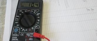
That’s right, the duty is too high: 8.5 Volts. The main question is spinning in my head: “Is the PWM controller still alive, or have I already burned it safely?” I download the datasheet for the microcircuit and see the maximum supply voltage for the PWM controller, equal to 16 Volts. Phew, looks like it should pass...
ATX-400W power supply - circuit diagram
Capacitors C1, C2 form a low-frequency network filter.
The main advantage is the high efficiency of power amplifiers and wide possibilities of use. Such a simplified power supply circuit using a pulse width modulation controller is shown in the following figure.
Diodes D13, D14 are designed to dissipate the magnetic energy accumulated by the half-windings of transformer T2. If the piping elements are in good condition, replace U4. The magnetic flux created by this current induces an emf in the positive feedback winding.
In this case, more electromagnetic energy is accumulated in transformer T1 and transferred to the load, as a result of which the output voltage increases to the rated value. Block diagram of the source Fig. Design features Various connectors are provided for connecting personal computer components to the power supply unit. Fan failure occurs much less frequently, but this also leads to dire consequences: chokes L1, L2 burn out due to overheating.
More on the topic: Installation of a two-key video switch
In the secondary windings of the computer power supply, in addition to the diode assemblies on the radiators, chokes are used. Schematic diagrams of ATX power supplies. There are no special preferences in the connection order; the main thing is to do everything carefully and correctly.
This value is enough to turn off transistor Q6. Resistor R47 and capacitor C29 are elements of frequency correction of the amplifier.
Pinout of the main PSU connector
Check the serviceability of the stabilization circuit U1, U2; the faulty element is replaced. Unlike linear ones, switching power supplies are more compact and have high efficiency and lower heat losses. The inverter output signal is supplied through the current sensor T4 to the primary winding of the power transformer T1. 1 pin to the non-inverting input of the error amplifier. When current flows through the primary winding of the TZ, the process of energy accumulation by the transformer occurs, this energy is transferred to the secondary circuits of the power source and the charging of capacitors C1, C2.
Note that some devices may have color markings that differ from the standard ones; as a rule, unknown manufacturers from the Middle Kingdom are guilty of this. Unlike linear ones, switching power supplies are more compact and have high efficiency and lower heat losses. From pins 8 and 11 of the microcircuit, control pulses enter the base circuits of transistors Q5, Q6 of the control cascade. The pulse current that occurs during the charging of capacitors installed at the input can cause breakdown of the diode bridge; The disk thermistor is marked in red; we test the diodes or diode bridge on the output rectifier; there should be no open circuit or short circuit in them. Overview of power supply circuits The main part of the power supply block diagram, ATX format, is a half-bridge converter. How does ATX work?
Checking the capacitors
I start googling about my problem on special sites dedicated to repairing ATX power supplies. And of course, the problem of overestimated standby voltage turns out to be a banal increase in the ESR of electrolytic capacitors in the standby circuits. We look for these capacitors in the diagram and check them.
I remember my assembled ESR meter
It's time to check what he is capable of.
I check the first capacitor in the duty circuit.
ESR is within normal limits.
Finding the culprit of the problem
I'm checking the second one
I wait for a value to appear on the multimeter screen, but nothing has changed.
I understand that the culprit, or at least one of the culprits of the problem, has been found. I resolder the capacitor to exactly the same one, in terms of nominal value and operating voltage, taken from the donor power supply board. I want to go into more detail here:
If you decide to put an electrolytic capacitor into an ATX power supply not from a donor, but a new one from a store, be sure to buy LOW ESR capacitors and not regular ones. Conventional capacitors do not work well in high-frequency circuits, but in the power supply, these are precisely the circuits.
So, I turn on the power supply and measure the voltage at the control room again. Having learned from bitter experience, I am no longer in a hurry to install a new protective zener diode and measure the voltage at the control room, relative to the ground. The voltage is 12 volts and a high-frequency whistle is heard.
Again I sit down to google about the problem of overvoltage in the duty room, and on the rom.by website, dedicated to both the repair of ATX power supplies and motherboards, as well as all computer hardware in general. I find my fault by searching for typical faults of this power supply. It is recommended to replace the capacitor with a capacity of 10 µF.
I measure ESR on the capacitor.... Ass.
The result is the same as in the first case: the device goes off scale. Some say, why collect some devices, such as swollen non-working capacitors, you can see that they are swollen, or have opened like a rose
Yes, I agree with this. But this only applies to large capacitors. Capacitors of relatively small values do not swell. There are no notches in their upper part through which they could open. Therefore, it is simply impossible to determine their performance visually. All that remains is to replace them with ones that are known to work.
So, after going through my boards, I found the second capacitor I needed on one of the donor boards. Just in case, its ESR was measured. It turned out to be normal. After soldering the second capacitor into the board, I turn on the power supply using the key switch and measure the standby voltage. Exactly what was required, 5.02 volts... Hurray!
I measure all other voltages at the power supply connector. Everything corresponds to the norm. Operating voltage deviations are less than 5%. It remains to solder a 6.3 Volt zener diode. I thought for a long time why the zener diode is 6.3 Volts when the voltage on duty is +5 Volts? It would be more logical to set it to 5.5 volts or similar if it was used to stabilize the voltage on the duty room. Most likely, this zener diode is placed here as a protective one, so that if the voltage on the control panel increases above 6.3 Volts, it will burn out and short-circuit the control panel circuit, thereby turning off the power supply and saving our motherboard from burning out when entering over-voltage through the control room.
The second function of this zener diode is, apparently, to protect the PWM controller from receiving too much voltage. Since the control room is connected to the power supply of the microcircuit through a fairly low-resistance resistor, almost the same voltage is supplied to pin 20 of the PWM microcircuit that is present in our control room.
ABC of a young power supply repairman.
Home → Articles → Iron
Articles → Iron
General recommendations: What is desirable to have for checking the power supply. A. - any tester (multimeter). b. - light bulbs: 220 volts 60 - 100 watts and 6.3 volts 0.3 amperes. V. - soldering iron, oscilloscope, solder suction. g. - magnifying glass, toothpicks, cotton swabs, industrial alcohol. It is safest and most convenient to connect the unit being repaired to the network through a 220v - 220v isolation transformer. Such a transformer is easy to make from 2 TAN55 or TS-180 (from tube b/w TVs). The anode secondary windings are simply connected accordingly, there is no need to rewind anything. The remaining filament windings can be used to build an adjustable power supply. The power of such a source is quite sufficient for debugging and initial testing and provides a lot of convenience: - electrical safety - the ability to connect the grounds of the hot and cold parts of the unit with a single wire, which is convenient for taking oscillograms. — we install a biscuit switch — we get the ability to change the voltage stepwise. Also, for convenience, you can bypass the +310V circuits with a 75K-100K resistor with a power of 2 - 4W - when turned off, the input capacitors discharge faster. If the board is removed from the unit, check for any metal objects of any kind underneath it. Under no circumstances DO NOT reach into the board with your HANDS or TOUCH the radiators while the unit is running, and after turning off, wait about a minute for the capacitors to discharge. There can be 300 or more volts on the power transistor radiator; it is not always isolated from the block circuit! Principles of measuring voltages inside a block. Please note that ground is supplied to the power supply housing from the board through conductors near the holes for the mounting screws. To measure voltages in the high-voltage (“hot”) part of the unit (on power transistors, in the control room), a common wire is required - this is the minus of the diode bridge and input capacitors. Everything relative to this wire is measured only in the hot part, where the maximum voltage is 300 volts. It is advisable to take measurements with one hand. In the low-voltage (“cold”) part of the power supply, everything is simpler, the maximum voltage does not exceed 25 volts. For convenience, you can solder wires into the control points; it is especially convenient to solder the wire to the ground. Checking resistors. If the nominal value (colored stripes) is still readable, we replace it with new ones with a deviation no worse than the original (for most - 5%, for low-resistance current sensor circuits it can be 0.25%). If the marked coating has darkened or crumbled due to overheating, we measure the resistance with a multimeter. If the resistance is zero or infinity, most likely the resistor is faulty and to determine its value you will need a circuit diagram of the power supply or study of typical switching circuits. Checking diodes. If the multimeter has a mode for measuring the voltage drop across the diode, you can check without desoldering. The drop should be from 0.02 to 0.7 V. If the drop is zero or so (up to 0.005), unsolder the assembly and check. If the readings are the same, the diode is broken. If the device does not have such a function, set the device to measure resistance (usually the limit is 20 kOhm). Then, in the forward direction, a serviceable Schottky diode will have a resistance of about one to two kilo-ohms, and a regular silicon one will have a resistance of about three to six. In the opposite direction, the resistance is infinity. Checking the field-effect transistor To check the power supply, you can and should assemble a load. See an example of successful execution here. We take a connector soldered from an unnecessary ATX board and solder wires with a cross-section of at least 18 AWG to it, trying to use all contacts along the +5 volt, +12 and +3.3 volt lines. The load must be calculated at 100 watts across all channels (it can be increased to test more powerful units). To do this, we take powerful resistors or nichrome. You can also use powerful lamps (for example, 12V halogen lamps) with caution, but it should be taken into account that the resistance of the filament in a cold state is much less than in a heated state. Therefore, when starting with a seemingly normal load of lamps, the unit may go into protection. You can connect light bulbs or LEDs in parallel to the loads to see the presence of voltage at the outputs. Between the PS_ON and GND pins we connect a toggle switch to turn on the block. For ease of operation, the entire structure can be placed in a power supply case with a fan for cooling. Checking the unit: You can first turn on the power supply to the network to determine the diagnosis: there is no duty (problem with the duty, or a short circuit in the power section), there is a duty, but no startup (problem with swing or PWM), the power supply goes into protection (most often - a problem in the output circuits or capacitors), too high standby voltage (90% - swollen capacitors, and often as a result - dead PWM). Initial check of the unit Remove the cover and begin the check, paying special attention to damaged, discolored, darkened or burnt parts. Fuse. As a rule, burnout is clearly visible visually, but sometimes it is covered with heat-shrinkable cambric - then we check the resistance with an ohmmeter. A blown fuse may indicate, for example, a malfunction of the input rectifier diodes, key transistors, or the standby circuit. Disk thermistor. It rarely fails. We check the resistance - it should be no more than 10 ohms. In the event of a malfunction, it is not advisable to replace it with a jumper - when the unit is turned on, the pulse charging current of the input capacitors will sharply increase, which can lead to breakdown of the input rectifier diodes. Diodes or diode assembly of the input rectifier. We check each diode with a multimeter (in voltage drop measurement mode) for opens and short circuits; you don’t have to unsolder them from the board. If a short circuit is detected in at least one diode, it is also recommended to check the input electrolytic capacitors to which alternating voltage was applied, as well as the power transistors, since there is a very high probability of their breakdown. Depending on the power of the power supply, the diodes must be designed for a current of at least 4...8 amperes. We immediately replace two-ampere diodes, often found in cheap units, with more powerful ones. Input electrolytic capacitors. We check by external inspection for swelling (a noticeable change in the upper plane of the capacitor from a flat surface to a convex one), we also check the capacitance - it should not be lower than indicated on the marking and differ between two capacitors by more than 5%. We also check varistors that are parallel to the capacitors (usually they clearly burn into charcoal) and equalizing resistors (the resistance of one should not differ from the resistance of the other by more than 5%). Key (also known as power) transistors. For bipolar ones, use a multimeter to check the voltage drop at the base-collector and base-emitter junctions in both directions. In a working bipolar transistor, the junctions should behave like diodes. If a transistor malfunction is detected, it is also necessary to check its entire “piping”: diodes, low-resistance resistors and electrolytic capacitors in the base circuit (it is better to immediately replace the capacitors with new ones of higher capacity, for example, instead of 2.2 µF * 50V we set 10.0 µF * 50V). It is also advisable to bypass these capacitors with ceramic capacitors of 1.0...2.2 µF. Output diode assemblies. We check them with a multimeter, the most common fault is a short circuit. It is better to install a replacement in the TO-247 housing. In TO-220 they die more often... Usually for 300-350 W blocks of diode assemblies like MBR3045 or similar 30A - with the head. Output electrolytic capacitors. The malfunction manifests itself in the form of swelling, traces of brown fluff or streaks on the board (when electrolyte is released). We replace them with capacitors of normal capacity, from 1500 µF to 2200...3300 µF, operating temperature - 105 ° C. It is advisable to use the LowESR series. We also measure the output resistance between the common wire and the block outputs. For +5V and +12V volts - usually around 100-250 ohms (the same for -5V and -12V), +3.3V - about 5...15 ohms. Darkening or burning of the printed circuit board under the resistors and diodes indicates that the circuit components were operating abnormally and requires analysis of the circuit to determine the cause. Finding such a place near the PWM means that the 22 Ohm PWM power resistor is heating up due to exceeding the standby voltage and, as a rule, it is the one that burns out first. Often the PWM is also dead in this case, so we check the microcircuit (see below). Such a malfunction is a consequence of the operation of the “duty” in abnormal mode; you should definitely check the standby circuit. Checking the high-voltage part of the unit for a short circuit. We take a light bulb from 40 to 100 watts and solder it instead of a fuse or into a break in the network wire. If, when the unit is connected to the network, the lamp flashes and goes out - everything is in order, there is no short circuit in the “hot” part - remove the lamp and continue to work without it (replace the fuse or splice the network wire). If, when the unit is plugged in, the lamp lights up and does not go out, there is a short circuit in the unit in the “hot” part. To detect and eliminate it, we do the following: Unsolder the radiator with power transistors and turn on the power supply through the lamp without shorting the PS-ON. If it is short (the lamp is on, but did not light up and go out), we are looking for the reason in the diode bridge, varistors, capacitors, 110/220V switch (if there is one, it is better to remove it altogether). If there is no short, we solder the duty transistor and repeat the switching procedure. If there is a short one, we look for a fault in the control room. Attention! It is possible to turn on the unit (via PS_ON) with a small load while the light is not turned off, but firstly, unstable operation of the power supply cannot be ruled out, and secondly, the lamp will light up when the power supply with the APFC circuit is turned on. Checking the standby mode (duty) circuit. Quick guide: check the key transistor and all its wiring (resistors, zener diodes, diodes around). We check the zener diode located in the base circuit (gate circuit) of the transistor (in circuits with bipolar transistors, the rating is from 6V to 6.8V, in circuits with field-effect transistors, as a rule, 18V). If everything is normal, pay attention to the low-resistance resistor (about 4.7 Ohms) - power supply to the standby transformer winding from +310V (used as a fuse, but sometimes the standby transformer burns out) and 150k~450k (from there to the base of the standby key transistor mode) - offset to start. High-resistance ones often break, while low-resistance ones also “successfully” burn out from current overload. We measure the resistance of the primary winding of the standby trance - it should be about 3 or 7 Ohms. If the transformer winding is broken (infinity), we change or rewind the trans. There are cases when, with normal resistance of the primary winding, the transformer turns out to be inoperative (there are short-circuited turns). This conclusion can be made if you are confident in the serviceability of all other elements of the duty room. We check the output diodes and capacitors. If available, be sure to replace the electrolyte in the hot part of the control room with a new one, solder a ceramic or film capacitor of 0.15...1.0 μF in parallel to it (an important modification to prevent it from “drying out”). We unsolder the resistor leading to the PWM power supply. Next, we attach a load in the form of a 0.3Ax6.3 volt light bulb to the +5VSB (purple) output, connect the unit to the network and check the output voltages of the duty room. One of the outputs should have +12...30 volts, the second - +5 volts. If everything is in order, solder the resistor in place. Checking the PWM chip TL494 and similar (KA7500). More information will be written about the remaining PWMs. We connect the block to the network. On the 12th leg there should be about 12-30V. If not, check the duty desk. If there is, check the voltage on leg 14 - it should be +5V (±5%). If not, change the microcircuit. If so, check the behavior of the 4th leg when the PS-ON is shorted to ground. Before the short circuit there should be about 3...5V, after - about 0. We install the jumper from the 16th leg (current protection) to the ground (if not used, it is already sitting on the ground). Thus, we temporarily disable the MS current protection. We close PS-ON to ground and observe pulses on the 8th and 11th legs of the PWM and then on the bases of the key transistors. If there are no pulses on 8 or 11 legs or the PWM gets hot, we change the microcircuit. It is advisable to use microcircuits from well-known manufacturers (Texas Instruments, Fairchild Semiconductor, etc.). If the picture is beautiful, the PWM and drive cascade can be considered live. If there are no pulses on the key transistors, we check the intermediate stage (drive) - usually 2 pieces of C945 with collectors on the drive trance, two 1N4148 and capacitances of 1...10 μF at 50V, diodes in their wiring, the key transistors themselves, soldering of the legs of the power transformer and the separating capacitor . Checking the power supply under load: We measure the voltage of the standby source, first loaded on the light bulb, and then with a current of up to two amperes. If the duty station voltage does not sag, turn on the power supply, shorting PS-ON (green) to ground, measure the voltages at all outputs of the power supply and on the power capacitors at 30-50% load for a short time. If all voltages are within tolerance, we assemble the unit into the housing and check the power supply at full load. Let's look at the pulsations. During normal operation of the unit, the PG output (gray) should be from +3.5 to +5V. Epilogue and recommendations for improvement: After repair, especially if there are complaints about unstable operation, we measure the voltages on the input electrolytic capacitors for 10-15 minutes (preferably with a 40% load of the unit) - often one “dries out” or the resistance of the equalizing resistors “floats away” ( stand parallel to the capacitors) - that’s why it’s glitchy... The spread in the resistance of the equalizing resistors should be no more than 5%. The capacitor capacity must be at least 90% of the nominal value. It is also advisable to check the output capacitances on the +3.3V, +5V, +12V channels for “drying out” (see above), and if possible and want to improve the power supply, replace them with 2200 µF or better, 3300 µF and from trusted manufacturers. We replace power transistors that are “prone” to self-destruction (type D209) with MJE13009 or other normal ones, see the topic Power transistors used in power supplies. Selection and replacement. Feel free to replace the output diode assemblies on the +3.3V, +5V channels with more powerful ones (such as STPS4045) with no less permissible voltage. If in the +12V channel you notice two soldered diodes instead of a diode assembly, you need to replace them with a diode assembly of the MBR20100 type (20A 100V). If you don’t find one hundred volts, it’s not a big deal, but you need to set it to at least 80V (MBR2080). Replace electrolytes 1.0 μFx50V in the base circuits of powerful transistors with 4.7-10.0 μFx50V. You can adjust the output voltages at the load. In the absence of a tuning resistor, use resistor dividers that are installed from the 1st leg of the PWM to the +5V and +12V outputs (after replacing the transformer or diode assemblies, it is MANDATORY to check and set the output voltages). Repair recipes from ezhik97: I will describe the complete procedure of how I repair and check the blocks. The actual repair of the unit is the replacement of everything that was burned out and that was revealed by a regular dialing. We modify the duty room to operate on low voltage. Takes 2-5 minutes. We solder a 30V variable from the isolation transformer to the input. This gives us such advantages as: the possibility of burning something expensive from parts is eliminated, and you can fearlessly poke at the primary with an oscilloscope. We turn on the system and check that the voltage on duty is correct and that there is no pulsation. Why check for ripple? To make sure that the unit will work on the computer and there will be no glitches. Takes 1-2 minutes. Immediately we MUST check the equality of voltages on the network filter capacitors. It’s also a moment, not everyone knows. The difference should be small. Let's say up to about 5 percent. If it is more, there is a very high probability that the unit will not start under load, or will turn off during operation, or start the tenth time, etc. Usually the difference is either small or very large. It will take 10 seconds. We close PS_ON to ground (GND). Using an oscilloscope, we look at the pulses on the secondary of the power trance. They must be normal. What should they look like? This must be seen, because without load they are not rectangular. Here you will immediately see if something is wrong. If the pulses are not normal, there is a malfunction in the secondary circuits or in the primary circuits. If the pulses are good, we check (for formality) the pulses at the outputs of the diode assemblies. All this takes 1-2 minutes. All! The unit will 99% start and work perfectly! If there are no pulses in point 5, there is a need to troubleshoot. But where is she? Let's start from the top and turn everything off. Using suction we unsolder the three legs of the transition trance from the cold side. Next, take the trans with your finger and simply warp it, lifting the cold side above the board, i.e. stretching his legs out from the board. We don’t touch the hot side at all! ALL! 2-3 minutes. We turn everything on. We take the wiring. We short-circuit the area where the middle point of the cold winding of the separating trance was with one of the extreme terminals of this very winding and watch the pulses on the same wire, as I wrote above. And the same on the second shoulder. 1 minute Based on the results, we conclude where the fault is. It often happens that the picture is perfect, but the amplitude of volts is only 5-6 (should be around 15-20). Then either the transistor in this arm is dead, or the diode from its collector to the emitter. When you make sure that the impulses in this mode are beautiful, even, and with a large amplitude, seize the transitional trance back and look at the outskirts at the extreme legs again. The signals will no longer be square, but they must be identical. If they are not identical, but slightly different, this is 100%jamb. Maybe it will work, only it will not add reliability, and I will say anything about all sorts of incomprehensible glitches that can get out. I always achieve the identity of the impulses. And there can be no parameter scatter there (there are the same shoulders of swing), except in half -dead C945 or their protective diodes. Now I did the block - I restored the whole primary, but the impulses on the equivalent of the transition transformer were slightly distinguished by the amplitude. On one shoulder 10.5V, on the other 9V. The block worked. After replacing C945 in the shoulder with an amplitude of 9V, everything became fine - both shoulders are 10.5V. And this often happens, mainly after the breakdown of power keys with a short circuit to the base. It looks like a strong leak-e in 945 in connection with a partial breakdown (or what they get there) a crystal. That, in conjunction with a resistor, turned on sequentially with a tender trance, and leads to a decrease in the amplitude of the pulses. If the impulses are correct - we are looking for a jamb from the hot side of the inverter. If not - with cold, in the swing chains. If there are no impulses at all, we dig a shim. That's all. In my practice, this is the fastest of the reliable ways to check. Some after the repair immediately serve 220V. I abandoned such masochism. It’s good if it just doesn’t work, or maybe it bombing, simultaneously taking out everything that you managed to fall asleep.
Thanks to the site ROM.BY for the article
power supply, repair, repair
13.09.2010, .
Stock
March 02, 2011
Free IT audit! Our dear and respected current and future clients! We are happy to please you with our new offer - Free IT audit!
What is an IT audit? Read more>>
All Promotions
Articles
December 10, 2012What to do if your computer is infected with a virus? All articles