High voltage as a way to reduce losses
The reality is that transmitting electricity over long distances is inevitably accompanied by losses. A significant part of the electricity, passing from the generator at the power plant to the outlet of the household consumer, turns into heat and is spent on heating the atmosphere. However, this does not reduce the cost of generating electricity, so the end user still has to pay for these non-target costs.
The following methods allow you to reduce unnecessary losses, respectively, expenses:
- use of high-temperature superconductors;
- increasing the cross-section of cables and wires of power lines;
- increase in voltage in transmission lines.
The first method is the future. However, today it is technically infeasible. The second was abandoned in the first couple of years of development of the electric power industry, because it is not economically feasible due to the extra costs of thickening the conductors. The use of high voltage has proven to be the most successful method, which is why it has been used around the world for about a hundred years.
Transmission principle
Electricity is transmitted due to the generation and transmission of current. It, in turn, is formed due to tension. Power is the product of voltage and electric current. Therefore, as the voltage increases, it is necessary to reduce the transmitted current and reduce the wire cross-section, which is necessary to transmit this power and reduce the cost of the line.
Transmission principle
Classification of power lines
Wireless power transmission
There are many types of power lines. Each type is tailored to its specific needs and tasks. In accordance with this, the PUE regulates the following classification of overhead power lines.
According to the voltage class of power lines there are:
- low voltage, up to 1 kV;
- high voltage, over 1 kV.
By purpose:
- Intersystem lines with voltage from 500 kV and above;
- Main lines, 220-500 kV;
- Distribution, 110-220 kV;
- 35 kV lines for powering agricultural consumers;
- 1-20 kV power lines used within one populated area.
The type of electric current in power lines is divided into:
- variable (almost all lines);
- direct current (rarely found, mainly 3.3 kV railway contact network).
Types and structure of losses
Losses mean the difference between the electricity supplied to consumers and the energy actually received by them. To normalize losses and calculate their actual value, the following classification was adopted:
- Technological factor. It directly depends on characteristic physical processes, and can change under the influence of the load component, semi-fixed costs, as well as climatic conditions.
- Costs spent on operating auxiliary equipment and providing the necessary conditions for the work of technical personnel.
- Commercial component. This category includes errors in metering devices, as well as other factors causing under-metering of electricity.
Approximate structure of losses
As can be seen from the graph, the highest costs are associated with transmission via overhead lines (power lines), this amounts to about 64% of the total number of losses. In second place is the corona effect (ionization of air near the overhead line wires and, as a consequence, the occurrence of discharge currents between them) – 17%.
Corona discharge on a power line insulator
Based on the presented graph, it can be stated that the largest percentage of non-targeted expenses falls on the technological factor.
Methods of transmitting electricity
Determination of power quality by analyzers
The most common two methods of transmitting electricity are using overhead and cable lines. They differ from each other in range and environment in which the conductor is located.
Overhead lines are, simply put, copper or aluminum conductors suspended through insulators on metal or reinforced concrete supports. With this method, it is possible to transmit electricity over long distances and between different countries.
Cable line - laying wires underground. Individual current-carrying conductors are located, as a rule, in rubber or PVC insulation. If the voltage is high, then there is also armor made of metal tape. It also serves as a shield against interference. It is found mainly within the city or enterprise.
Cable routing
Additional Information. Using cable lines, it is possible to transport electricity along the bottom of reservoirs and even seas. This allows electricity to be supplied to the islands. The use of power lines does not imply such possibilities.
Electricity transportation route
So, as we have already said, the starting point is the power station, which, in fact, generates electricity. Today, the main types of power plants are hydro (hydroelectric power plants), thermal power plants (thermal power plants) and nuclear power plants (nuclear power plants). In addition, there are solar, wind and geothermal electricity. stations.
Next, electricity is transmitted from the source to consumers, who may be located over long distances. To transmit electricity, you need to increase the voltage using step-up transformers (the voltage can be increased up to 1150 kV, depending on the distance).
Why is electricity transmitted at increased voltage? Everything is very simple. Let's remember the formula for electrical power - P=UI, then if you transfer energy to the consumer, then the higher the voltage on the power line, the less current in the wires, with the same power consumption. Thanks to this, it is possible to build power lines with high voltage, reducing the cross-section of the wires, compared to power lines with lower voltage. This means that construction costs will be reduced - the thinner the wires, the cheaper they are.
Accordingly, electricity is transferred from the station to a step-up transformer (if necessary), and after that, with the help of power lines, electricity is transferred to the central distribution substations (central distribution substations). The latter, in turn, are located in cities or close to them. At the central distribution point, the voltage is reduced to 220 or 110 kV, from where the electricity is transmitted to substations.
Next, the voltage is reduced again (to 6-10 kV) and the electrical energy is distributed among transformer points, also called transformer substations. Electricity can be transmitted to transformer points not via power lines, but by an underground cable line, because in urban environments this will be more appropriate. The fact is that the cost of rights-of-way in cities is quite high and it will be more profitable to dig a trench and lay a cable in it than to take up space on the surface.
From transformer points, electricity is transmitted to multi-storey buildings, private sector buildings, garage cooperatives, etc.
We draw your attention to the fact that at the transformer substation the voltage is reduced once again, to the usual 0.4 kV (380 volt network)
If we briefly consider the route for transmitting electricity from the source to consumers, it looks like this: power plant (for example, 10 kV) - step-up transformer substation (from 110 to 1150 kV) - power lines - step-down transformer substation - transformer substation (10-0.4 kV) – residential buildings.
This is how electricity is transmitted through wires to our home. As you can see, the scheme for transmitting and distributing electricity to consumers is not too complicated, it all depends on how long the distance is.
You can clearly see how electrical energy enters cities and reaches the residential sector in the picture below:
Experts talk about this issue in more detail:
How electricity moves from source to consumer
Scheme of energy transfer from power plant to consumer
Electricity consumption of household appliances
The main power plant (1) produces a voltage of about 10-12 kV. It is then raised by transformer (2) to a higher level: 35, 110, 220, 400, 500 or 1150 kV. Then, via a cable or overhead line (3), the energy is transmitted over distances from units to thousands of kilometers and reaches a step-down substation. It also has a transformer (4) installed on it, which converts hundreds of kilovolts back into 10-12 thousand volts. This is followed by another step-down stage to 380/220 V (5). This voltage is final and is distributed to consumers (6), i.e. residential buildings, hospitals, etc.
Transportation of electrical energy
Transmission of electricity without wires - from the beginning to the present day
Wireless transmission of electricity is a method of transmitting electrical energy without the use of conductive elements in an electrical circuit.
At the end of the 19th century, the discovery that electricity could make a light bulb glow sparked an explosion of research to find the best way to transmit electricity.
Wireless energy transfer was actively studied at the beginning of the 20th century, when scientists paid great attention to finding various ways to wirelessly transfer energy. The goal of the research was simple - to generate an electric field in one place so that it could then be detected by instruments at a distance. At the same time, attempts were made to supply energy at a distance not only to highly sensitive sensors for recording voltage, but also to significant energy consumers. So, in 1904 at the exhibition St. Louis World's Fair was awarded a prize for successfully starting a 0.1 horsepower aircraft engine at a distance of 30 m.
The gurus of “electricity” are known to many (William Sturgeon, Michael Faraday, Nicolas Joseph Callan, James Clerk Maxwel, Heinrich Hertz, Mahlon Loomas, etc.), but few people know that the Japanese researcher Hidetsugu Yagi used an antenna of his own design to transmit energy. In February 1926, he published the results of his research, in which he described the structure and method of tuning the Yagi antenna.
Note: I deliberately did not mention Nikola Tesla: a lot has been written by many.
Very serious work and projects were carried out in the USSR in the period 1930-1941 and in parallel in Drittes Reich. Naturally, mainly for military purposes. Naturally, mainly for military purposes: defeating enemy personnel, destroying military and industrial infrastructure, etc. In the USSR, serious work was also carried out on the use of microwave radiation to prevent surface corrosion of metal structures and products. But that's a different story. Again we have to climb into the dusty attic.
One of the greatest Russian physicists of the last century, Nobel Prize laureate, Academician Pyotr Leonidovich Kapitsa devoted part of his creative biography to the study of the prospects for using microwave oscillations and waves to create new and highly efficient energy transmission systems. In 1962, in the preface to his book, he wrote
“... I want to remind you that electrical engineering, before coming to the service of the energy sector, in the last century dealt extensively only with issues of telecommunications (telegraph, signaling, etc.). It is likely that history will repeat itself: electronics are now used primarily for radio communications, but their future lies in solving the biggest energy problems."
.
Of the long list of fantastic technical ideas realized in the twentieth century, only the dream of wireless transmission of electrical energy continued to remain unrealized. Detailed descriptions of energy beams in science fiction novels tantalized engineers with their obvious need, yet the practical difficulty of implementing them. But the situation gradually began to change for the better.
In 1964, microwave electronics expert William C. Brown first tested a device (a helicopter model) capable of receiving and using microwave beam energy in the form of direct current, thanks to an antenna array consisting of half-wave dipoles, each loaded with highly efficient Schottky diodes.
In 1964, William C. Brown demonstrated his helicopter model on the CBS program Walter Cronkite News, which received sufficient energy for flight from a microwave emitter.
Already by 1976, William Brown transmitted a microwave beam of 30 kW power over a distance of 1.6 km with an efficiency exceeding 80%.
Tests were carried out in the laboratory and commissioned by Raytheon Co. Read in detail (in English): Microwave Power Transmission - IOSR Journals The microwave powered Helicopter. William C. Brown. Raytheon Company.
In 1968, American space research specialist Peter E. Glaser proposed placing large solar panels in geostationary orbit, and transmitting the energy they generate (5-10 GW) to the surface of the Earth with a well-focused beam of microwave radiation , then convert it into direct or alternating current energy of technical frequency and distribute it to consumers.
This scheme made it possible to use the intense flux of solar radiation existing in geostationary orbit (~ 1.4 kW/sq.m.) and transmit the resulting energy to the Earth’s surface continuously, regardless of the time of day and weather conditions [2-12]. Due to the natural inclination of the equatorial plane to the ecliptic plane with an angle of 23.5 degrees, a satellite located in a geostationary orbit is illuminated by the flow of solar radiation almost continuously, with the exception of short periods of time near the days of the spring and autumn equinoxes, when this satellite falls into the Earth's shadow. These periods of time can be accurately predicted, and in total they do not exceed 1% of the total length of the year.
The frequency of electromagnetic oscillations of the microwave beam must correspond to those ranges that are allocated for use in industry, scientific research and medicine. If this frequency is chosen to be 2.45 GHz, then meteorological conditions, including thick clouds and intense precipitation, have virtually no effect on the efficiency of power transmission. The 5.8 GHz band is attractive because it offers the opportunity to reduce the size of the transmit and receive antennas. However, the influence of meteorological conditions here requires additional study.
The current level of development of microwave electronics allows us to speak of a fairly high efficiency of microwave energy transfer by a microwave beam from geostationary orbit to the Earth's surface - about 70-75%. In this case, the diameter of the transmitting antenna is usually chosen to be 1 km, and the ground rectenna has dimensions of 10 km x 13 km for a latitude of 35 degrees. A SCES with an output power level of 5 GW has a radiated power density at the center of the transmitting antenna of 23 kW/sq.m., and at the center of the receiving antenna – 230 W/sq.m.
Various types of solid-state and vacuum microwave generators for the SKES transmitting antenna were investigated. William Brown showed, in particular, that magnetrons, well-developed by industry, intended for microwave ovens, can also be used in transmitting antenna arrays of SKES, if each of them is equipped with its own negative feedback circuit in phase with respect to the external synchronizing signal (so called Magnetron Directional Amplifier - MDA).
Rectenna is a highly efficient receiving-converting system, however, the low-voltage diodes and the need for their serial switching can lead to avalanche-like breakdowns. A cyclotron energy converter can largely eliminate this problem.
The SKES transmitting antenna can be a back-reradiating active antenna array based on slot waveguides. Its rough orientation is carried out mechanically; for precise guidance of the microwave beam, a pilot signal is used, emitted from the center of the receiving rectenna and analyzed on the surface of the transmitting antenna by a network of appropriate sensors.
From 1965 to 1975 A scientific program led by Bill Brown was successfully completed, demonstrating the ability to transmit 30 kW of power over a distance of more than 1 mile with an efficiency of 84%.
In 1978–1979 in the United States, under the leadership of the Department of Energy (DOE) and NASA (NASA), the first government research program aimed at determining the prospects of SCES was carried out.
In 1995–1997, NASA again returned to discussing the prospects of SCES, based on the technological progress achieved by that time.
Research continued in 1999–2000 (Space Solar Power (SSP) Strategic Research & Technology Program).
The most active and systematic research in the field of SCES was carried out by Japan. In 1981, under the leadership of Professors M. Nagatomo and S. Sasaki at the Space Research Institute of Japan, research began on the development of a prototype SCES with a power level of 10 MW, which could be created using existing launch vehicles. The creation of such a prototype allows one to accumulate technological experience and prepare the basis for the formation of commercial systems.
The project was named SKES2000 (SPS2000) and received recognition in many countries around the world.
In 2008, Marin Soljačić, assistant professor of physics at the Massachusetts Institute of Technology (MIT), was awakened from a sweet sleep by the persistent beeping of his cell phone. “The phone didn’t stop talking, demanding that I put it on charge,” Soljacic says. Tired and not about to get up, he began to dream that the phone, once at home, would start charging on its own
.
This is how WiTricity and WiTricity corporation appeared.
In June 2007, Marin Soljačić and several other MIT researchers reported the development of a system in which a 60 W light bulb was supplied from a source located 2 m away, with an efficiency of 40%.
According to the authors of the invention, this is not a “pure” resonance of coupled circuits and not a Tesla transformer with inductive coupling. The radius of energy transmission today is a little more than two meters, in the future - up to 5-7 meters. In general, scientists tested two fundamentally different schemes. 1. In an induction coil or electrical transformer, which has a metal or air core, the transfer of energy is carried out by a simple electromagnetic connection called magnetic induction.
Using this method, transmitting and receiving energy became feasible over a considerable distance, but to obtain significant voltage in this way it was necessary to place the two coils very close. 2. If magnetic resonance coupling is used, where both inductors are tuned to mutual frequency, significant energy can be transferred over a considerable distance. Similar technologies are being feverishly developed by other companies: Intel demonstrated its WREL technology with energy transfer efficiency of up to 75%. In 2009, Sony demonstrated the operation of a TV without a network connection. There is only one circumstance that is alarming: regardless of the transmission method and technical tricks, the energy density and field strength in the premises must be high enough to power devices with a power of several tens of watts. According to the developers themselves, there is no information yet on the biological effects of such systems on humans. Considering the recent emergence and different approaches to the implementation of energy transfer devices, such research is yet to come, and the results will not appear soon. And we can judge their negative impact only indirectly. Something will again disappear from our homes, such as cockroaches.
In 2010, Haier Group, a Chinese home appliance manufacturer, unveiled its unique product at CES 2010 - a completely wireless LCD TV based on the research of Professor Marin Soljacic on wireless power transmission and wireless home digital interface (WHDI).
In 2012-2015 Engineers at the University of Washington have developed technology that allows Wi-Fi to be used as an energy source to power portable devices and charge gadgets. The technology has already been recognized by Popular Science magazine as one of the best innovations of 2015. The ubiquity of wireless data transmission technology in itself has produced a real revolution. And now it’s the turn of wireless energy transmission over the air, which developers from the University of Washington called PoWiFi (from Power Over WiFi).
During the testing phase, the researchers were able to successfully charge small-capacity lithium-ion and nickel-metal hydride batteries. Using the Asus RT-AC68U router and several sensors located at a distance of 8.5 meters from it. These sensors convert the energy of the electromagnetic wave into direct current with a voltage of 1.8 to 2.4 volts, which is necessary to power microcontrollers and sensor systems. The peculiarity of the technology is that the quality of the working signal does not deteriorate. You just need to reflash the router, and you can use it as usual, plus supply power to low-power devices. In one demonstration, a small, low-resolution surveillance camera located more than 5 meters from the router was successfully powered. Then the Jawbone Up24 fitness tracker was charged to 41%, which took 2.5 hours.
To tricky questions about why these processes do not negatively affect the quality of the network communication channel, the developers answered that this becomes possible due to the fact that the re-flashed router, during its operation, sends energy packets through channels unoccupied by information transmission. They came to this decision when they discovered that during periods of silence, energy simply flows out of the system, but it can be used to power low-power devices.
During the research, the PoWiFi system was placed in six houses, and residents were asked to use the Internet as usual. Load web pages, watch streaming videos, and then tell us what's changed. As a result, it turned out that network performance did not change at all. That is, the Internet worked as usual, and the presence of the added option was not noticeable. And these were only the first tests, when a relatively small amount of energy was collected over Wi-Fi
.
In the future, PoWiFi technology could well serve to power sensors built into household appliances and military equipment in order to control them wirelessly and carry out remote charging/recharging.
Current is the transfer of energy for UAVs (most likely using PoWiMax technology or from the radar of the carrier aircraft):
→ LOCUST - Swarming Navy Drones → The Pentagon successfully tested a swarm of 103 drones → Intel operated the drone show during Lady Gaga's Super Bowl halftime performance
For a UAV, the negative from the inverse square law (isotropically radiating antenna) is partially “compensated” by the antenna beamwidth and radiation pattern:
After all, an aircraft's radar can produce 17 kW of EMP energy in a pulse.
This is not cellular communication - where the cell must provide 360-degree communication to the end elements. Let's assume this variation: The carrier aircraft (for Perdix) this F-18 has (now) AN/APG-65 radar:
maximum average radiated power of 12000 W
or in the future it will have AN/APG-79 AESA: in a pulse it should produce EMP energy under 15 kW
This is quite enough to extend the active life of Perdix Micro-Drones from the current 20 minutes to an hour, and maybe more.
Most likely, an intermediate Perdix Middle drone will be used, which will be irradiated at a sufficient distance by the fighter's radar, and it, in turn, will “distribute” energy to the younger brothers of the Perdix Micro-Drones via PoWiFi/PoWiMax, while simultaneously exchanging information with them (flight, aerobatic, target tasks, swarm coordination).
Perhaps soon it will come to charging cell phones and other mobile devices that are within the range of Wi-Fi, Wi-Max or 5G?
Afterword: 10-20 years, after the widespread introduction of numerous electromagnetic microwave emitters into everyday life (Mobile phones, Microwave ovens, Computers, WiFi, Blu tools, etc.), suddenly cockroaches in big cities suddenly turned into a rarity! Now the cockroach is an insect that can only be found in a zoo. They suddenly disappeared from the homes they once loved so much.
COCKROACHES CARL! These monsters, leaders of the list of “radioresistant organisms,” shamelessly capitulated!
LD 50 is the average lethal dose, that is, the dose kills half of the organisms in the experiment; LD 100 - a lethal dose kills all organisms in the experiment.
Who's next in line?
The permissible levels of radiation from mobile communication base stations (900 and 1800 MHz, total level from all sources) in sanitary and residential areas in some countries differ markedly: Ukraine: 2.5 µW/cm².
(the most stringent sanitary standard in Europe) Russia, Hungary: 10 µW/cm². Moscow: 2.0 µW/cm². (the norm existed until the end of 2009) USA, Scandinavian countries: 100 μW/cm². The temporary permissible level (TLA) from mobile radiotelephones (MRT) for radiotelephone users in the Russian Federation is determined to be 10 μW/cm² (Section IV - Hygienic requirements for mobile land radio communication stations SanPiN 2.1.8/2.2.4.1190-03 “Hygienic requirements for placement and operation means of land mobile radio communications"). In the USA, the Certificate is issued by the Federal Communications Commission (FCC) for cellular devices whose maximum SAR level does not exceed 1.6 W/kg (and the absorbed radiation power is reduced to 1 gram of human organ tissue). In Europe, according to the international directive of the Commission on Non-Ionizing Radiation Protection (ICNIRP), the SAR value of a mobile phone should not exceed 2 W/kg (the absorbed radiation power is reduced to 10 grams of human organ tissue). More recently, in the UK, a safe SAR level was considered to be 10 W/kg. A similar picture was observed in other countries. The maximum SAR value adopted in the standard (1.6 W/kg) cannot even be confidently attributed to “hard” or “soft” standards. The standards adopted in both the USA and Europe for determining the value of SAR (all regulation of microwave radiation from cell phones, which is discussed, is based only on the thermal effect, that is, associated with heating the tissues of human organs). COMPLETE CHAOS.
Medicine has not yet given a clear answer to the question: is mobile/WiFi harmful and to what extent? What will happen to the wireless transmission of electricity using microwave technologies? Here the power is not watts and miles of watts, but kW...
Note: A typical WiMAX base station emits power at approximately +43 dBm (20 W), and a mobile station typically transmits at +23 dBm (200 mW).
Documents, photos and videos used
"JOURNAL OF RADIO ELECTRONICS" N 12, 2007 (ELECTRIC POWER FROM SPACE - SOLAR SPACE POWER PLANTS, V. A. Vanke) "Microwave electronics - prospects in space energy" V. Vanke, Doctor of Physical and Mathematical Sciences. www.nasa.gov www.whdi.org www.defense.gov www.witricity.com www.ru.pinterest.com www.raytheon.com www.ausairpower.net www.wikipedia.org www.slideshare.net www.homes .cs.washington.edu www.dailywireless.org www.digimedia.ru www.powercoup.by www.researchgate.net www.proelectro.info www.youtube.com
Transformer substations
Transformer substations are used to convert voltage from one value to another. They are a fenced facility that has a transformer on its territory. Inside it are the primary and secondary windings (coils). Their electromagnetic interaction allows energy to be converted with high efficiency. Overhead lines or cables enter the substation with one voltage and exit with another, usually lower.
A step-down transformer
All kinds of electricity control and metering systems and switchgear (RU) are also located there. It is intended for communication with other objects of the power system and is an integral part of the transformer substation. The switchgear allows you to disconnect an individual consumer on the low voltage side without de-energizing everyone else.
Real projects today
In all recent years, according to the above technologies, scientists have tried and are trying to implement only two projects.
The first of them started out very encouragingly. In the 2000s, on Reunion Island, a need arose for the constant transmission of 10 kW of power over a distance of 1 km.
The mountainous terrain and local vegetation did not allow the laying of overhead power lines or cables there.
All movements on the island to this point were carried out exclusively by helicopters.
To solve the problem, the best minds from different countries were gathered into one team. Including those previously mentioned in the article, our scientists from Moscow State University V. Vanke and V. Savin.
However, at the moment when the practical implementation and construction of energy transmitters and receivers should have begun, the project was frozen and stopped. And with the onset of the crisis in 2008, they completely abandoned it.
In fact, this is very disappointing, since the theoretical work done there was colossal and worthy of implementation.
The second project looks crazier than the first. However, real funds are allocated for it. The idea itself was expressed back in 1968 by US physicist P. Glaser.
He proposed an idea that was not entirely normal at that time - to launch a huge satellite into geostationary orbit 36,000 km above the earth. Place solar panels on it that will collect free energy from the sun.
Then all this should be converted into a beam of microwave waves and transmitted to the ground.
A sort of “death star” in our earthly realities.
On the ground, the beam must be caught by giant antennas and converted into electricity.
How big do these antennas need to be? Imagine that if the satellite is 1 km in diameter, then the receiver on the ground should be 5 times larger - 5 km (the size of the Garden Ring).
But size is only a small part of the problem. After all the calculations, it turned out that such a satellite would generate electricity with a capacity of 5 GW. When reaching the ground there would be only 2GW left. For example, the Krasnoyarsk hydroelectric power station produces 6 GW.
Therefore, his idea was considered, calculated and put aside, since everything initially came down to price. The cost of the space project in those days reached $1 trillion.
But science, fortunately, does not stand still. Technologies are improving and becoming cheaper. Several countries are already developing such a solar space station. Although at the beginning of the twentieth century, only one brilliant person was enough for wireless transmission of electricity.
The total price of the project dropped from the original to $25 billion. The question remains - will we see its implementation in the near future?
Unfortunately, no one will give you a clear answer. Bets are placed only on the second half of this century. Therefore, for now, let's be content with wireless chargers for smartphones and hope that scientists will be able to increase their efficiency. Well, or in the end, a second Nikola Tesla will be born on Earth.
Power line capacity
The voltage at the end of the line is inevitably lower than at the beginning. Voltage is lost through the resistance of power line wires. It is this voltage difference that is wasted to heat the universe.
This problem makes it impossible to create a power line of infinite length and transmit unlimited power along it. Therefore, the concept of transmission line capacity was introduced. This characteristic primarily depends on the length of the line, the metal from which its wires are made and their cross-section. Losses in copper are less noticeable than in aluminum. The thicker the wires, the higher the line capacity.
Optimization of electricity losses in industrial networks
The extensive and extensive electrical network of enterprises is a source of losses amounting to tens and sometimes hundreds of thousands of kWh per year. Rationalization of electrical grids can provide significant energy savings.
Electricity losses in the enterprise's power supply system themselves can be divided into:
— losses in power lines;
— losses in reactors, instrument transformers, etc.;
— load losses in transformers;
— no-load losses in transformers;
— losses in compensating devices.
Electricity losses
The reasons for losses when transmitting electrical energy over a distance lie in the structure of the substance. Electric current is the directed movement of free charge carriers along a conductor. In the case of power lines and cables, their role is played by electrons. These particles, passing through the cross-section of the wire, inevitably collide with the surrounding atoms of copper or aluminum and impart to them part of their kinetic energy. Due to this impact, metal microparticles become more mobile, which is perceived by the human senses as an increase in temperature.
The amount of heat Q released in the conductor during time t and wasted is calculated according to the Joule–Lenz law. I flowing in the wire and its resistance R :
Q = I2Rt.
Additional Information. There are also electricity losses in the transformer. The largest of these include the energy costs of creating eddy currents in the core and heating the windings.
Microwave
Is there really no other really working way to transmit electricity without wires? There is, and it was invented even before attempts and children's games in star wars.
It turns out that special microwaves with a length of 12 cm (frequency 2.45 GHz) are transparent to the atmosphere and it does not interfere with their propagation.
No matter how bad the weather, when transmitting using microwaves, you will only lose five percent! But to do this, you must first convert electric current into microwaves, then catch them and return them to their original state.
Scientists solved the first problem a long time ago. They invented a special device for this and called it a magnetron.
Moreover, this was done so professionally and safely that today each of you has such a device at home. Go into the kitchen and take a look at your microwave.
It has the same magnetron inside with an efficiency of 95%.
But how to do the reverse transformation? And here two approaches were developed:
- American
- Soviet
In the USA, back in the sixties, scientist W. Brown came up with an antenna that performed the required task. That is, it converted the radiation incident on it back into electric current.
He even gave it his own name - rectenna.
After the invention, experiments followed. And in 1975, with the help of a rectenna, as much as 30 kW of power was transmitted and received at a distance of more than one kilometer. Transmission losses were only 18%.
Almost half a century later, no one has been able to surpass this experience. It would seem that the method has been found, so why weren’t these rectennas released to the masses?
And here again the shortcomings emerge. Rectennas were assembled using miniature semiconductors. Normal operation for them is the transmission of only a few watts of power.
And if you want to transfer tens or hundreds of kW, then get ready to assemble giant panels.
And this is where unsolvable difficulties arise. Firstly, this is re-emission.
Not only will you lose some of your energy because of it, but you will also not be able to get closer to the panels without losing your health.
The second headache is the instability of semiconductors in the panels. It is enough for one to burn out due to a small overload, and the rest fail like an avalanche, like matches.
In the USSR everything was somewhat different. It was not for nothing that our military was confident that even in the event of a nuclear explosion, all foreign equipment would immediately fail, but Soviet equipment would not. The whole secret is in the lamps.
At Moscow State University, two of our scientists, V. Savin and V. Vanke, designed the so-called cyclotron energy converter. It has decent dimensions, as it is assembled based on lamp technology.
Externally, it is something like a tube 40 cm long and 15 cm in diameter. The efficiency of this lamp unit is slightly less than that of the American semiconductor thing - up to 85%.
But unlike semiconductor detectors, a cyclotron energy converter has a number of significant advantages:
- reliability
- high power
- overload resistance
- no re-emission
- low manufacturing cost
However, despite all of the above, semiconductor methods of project implementation are considered advanced all over the world. There is also an element of fashion here.
After the first appearance of semiconductors, everyone abruptly began to abandon tube technologies. But practical tests suggest that this is often the wrong approach.
Of course, no one is interested in 20kg tube cell phones or computers that take up entire rooms.
But sometimes only proven old methods can help us out in hopeless situations.
As a result, today we have three opportunities to transmit energy wirelessly. The very first one discussed is limited by both distance and power.
But this is quite enough to charge the battery of a smartphone, tablet or something larger. The efficiency, although small, is still a working method.
The laser method is only good in space. On the surface of the earth this is not very effective. True, when there is no other way out, you can use it.
But microwaves give flight to imagination. With their help you can transfer energy:
- on earth and in space
- from the surface of the earth to a spacecraft or satellite
- and vice versa, from a satellite in space back to earth
Transmitting electricity over long distances
If the transmission of electrical energy is carried out over a distance of hundreds of kilometers, then overhead lines are used. Their construction is significantly cheaper compared to cables laid underground. Power lines are capable of connecting neighboring countries into a common network. In addition, they are easier to operate, because the wires are in the open air. This factor simplifies the inspection of the technical condition of the line and allows you to predict its failures in advance.
Construction of 750,000 volt power lines
Distribution schemes
Power lines are overhead, cable and cable-overhead. To increase reliability, electrical power is in most cases transmitted in several ways. That is, two or more lines are connected to the substation buses.
There are two power distribution schemes for 6-10 kV:
- Trunk, when a 6-10 kV line is common to power several transformer substations, which can be located along its entire length. If the main power line receives power from two different feeders on both sides, this circuit is called a ring circuit. Moreover, in normal operation, it is powered from one feeder and disconnected from the other by switching devices (switches, disconnectors);
Trunk circuit with two-way power supply
- Radial. In this scheme, all power is concentrated at the end of the power line, which is intended to supply power to a single consumer.
For lines with a voltage of 35 kV and above, the following schemes are used:
- Radial. Power to the substation comes via a single-circuit or double-circuit supply line from one node substation. The most cost-effective scheme is with one line, but it is very unreliable. Thanks to double-circuit power lines, backup power is created;
- Ring. Substation buses are powered by at least two power lines from independent sources. In this case, there may be branches (tap lines) on the supply lines that go to other substations. The total number of tapping substations should be no more than three for one power line.
Important! The ring network is supplied by at least two node substations, located, as a rule, at a considerable distance from each other.
Direct current as an alternative
Most of the power lines used in the world today run on alternating current. However, there are exceptions. In some cases, the use of direct current is more effective:
- there is no need to synchronize generators operating in different power systems;
- losses due to capacitive and inductive resistance of the cable are reduced to zero;
- the cost of the line is reduced, because only 2 conductors are enough to transmit direct current;
- the possibility of using alternating current power lines on already built power lines, i.e. no need to build new highways;
- reduction of electromagnetic radiation arising when changing the direction of current.
Additional Information. Most household electrical appliances can operate on DC current. These include light bulbs, Internet routers, drills, heaters and much more. Alternating current is necessary only for certain types of engines, which are extremely rare in everyday life.
The ability to transmit electric current over vast distances served as a decisive factor for the development of all mankind. However, the industry does not stand still, so scientists are now working to make energy transportation even more efficient and cheaper.
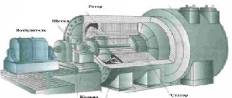
Power generation
electromechanical alternating current generators are the most common
. They convert the mechanical energy of rotor rotation into the energy of inductive alternating current, which arises due to the phenomenon of electromagnetic induction.
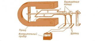
In Fig. Figure 1 illustrates the basic idea of an alternator: a conducting frame (called an armature
) rotates in a magnetic field.
Fig.1. Alternator circuit
The magnetic flux through the frame changes over time and generates an induced emf, which leads to the appearance of an induced current in the frame. Using special devices (rings and brushes), alternating current is transmitted from the frame to the external circuit.
If the frame rotates in a uniform magnetic field with a constant angular velocity, then the resulting alternating current will be sinusoidal. Let's show it.
Let's choose the direction of the normal vector to the plane of the frame. The vector thus rotates along with the frame. The direction of the frame bypass is considered positive if from the end of the vector this bypass is seen counterclockwise.
Recall that current is considered positive if it flows in a positive direction (and negative otherwise). An induced emf is considered positive if it creates a current in the positive direction (and negative otherwise).
Let us assume that at the initial moment of time the vectors and are codirectional. Over time, the frame will rotate at an angle. The magnetic flux through the frame at the moment of time is equal to:
(1)
where is the area of the frame. Differentiating by time, we find the induced emf:
(2)
If the resistance of the frame is equal to , then a current arises in it:
(3)
As we can see, the current actually changes according to a harmonic law, that is, it is sinusoidal.
In real alternating current generators, the frame contains not one turn, as in our circuit, but a large number of turns. This allows you to increase the induced emf in the frame by several times. Why?
It's not difficult to explain. In fact, the magnetic flux through each turn of the area is still determined by expression (1), so the induced emf in one turn according to formula (2) is equal to: . All these induced emfs arising in each turn are added to each other, and the total emf in the frame will be equal to:
Current strength in the frame:
where there is still frame resistance.
In addition, the frame is equipped with an iron (or steel) core. Iron multiplies the magnetic field inside itself, and therefore the presence of a core allows you to increase the magnetic flux through the frame by hundreds and even thousands of times. As follows from formulas (2) and (3), the induced emf and the current in the frame will increase by the same amount.