What is a contact network
Contact network is a set of linear current-carrying, insulating, supporting and supporting elements designed to supply electricity to the substation current collectors. The contact wire is made of chalk and its alloys (copper-cadmium and copper-magnesium) with a cross-section of 65–100 mm2. On auxiliary lines and lines in depots, copper wires with a steel core may be used. The wire must have good electrical conductivity, wear resistance and high strength to allow reliable tension.
The cross-section of contact wires is selected taking into account their cost according to the so-called economic current density from the condition of the optimal ratio between the consumption of non-ferrous metals and losses of electrical energy in the traction network. The hanging height of contact wires on lines under construction or reconstruction must be 6.0 m. A reduction in the hanging height is allowed inside production premises, under bridges and overpasses - up to 4.2 m, in tunnels - up to 3.9 m.
At high current loads of the contact network or when the voltage drop at the end of the section is greater than permissible, reinforcing wires made of copper, aluminum or twisted wire made of steel and aluminum wire are laid parallel to the contact wires to increase strength. At certain intervals these wires are connected to the contact wires.
Catenary suspension is a system for suspending contact wires to supporting structures. Depending on the method of hanging, fastening and maintaining tension, catenary pendants can be simple, chain and polygon. The distance between the points of attachment of the contact wire to the supporting structures is called the catenary span length. For fastening contact wires and supporting structures, various fittings with or without insulation are used.
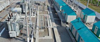
Traction substation - top view.
Polygon suspension is used when electric transport lines pass under artificial structures, on curved sections, city squares, etc. In this case, the entire suspension and contact wire are located in a horizontal plane. The contact wires of tram lines on straight sections of the track are arranged in a zigzag pattern with a distance from the center line of up to 400 mm for uniform wear of the current collector.
At the intersections of contact wires, air crossings and crosses are installed. They ensure the passage of PS current collectors without contact with the crossed contact wire along special guides. For this purpose, non-contact sections are organized at intersections, which the PS coasts through. Brackets, simple and chain flexible crossbars, beams and ceilings of overpasses, tunnels and other engineering structures are used as supporting devices in the contact networks of trams and trolleybuses. Flexible devices typically use galvanized steel seven-wire rope.
Supporting structures are intended for fastening supporting devices: special supports (reinforced concrete or steel), walls of brick and reinforced concrete buildings, structures of tunnels, bridges and overpasses.
The trolleybus contact network must ensure the movement of the trolleybus in the first and second lanes, and on the approaches to left turns - in the far left lane, provide for the possibility of timely changing lanes of the trolleybus, taking into account the specific road situation. The negative (zero) wire of the trolleybus contact network is located on the right side in the direction of travel.
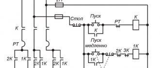
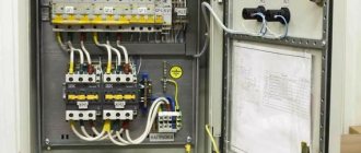
Traction substation control panel.
To change the direction of trolleybus movement, switches are installed on the contact network. Traditionally, switches of the trolleybus contact network are controlled similarly to trams, i.e. depending on the presence of traction when approaching the turnout. Modern turnouts are controlled using a radio signal from the driver's cabin. A transmitter (radio transmitting device) and a number of control buttons are installed in the cabin. On the contact network support next to the automatic switch there is a device that receives radio signals and supplies a control impulse to the switch drive, as well as a special traffic light that shows the direction of movement of the trolleybus at the current position of the switch feathers.
If the driver is satisfied with this direction, then he, without performing any actions, passes the arrow and follows the given route. If the driver needs to move the arrow in another direction, he presses a certain button on the control panel and thereby sends a radio signal that activates the arrow drive. Within 1.5-2.0 seconds, the direction of movement is switched, and the trolleybus follows a different path. After the car passes, the switch remains in its new position. Such arrows do not have de-energized elements, so the driver does not need to specifically reduce speed to pass them.
If several automatic switches are installed at one place on the route, then different buttons are used to control them. The radio transmitting device has four channels; to control each arrow at complex intersections, its own channel is determined. Similar arrows operate automatically without driver intervention.
Power plants
Traction substation buildings have different layouts and a different number of rooms and floors depending on the time of construction, but the general set of rooms, their area and interconnection are almost the same in all cases. The traction substations of direct and alternating currents include the following rooms: a switchboard room, where racks of control, protection, automation and telemechanics panels are located, auxiliary panels, panels or shields for heating, lighting and control of auxiliary equipment, as well as a table for duty personnel; battery with acid and ventilation for placing battery cans on special racks, a supply of acid and distilled water, as well as for ventilation equipment that provides sufficient air exchange in these rooms. Since battery and . acid rooms are explosive rooms; they are separated from the rest of the substation by a special vestibule. The installation of batteries on racks and their busbars were shown in Fig. 80; engine-generator room - an electrical machine room for charging and recharging units of a battery, and at alternating current substations of the first types - also for motor-generators SZCB. Heat exchangers were previously installed here. In recent years, due to changes in the operating mode, batteries and the transition to powering signaling devices with a current frequency of 25 Hz, as well as due to the introduction of silicon rectifiers, motor generators are not installed and most new substations do not have such a room. Instead, a room is provided for the installation of an emergency diesel generator for the power supply unit of the signaling and voltage supply system of the substation in the event of a loss of voltage at the inputs; auxiliary premises - bathroom, pantry, workshop, service room. The number of these premises varied depending on the building codes and regulations (SNiP) in force at certain periods of time. Substations in recent years have been built with a full set of such premises. In addition to the indicated premises, a machine room is constructed at DC traction substations, in which rectifiers with auxiliary equipment (except for PVE-5AU1 rectifiers), a 3.3 kV switchgear with a filter device, a 10 kV switchgear, and also, if necessary, devices for controlling absorbing recovery resistances and (in old types of substations) smoothing device reactors (in new types of substations they are placed in a special metal booth attached from the street to the substation building). In pre-war substation buildings, no special switchboard room was built, and the switchboard equipment was placed in the machine room. Before 1965, many DC substations were built on two floors, with rectifiers and 3.3 kV switchgear located on the second floor. In these cases, the 10 kV switchgear was taken out to a special building, which was constructed between the main building and the substation access road. The smoothing device and other auxiliary equipment were placed on the ground floor under the machine room. A special distribution device for powering signaling systems at substations where there is no 6-10 kV switchgear was also usually located in the machine room. The layout of the machine room of a DC substation with silicon rectifiers with natural cooling in accordance with the current standard design is shown in Fig. 81, and the layout of the AC substation according to the same project and its section through the switchboard room are shown in Fig. 82. Traction substation buildings are made of brick or rolled panels (at one time reinforced concrete blocks were also used). From Fig. 81 it can be seen that the 3.3 kV switchgear is single-row, leaning, with metal chambers. The outputs are bare busbars running from the cell to the walk-through slab in the wall of the building. All cells and passage plates are manufactured at the factories of the Ministry of Transport, and they are only installed at the substation itself during the installation process. A similar single-row leaning 10 kV switchgear, consisting of KVVO cells, is manufactured at the factories of the Ministry of Transport. In a silicon rectifier (CR) cell, all equipment - cabinets, manual and remote control panels, a high-speed reverse current circuit breaker - is installed during installation. In addition to consoles, shields and panels for the rectifier cell, factories produce special mesh fencing. In one-story substations without basements, cables are laid in cable ducts, which are covered with asbestos-cement slabs or corrugated iron. In two-story substations and one-story substations with a basement, the cables are placed on special structures suspended from the ceiling of the first floor or basement, respectively. Around the machine room, switchboard and other rooms in which the equipment is installed, a grounding loop is laid in the form of a steel strip with a cross-section of 40×5 mm attached to the wall. The metal housings of all high-voltage and other equipment are tightly connected to this strip. This grounding loop is removed from the substation and connected to the external grounding loop. At DC traction substations, to protect 3.3 kV switchgear equipment from currents, short circuits and to exclude the possibility of feeding the short circuit from the rectifiers of neighboring substations, earth relays are installed at the exit of the internal grounding loop from the building (in two places), which in the event of a short circuit turn off all 3.3 kV equipment.
Types of traction substations
Traction substation is primarily divided into two groups:
- Direct current.
- Alternating current.
The first of these options includes equipment designed for 6-220 kV. In this case, power is supplied via overhead and cable power lines. In the case when the voltage is below the threshold of 110 kV, a reduction is required; accordingly, the electricity first goes through the stage of reducing the value of the electrical parameters with the participation of a transformer.
In other situations, the energy is sent directly to the distribution board. device. A multi-type AC traction substation is by and large similar to equipment of this kind operating on direct current, with the only exception being the absence of a converting unit for rectifying the electrical characteristics.
Why is a traction substation needed?
Traction substation of different types is also found in other designs, the division is carried out according to the intended purpose of the transport:
- Equipment for the railway. Available in the following variants:
- Support – can act as a power source for other installations;
- Dead-end – receives electricity from a nearby substation;
- Intermediate - powered by two nearby installations.
- Traction substations for trams and trolleybuses. Equipment of this type also exists in several versions:
- With the need for the participation of service personnel;
- Fully automated;
- TP for trams and trolleybuses, which do not require personnel to operate the equipment and are remote-controlled equipment.
- Installations for the metro. The following types of such equipment are distinguished:
- Traction;
- Decreasing;
- Traction-lowering.
It will be interesting➡ What you need to know about current transformers
In the first case, a traction distribution substation is presented, powered by city power grids. The second of these options involves receiving high current from the traction unit, which is subsequently reduced to a level of 400-230 V, which is sufficient for power and lighting devices.
Transformer substation.
Specifications
Traction substations for trams, metro and trolleybuses and railway transport have a number of parameters according to which the required option is selected. By the way, if we compare them with equipment such as STP pole substations, which are powered by alternating current and are represented exclusively by a dead-end design, the range will be very wide, which makes the choice somewhat difficult.
To navigate a large number of designs, you need to clearly understand what loads will be placed on equipment of this type, according to which the equipment parameters are determined:
- the value of resistance and voltage on the buses where the rectified current is supplied;
- the traction substation of the metro, railway and other electric transport is characterized by internal resistance, as well as the resistance of the suction feeder and smoothing unit; using these values, you can obtain the resistance value of the entire installation by summing them up;
- Metro and Russian Railways traction substations differ in the number of transformers and switchgear used in the design. devices;
- the voltage of the entire installation is a calculated value and is determined from the formulas;
- short circuit power.
For comparison, the defining parameters for equipment such as pole-mounted transformer substations are: total power, as well as high and low voltage values.
High power traction substation.
Railway electric transport
Its contact network is extensive. And often in places where there are no other sources of electric current. Therefore, not only direct but also alternating current can flow through it, which is transmitted over long distances with less losses.
Nominal contact line voltage
The substation is supplied with a voltage of 220 or 110 kV alternating current, and if the contact network is outdated, then 35 kV. For DC power systems it is converted to 3.3 kV, and for alternating current to 27.5 kV.
To meet the needs of the railway infrastructure (semaphores, switches, office premises), the traction substation equipment includes a transformer winding, from which the voltage of 10 kilovolts is removed. It is converted to three-phase linear 380 volts (a system with a solidly grounded neutral), allowing you to switch to household 220 volts 50 Hz.
Organizational structure of the contact network
In railway transport there are the following types of traction substations:
- Supporting. At least four autonomous power lines are connected to them. They are the main sources of power for the contact network. If direct current is used, then the distance between them is no more than 15 km. With variable it increases to fifty.
- Transit, powered by two independent power lines and connected to the gap between the supporting substations. They ensure the transmission of electricity over long distances, as well as the continuity of power supply to the contact network in the event of an accident at one of the sites.
- Sealing (dead-end). They are used to ensure the movement of electric trains on separate branches. The tap substations are powered by two independent power lines.
- Docking. They are used where there is a change in the type of contact network. They provide galvanic isolation between alternating and direct current.
Catenary design
Three-phase asynchronous motors are not used in electric vehicles of any type due to the excessive increase in the cost of the contact network, the complexity of current collectors and the impossibility of their operation at high speeds. There is always one overhead contact wire and it is phase. The role of the zero is played by the rail, therefore, within a few tens of meters from the railway track, so-called stray currents are recorded.
On long hauls, in order to reduce losses, the AC traction substation produces 50 kV, this voltage is divided in half (25x2 circuit) between the supply and contact wires using an autotransformer, the central point of which is closed to the rail. The AC contact network can also carry direct current. For this purpose, a connecting traction substation is used, which switches the type of voltage in a certain area.
AC electric locomotives - VL80, VL85 - are equipped with rectifiers and motors capable of operating on pulsating current. They are designed for a nominal voltage of 25 kilovolts - 2.5 kilovolts are lost due to the high circuit resistance between the contact wire and the rail. Models VL10 and VL11 operate on direct current, and VL82M has both types of drive.
AC traction substation
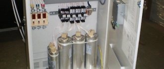
The AC traction substation serves only to reduce the voltage (transformation) of the alternating current received from the power systems. A single-phase current of this voltage powers the contact network. AC traction substations of the 2×25 kV system with a primary voltage of 110 (220) kV have a structural diagram, the peculiarity of which is the use of special single-phase transformers and their connection to the traction network. At AC traction substations, capacitor banks are used. At AC traction substations, in many cases, equipment is installed, the need for which is determined by the type of current and its effect on communication lines and low-voltage electrical networks running parallel to the railway.
Scheme of an AC traction substation.
For this purpose, at traction substations, special installations are used to increase the power factor of the traction load, signaling devices for powering lines with high-frequency current, and compensating devices. At AC traction substations, high-voltage traction voltage cables must be unarmoured and in a non-metallic sheath. In addition, the switchgear must include measures to prevent heating of metal structures by single-phase alternating current.
At 2×25 kV AC traction substations, two working and one backup transformers are installed. Powering traction loads from single-phase transformers assembled according to an open delta circuit forces the installation of additional two or three winding transformers to power regional non-traction consumers.
At combined AC traction substations (for electricity consumers of categories I and II), as a rule, two traction and two separate transformers are installed to power the power load. At AC traction substations built between 1954 and 1961. In auto-blocking power supply circuits at a frequency of 75 Hz, in addition to the listed transformers, autotransformers are installed. In an autotransformer, the low voltage winding is part of the high voltage winding.
The district is powered from alternating current traction substations with a higher voltage of PO kV can be supplied either from three-winding traction transformers or from individual transformers installed at traction substations. If a single supply voltage is required to power the area, the most appropriate power supply circuit is from the third winding of traction transformers. In the presence of an existing district load on two voltages, it may be a more economical option to supply traction and district consumers from separate transformers.
Additional material: How to make a 4G antenna.
The efficiency of a separate power supply scheme increases in cases where it is possible to limit the installation of one transformer to power traction, and also when a traction substation is built near an existing regional substation. The power of transformers STp of AC traction substations depends on the magnitude of the traction load on power arms 1a and /fr and on the power of the railway non-traction S. Due to the high power of AC traction substations, voltages below PO kV are not used to power them. Therefore, when placing such a substation near a district one, it is recommended to place them on the same site.
How does a traction substation work?
5.2 .
Classification and block diagrams of traction substations of electric railways
To classify a traction substation means to verbally describe its most characteristic circuit and design features. It is customary to classify traction substations according to the following criteria:
— voltage and type of current (direct or alternating) at which energy from the traction substation is supplied to electric trains;
— primary voltage, i.e. the voltage in the power line to which the traction substation is connected from the external power supply system;
— diagram of connecting the traction substation to the external power supply system;
— method of servicing the traction substation;
- the method of controlling the equipment of the traction substation, as well as other characteristics not mentioned above, if indicating them is appropriate.
According to the first criterion, traction substations are distinguished: direct current with a voltage of 3.3 kV; alternating current voltage 25 kV;
alternating current with a voltage of 2×25 kV and direct-alternating current (butt), serving sections of two traction systems at the point of their joining.
DC substations use primary voltage of classes 6-10-35-110 and 220 kV, alternating current - 110 and 220 kV.
To the external system
power supply, traction substations can be connected according to various schemes. Substations connected according to the diagrams shown in Fig. 5.4, a, b
and c are called intermediate, according to the diagram in Fig. 5.4,g - support ones. In turn, intermediate substations are divided into intermediate transit (Fig. 5.4, a, b) and intermediate on branches (Fig. 5.4, c). The peculiarities of connecting a substation are certainly reflected in the diagram of the substation itself, which will be discussed below.
According to the method of maintenance, traction substations are divided into substations without personnel on duty, with duty at home and with permanent personnel on duty. According to the control system, they distinguish: remote-controlled substations, i.e. those whose equipment can be turned on and off by a dispatcher using a telecontrol system and being at a considerable distance from the substation (100 -250 km); without remote control, i.e. those that require you to be directly at the traction substation to control them.
Let's try to further classify traction substations using the example of a description of their structural diagrams. Structural diagrams are diagrams that show the principle of electrical installations at the level of large functional units - structures. One of the most important functional units of any substation, including traction, is the switchgear. The purpose of the switchgear is to receive electrical energy from any source through special lines (inputs) and distribute it to consumers using outgoing supply lines.
Another, no less important functional unit of the substation is the transformer. There are step-down transformers, the purpose of which is to reduce the voltage, and converter transformers, the purpose of which is to lower the voltage and, if necessary, simultaneously increase the number of phases on the secondary winding. Converter transformers power rectifiers and inverters. The latter can also be considered as separate functional units. Rectifiers convert (rectify) alternating current, at which energy is supplied to the rectifier, into direct current, at which it is then used by electric trains. Inverters perform reverse conversion (inversion) of the direct current energy generated by the eps. during braking at stations or on steep descents, into alternating current energy, on which it is returned through a converter transformer to the external power supply system.
Other functional units specific to certain types of traction substations will be clear from a review of the structural diagrams.
Block diagram of a 3.3 kV DC intermediate traction substation with a primary voltage of 110 (220) kV and a 35 kV switchgear for powering the area.
Main functional units of the traction substation (Fig. 5.5): / - RU 110(220) kV; // - a step-down transformer; /// — RU 35 kV; IV—RU 10 kV; V
— converter transformer; VI - rectifier; VII - RU 3.3 kV; VIII - smoothing device.
Rice. 5.5. Block diagram of a 3.3 kV DC intermediate traction substation
Inputs, supply lines and other connections are marked with Arabic numerals. Through inputs 1, three-phase voltage 110 (220) kV, transmitted over three wires, is supplied to switchgear 110 (220) kV I, from where through connections 2 - to step-down transformers II. These transformers are three-winding, so with the HV and LV windings they reduce the primary voltage to 10 kV, and with the HV and SN windings - to 35 kV. Through inputs 5, a voltage of 10 kV is supplied to the 10 kV IV switchgear, and through inputs 3, a 35 kV voltage is supplied to the 35 kV III switchgear. Through supply lines 4, a voltage of 35 kV is supplied to the 35 kV switchgear of the district's transformer substations (not shown in the diagram), along lines 6, a voltage of 10 kV is supplied from the 10 kV switchgear IV for
supply of non-traction railway consumers. The lines are usually placed on the field side on the contact network supports (see Fig. 5.1).
Through connections 7 from the same 10 kV switchgear, converter transformers V receive three-phase voltage. They reduce the voltage to 1.52 kV. This voltage is fed to VI rectifiers, which convert it to 3.3 kV DC voltage. Therefore, from the rectifiers in RU 3.3 kV VII there are already only two wires (two buses): 9 and 10. The potential of bus 9 is higher (it is indicated by the + sign), bus 10 is lower (it is indicated by the sign -), and the potential difference between the buses (voltage) is 3.3 kV.
Through the 3.3 kV switchgear and the supply line (feeder) of the contact network 11, the potential of the bus 9 (+) is supplied to the section of the contact network 17, and through the smoothing device VIII and the rail feeder 21, the potential of the bus 10 (-) is supplied to the rails 20.
A few words about the smoothing device VIII. It is designed to sharply (50-100 times) reduce current ripples in the traction network, which would arise under the influence of a pulsating, not ideally smoothed voltage at the output of rectifier VI and cause interference in a wired communication line running parallel to the railway route.
To other sections of the contact network, bus potential 9 (+) is supplied through contact network feeders 12, 13, 14. Adjacent sections along the same path are separated by an air gap 18. Note that the traction substation circuit itself ends where in Fig. 5.5 there is a dashed line (below the 3.3 kV switchgear).
Thus, between any section of the contact network and the rails, the potential difference (voltage), depending on the magnitude of the traction load of the substation, is 2.7 - 3.3 kV. This allows the driver of the e.p.s. 19, having connected the motors, assemble a closed current circuit. At the same time, the engines will begin to consume electrical energy, converting it into mechanical energy for the train to move.
Let us recall that electrical energy is generated by generators of power stations of the external power supply system, from where it is transmitted first through power lines and regional substations of the external power supply system, and then through the traction substation and traction network to the electric power supply system. 19. In accordance with general laws, transmission
electrical energy is accompanied by losses in all parts of the transmission path: from source to consumer. This means that if a consumer (in our case e.p.s. 19) received AE kWh of energy for some time, then the power plants of the system must generate during the same time A = A e P p kWh of active energy, where p — efficiency of the energy transmission path.
Another thing is also significant: simultaneously with the active energy A, kWh, the stations must, during the same time, also generate reactive energy AR, kvar-h, which does not produce work and only loads the system by the flow of current. This energy is determined by the inductance of the transmission path and the properties
consumers of active energy. Without the consumption of reactive energy, not a single converting unit can operate, by which we mean a rectifier and a converter transformer, taken as a single whole.
To fully understand the processes of energy conversion in the circuit of the traction substation under consideration, it is necessary to pay attention to the following: between the true sources of electrical energy - electric stations and e.p.s. 19 exists somewhat galvanically, i.e. electrically separated but magnetically coupled current circuits, each of which has its own formal energy source and formal energy consumer. At the same time, all formal sources and consumers of energy have signs of being true. In the scheme under consideration there are three such circuits.
The first is a 3.3 kV DC circuit. Formal energy source: VI rectifiers together with LV windings of converter transformers. The formal consumer, who is also the true consumer, is e.p.s. 19. The current circuit (in accordance with the accepted positive direction of the electric locomotive 1E current, indicated by the arrow) is closed in series: nn V - 8
- V - 9 - VII - 11 - 17 - 19 - 20 - 21 - VIII - 1 - 15 - VII - VI - nn V. By measurements it can be established that the largest voltage drop in this circuit occurs at the eps. This means that the e.p.s. consumes the main share of energy consumed in this circuit, where it is mainly converted into electrical energy for the movement of the train and is only partially lost in the form of heat.
The second is a three-phase alternating current circuit of 10 kV. Formal energy source: LV windings of transformers II. Formal
consumer: HV windings of converter transformers V. Currents flow through three wires (phases) of the circuit in question. The largest share of the active component of the voltage drop falls on the windings of high-voltage transformers V, which gives the right to consider them an energy consumer.
A natural feature of the two considered magnetically coupled circuits is that the element separating them - converter transformers V - is both a source of energy in the first circuit and a consumer in the second. This has a physical explanation: only by consuming most of the energy in the second circuit can its economical transfer to the eps be ensured. 19 in the first.
The third is an alternating current circuit of 110 (220) kV (partially shown in Fig. 5.5). Formal consumer: VN step-down windings
transformers II. The formal source is not shown in the diagram and is located in the external power supply system. Most likely, these are the secondary windings of step-down transformers at regional substations or the windings of step-up transformers at a power station. This means that the third circuit under consideration is not the last one before
The true source of electrical energy - generators of power plants - must still have at least one magnetically coupled circuit. The largest share of the active component of the voltage drop in the circuit falls on the windings of high-voltage step-down transformers II.
DC traction substation (Fig. 5.6). The substation has the same block diagram as in Fig. 5.5, the order of structure designation is preserved. In the upper left part of the figure you can see the 110 kV / switchgear, which houses equipment that is still unfamiliar to us. Among it, we highlight switch 41, disconnectors 39 and 43, separator 46 and arrester 42. All these elements ensure the normal functioning of a switchgear of this type. Three connection wires 2, located between insulators 116 mounted on the portals 115 of the switchgear, and insulators 126 on the portals 127, supply voltage to the step-down transformers //. From each step-down transformer comes input 5 to switchgear 10 kV IV, which is located inside the building of substation 132, at its left wall, and can be seen in Fig. 5.6 thanks to the conventionally removed roof of the traction substation building.
The main switching equipment in 10 and 3.3 kV switchgear cells (IV and VII) - switches and disconnectors - will be discussed in more detail in section 5.3. this textbook. A smoothing device is located in the lower right corner of the traction substation building and in the outside extension VIII. From the substation building, through feeders 11-14 and rail feeder 21, a rectified DC voltage of 3.3 kV is supplied to the traction network. The 35 kV switchgear of the traction substation /// is mounted on the left side of its territory and is made of standard blocks 109, united by a system of busbars 110. The busbars are fixed between crossbars 113, mounted on supports 11, and isolated from the latter by garlands of insulators 112. The 35 kV switchgear receives power supply to inputs 3 through input block 125 and line 119 from the same step-down transformers II. The 35 kV switchgear blocks are open, so at the beginning and end of the block of outgoing line 109, which supplies district consumers, disconnectors 22 and switches 24 are clearly visible.
A comparative large-scale comparison of the elements of the territory of a traction substation can be carried out by taking as a reference the length of the oil car 121 (20 m) introduced into the territory of the traction substation, or the height of a person (1.8 m).
Rice. 5.6. DC traction substation
In addition to those considered, the figure also shows other structural elements of the traction substation: the 110 kV switchgear frame, consisting of supports 103 and crossbars 104, 108, free-standing supports with lightning rods (divertors) 133, etc.
Block diagram of a 25 kV AC support traction substation with a primary voltage of 110 (220) kV and a 10 kV switchgear for powering the area (Fig. 5.7). Main functional units of the traction substation: I - RU 1 10(220) kV; II - step-down transformers; III - RU 10 kV; IV—RU 25 kV.
Through inputs 1, three-phase voltage 110(220) kV is supplied to the 110(220) kV switchgear. This switchgear has a more complex circuit and design than the switchgear of the same voltage in Fig. 5.6, since it is designed to receive and distribute energy that can flow through four inputs at once. Through connections 2, the three-phase voltage from the switchgear 110 (220) kV is supplied to three-winding step-down transformers II, which with the HV and SN windings reduce the primary voltage to 25 kV, and with the HV and LV windings - to 10 kV. A voltage of 25 kV is used to power the electric power. p.s., and 10 kV - district. The latter from transformers II is supplied via inputs 3 to the 10 kV switchgear of traction substation III, from where via supply lines 4 to the transformer substations of the region's consumers (not shown in the diagram).
The supply of 25 kV voltage to the sections of the traction network to the left and right of the substation is provided through RU25 kV IV via contact network feeders 8 (phase a), 9 (phase b) and rail feeder 6 (phase c). The section of the traction network to the left of the substation (between the contact network 15 and rails 22) is supplied with a single-phase voltage Ua-c = 25 kV (effective value), and to the section to the right (between the contact network 19 and rails 22) -
single-phase voltage Ua-b also with an effective value of 25 kV. Due to the difference in voltage phases between the sections of the contact network on the left 15 and on the right 19, they are separated by a neutral insert 17. From the 25 kV switchgear through two-phase feeders 7 and 10, voltage is also supplied to the DPR lines, respectively on the left 13 and on the right 14, used to power non-traction consumers 20 and 21.
Energy consumption eps 23 begins after connecting its circuits between the contact network 19 and the rails 22. In this case, the energy from the true source of electrical energy - power stations (not shown in the diagram) - to the true consumer - e.p.s. 23 -transmitted sequentially through several magnetically coupled but galvanically separated current circuits, each of which has its own formal source and formal energy consumer. There are two such circuits between inputs I and train 23.
The first is a 25 kV alternating traction current circuit. The formal source of energy is the windings of the transformer. The formal consumer, who is also the true consumer, is e.p.s. 23. The traction current is closed along the circuit SN II - 5 - IV -
9 - 19 - 23 - 22 - 6 - IV - 5 - dn II. The maximum share of the active component of the voltage drop falls on the e.p.s. 23.
The second is an alternating current circuit of 110 (220) kV. The formal consumer is the external windings of transformer II. The formal source is not shown in the figure, but most likely these are the windings of step-down transformers at regional substations or the windings of step-up transformers at a power station. This means that the second circuit under consideration is not the last and before the true source - the generators of power plants - there must still be at least one circuit.
The maximum share of the active component of the voltage drop in the second circuit falls on a fictitious consumer - the windings of the external transformer //. It is easy to see that in this case, the formal source of energy in the first circuit - the transformer // - is a consumer in the second circuit. An explanation for this is given above when considering the circuit of a DC substation. It should be noted that the diagram of the traction substation ends where in Fig. 5.7 there is a dashed line.
Figure 5.7 shows the power supply circuit through feeders 9, 10 and rail feeder 13 of the traction network of the first railway track. Similarly, through feeders 11, 12 and rail feeder 13, the traction network of the second track is powered (not shown in the diagram).
Block diagram of an intermediate traction substation alternating current 2×25 kV with a primary voltage of 110 (220) kV.
A shutdown due to a malfunction of any of the transformers II or III disrupts the voltage system of the 2x25 kV switchgear (see Fig. 5.9). In this case, trains in one of the zones (to the left or right of the substation) and all non-traction consumers (both to the left and to the right) are deprived of power. To eliminate such an unpleasant possibility, the substation has a third, backup transformer IV, which, through supply line 7, can receive from the 110 (220) kV switchgear I either voltage UCA as transformer II, or voltage UAB as transformer III and supply it to switchgear 2×25 kV voltages in phase with the voltages supplied by transformers II and III. To accomplish this, RU 110(220) kV I and RU 2×25 kV V have appropriate switching systems. Since the voltage between the sections of the traction and supply networks on the left 21 and 29 and on the right 25 and 31 of the traction substation is different (see Fig. 5.9), they are separated from each other by air gaps 22 and 24, neutral insert 23 and gap 30. Power supply to regional consumers carried out from RU VII via supply lines 9. Voltage in RU VII is supplied through inputs 10 from a special transformer VI connected to RU 25 kV V by wires II. It should be noted that the diagram of the traction substation ends where in Fig. 5.8 there is a dashed line. As in the block diagrams of the traction substation discussed above (see Fig. 5.5 and 5.7), in the diagram in Fig. 5.8 between the true consumer of electrical energy - e.p.s. 27 - and the true source - generators of power plants (not shown in the diagram) - there are several galvanically separated, but magnetically coupled current circuits, each of which has its own formal source and consumer of energy.
content .. 21 22 29 ..
Classification depending on purpose
In accordance with the operating conditions, the traction substation can be classified into one of the following groups. For railway transport, support, dead-end, and intermediate varieties are used. In the first case, the installation can be used to power other objects. Dead-end devices are provided with electric current from neighboring substations, and intermediate ones - from two neighboring installations.
Special types are used for trolleybuses and trams. The first group of devices requires the participation of maintenance personnel. The second category is fully automated. The third category includes remote-controlled equipment. The management of such stations does not require the participation of personnel. For the subway, step-down, traction and traction-step-down devices are used. In the first option, the system is powered by city power supply equipment. The second type reduces the voltage to 400-220 V. Its energy is used to power lighting and power devices.
General view of the electrical substation.
Design Guidelines
Transformer power alone is not enough to properly design an installation. A whole list of parameters that affect the operation of the equipment should be taken into account. The amount of voltage and resistance on the buses into which current is supplied. The substation itself has a certain level of resistance, as well as the resistance of the feeder, smoothing unit. When choosing an installation, the total amount of this parameter must be taken into account.
It will be interesting➡ How does a power transformer work and where is it used?
The design can use a different number of transformers and distributors. When choosing, take into account the operating conditions of the equipment. Using generally accepted formulas, it is necessary to calculate the total value of the required installation voltage. The short circuit power is also taken into account. In most cases, the total power of the equipment, as well as low and high voltage indicators, are taken into account.
Substation for the residential sector.
Structure
The description of the typical circuits of the presented devices is quite complex. However, common features can be identified. The connection in the system is made in accordance with the characteristics of the transport for which the unit is used. The distributor consists of three blocks. The first contains a device that receives high voltage, the second compartment contains a transformer, and the third contains an output for electricity with specified characteristics. There is only one switch. There is a disconnector at the input.
The connection of the primary windings is carried out according to the star circuit. The zero phase must be grounded. The secondary windings are connected in the form of a triangle. One of the phases is grounded and connected to the rail. The metro has a special contactor for this purpose. This rail is intended solely for relieving the stress of an electric locomotive. The other phases feed into two overhead cables. They are sometimes used to supply electricity to other consumers, but mainly traction substations provide power to trolleybuses via overhead wires.
For a tram, this process involves one overhead wire and one ground rail. In most countries of the world, the voltage for such a network is 550 V.
Substation power supply
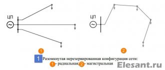
The traction substation must provide an uninterrupted supply of electricity for vehicle movement. Therefore, many of these units are powered from two autonomous networks at once. In this case, a single-line diagram of a traction substation can be used or using two backup lines to another power source. It is also possible to supply power via jumpers between individual substations.
Substation power supply
If the option of two separate lines is used, each of them must be designed for the maximum load of the unit. Redundant communications must be able to withstand the total load of the connected stations. Previously, a radial circuit was used to power subway networks. It is complex and expensive. It requires too much cable. They didn't seem like it from her. Today, only the above schemes are used. Lines and jumpers allow you to combine equipment into separate groups. If one device inside it fails, other units take over its functions.
Also, when carrying out routine maintenance of units, all operations will be simpler, without causing the system to stop. In this case, it is possible to de-energize only one unit. Other devices will ensure the operation of the line. This approach to routine repairs greatly simplifies the work of personnel, making maintenance less expensive.
Use of traction substations
The purpose of the traction substation is as follows: to convert and distribute electric current for the purpose of servicing electric vehicles. Substations are divided according to the type of electric current supplied to the contact network - direct and alternating - depending on what type of electric transport is used: electric locomotives of surface railways, subways, trams or trolleybuses. A traction substation can provide electricity to other consumers, not just the railway.
A traction substation can be stationary or mobile. Mobile ones are used quite rarely. The distance between traction substations with direct current in the contact network, they are erected in increments of ten to fifteen kilometers. The distance varies depending on the required power, which depends on the tension in the movement of trains and the terrain.
The traction substation is powered from power lines laid over the air on supports, or through a cable network. The external voltage is reduced by the transformer and transferred to the rectifier, from which electric current is supplied to the contact network. Currently, energy recovery is widely used on electric locomotives and other types of electric transport. When braking, electric locomotives, trolleybuses, trams - consumers of electric current, turn into its source. Electric motors become generators and transmit electric current to the contact network, thereby absorbing the kinetic energy of movement and providing braking for electric vehicles.
Substation contact network.
An inverter is used to flow the current back into the power grid. They automatically turn off the rectifiers as soon as the vehicle braking in recuperation mode begins to produce current. On the railway, the nominal voltage level is considered to be 3300 Volts, in subways 825 Volts, in the contact network of trolleybuses and trams 600 Volts.
AC substations differ from similar DC substations in the absence of a rectifier; a step-down transformer supplies current directly to the contact network.
The distance between traction substations that use alternating current is higher than for stations using direct current - up to fifty kilometers. And the voltage that electric vehicles remove is 27.5 kilovolts. Power supply from an external network for them ranges from 110 to 220 kilovolts. The connection diagram of the primary windings of the step-down transformer of such stations is a “star” with a grounded zero phase. The secondary windings are connected in a delta pattern.
One of the phases is grounded and connected to a rail, which serves as one of the contact wires for the electric locomotive. In the subway, this is a separate contact rail, which serves solely to relieve voltage from the subway electric locomotive. The other two phases supply current to two overhead wires on different paths and are also used to supply other electrical consumers.
There are quite a lot of the latter near railways. This includes automation that controls the movement of trains, signaling devices, communications, lighting of platforms and station buildings, their heating and much more. Traditionally, in many areas, the railway power supply system is the only way to supply voltage to populated areas. Therefore, the traction substation is not only used for electric transport, but also supplies populated areas and other consumers with electricity, meeting their needs.
Power lines.
The traction substation and their groups provide service to ground, mainly urban, electric transport - trolleybuses and trams. They convert current from external networks into direct current and transmit it to contact wires or rails. For trolleybuses there are two contact overhead wires, for trams there is one overhead wire and a rail. The voltage used in most countries is 550 Volts.
It will be interesting➡ What is a pulse transformer and how to calculate it
A traction substation can be remote-controlled, fully automated, or have service personnel. Most often, personnel are present at small stations in small cities. Where the creation of automatic control systems is not economically feasible.
Or, on the contrary, at large traction substations, whose value is too great to have the risk of shutting them down. Often, personnel are present only at one of the traction substations, from where other stations included in the overall system are remotely controlled. The presence of personnel does not exclude automatic control. In this case, the person is assigned the role of an observer-controller who can intervene in the operation of the substation in emergency cases requiring decision-making and in emergency situations.
How does a traction substation work?
Fully automated stations are used where the intensity of train traffic is low, and the stop should not entail far-reaching consequences in terms of safety. The most reliable and economical control system is remote. A traction substation can be single-unit or multi-unit. Single-unit ones are used where a centralized supply of electricity is not required, on branches. They are quite rare because they do not provide a reliable supply of electricity. If the unit fails, the entire network served by the substation is de-energized. Therefore, two-unit substations are most often used. There are both three-unit and four-unit ones.
The presence of several units significantly increases operational reliability. When one unit fails, the second one turns on, which ensures uninterrupted operation. Also, the presence of more than one unit gives flexibility to the work at times of maximum load. Combining several substations into a single group controlled from one center makes it possible to make them interchangeable, reduces the cost of construction and operating costs.
Interesting read: How to solder aluminum with your own hands.
Since the main condition for the operation of a traction substation is uninterrupted operation, they are all powered simultaneously from two different external networks. Power supply can be carried out via separate lines, or from one using the main and backup lines to another substation; the option of connecting with jumper cables between substations is possible.
When using two separate lines, both must be designed for the maximum load of the substation. The backup connection must simultaneously withstand the load of the connected stations; the connection with a jumper cable must withstand one. Scheme number two is most often used in the metro, as it is quite reliable, economical and easy to manage.
Previously, when the construction of the metro in the country was just beginning, a radial line design was used to power substations from city networks. However, such a scheme is quite complex; it involves many cables and cells. Therefore, it was soon abandoned. Now powering is done using lines and jumpers. This ensures the consolidation of substations into separate groups. If one of the step-down transformers in the group fails, the others redistribute its load.
How does an electric locomotive and traction rolling stock work?
Traction substationsTraction substations of direct and alternating current roads differ significantly in design. However, both of them must meet the following requirements: ensure reliable power supply to locomotives, be as simple as possible, and be safe to maintain. It is also desirable that the costs of their installation and operation be low.
Let's get acquainted with the design of a typical DC traction substation (Fig. 132). It has two power transformers 77 and T2 (there may be more of them). Each of the transformers is connected to its own rectifier B, assembled using a three-phase bridge circuit. The cathodes of the rectifiers are connected by high-speed switches BV and disconnectors R to the bus <-(-> of the DC switchgear switchgear. The anodes of the rectifiers are connected by disconnectors to the bus <->.
The <+> bus, or, as it is also called, the main bus, is connected by feeders to the contact network. The feeder for protecting substations from short circuits in the contact network includes a high-speed circuit breaker BVf and two disconnectors Rf. By disconnecting these disconnectors, the high-speed switch can be inspected or inspected in a safe environment. Short circuit protection must act selectively
and do not disconnect the contact network in difficult operating conditions, for example, when several units of electric rolling stock are launched at the same time, sharp fluctuations in loads associated with the regrouping of traction motors.
There are usually several feeders (one is shown in Fig. 132). Their number depends on the number of electrified tracks on the stretch, the track development of stations, and the availability of depots. The <-> bus (also called the return bus) is connected to the rails by a suction air or cable line.
Let us explain the features of alternating current rectification at traction substations. It was noted above that the rectified current at substations is practically constant, in contrast to the pulsating alternating current in electric locomotives. This is explained by the fact that three-phase current is rectified at traction substations, in contrast to single-phase current, which is supplied to AC electric locomotives.
With single-phase current, a two-period rectification circuit is used to reduce ripple (see Fig. 62, b); According to the same scheme, all three phases of the secondary winding of the transformer, connected by a star, are switched on. Six groups of valves operating alternately are connected to the windings. This provides six-phase rectification. In addition, to smooth out the ripples of the rectified current, a smoothing reactor CP is included in the <-> bus. l Scheme Fig. 132 simplified; for example, it does not show a spare tire and a spare fuel pump, with the help of which, without interrupting the power supply, you can replace any feeder fuel pump; A number of other devices and apparatuses are also not shown.
To further reduce fluctuations in the rectified voltage, you can use parallel operation of two converter units, each of which has six-pulse rectification circuits. The rectified voltage ripples of each installation follow with a shift of 360°:6= = 60°. If you artificially make an additional shift of 30° when two rectifiers operate in parallel, then the output lines of the substation will have a rectified voltage with a 12-phase ripple. The deviation of these oscillations from the average value of the rectified voltage is less than with a six-pulse circuit.
Rice. 132. Schematic diagram of a DC traction substation
In order to be able to carry out recovery on electric rolling stock, regardless of the presence of a consumer on the line, inverters or absorbing devices are installed at substations. The principle of inversion (converting direct current into alternating current) was considered in relation to installations on electric rolling stock. Unlike the one considered, the inverter located at the substation is multiphase: it converts direct voltage into three-phase.
In the USSR, rectifier-inverter units are mainly used, the power circuit of which is designed to operate in two modes: rectification and inversion. In the presence of such an installation, recovery energy is transferred from the traction substation to the primary (external) power supply system.
Absorbing devices consist of resistors. Absorbing resistors, in which the recuperation energy is uselessly dissipated, are advisable to use only when the amount of recuperation energy supplied to the substations is insignificant, and this energy is mainly consumed by electric locomotives in traction mode. This is possible on multi-track electrified sections with heavy traffic, where there are always electric locomotives in the power zones that consume energy.
However, at some points in time, electric locomotives—consumers of recovery energy—may be briefly absent in such areas. In the absence of receivers of this energy, regenerative braking failures of trains moving at high speed along a slope are possible. This is unacceptable both from the point of view of traffic safety and due to the occurrence in such cases of excessively high voltage, which is dangerous for traction motors.
Therefore, absorbing resistors are installed at traction substations, serving as a backup receiver of recovery energy at specified times. They should be switched on without inertia as soon as the voltage in the contact network exceeds the voltage at the output of the rectifier installed at the substation.
At substations of AC roads, power transformers of various types are used with different circuits for connecting their windings, depending on the size of the loads and the power supply conditions of the traction substation. In the case of powering a traction substation from two power transmission lines (PTLs), the primary windings of transformers 77 and T2 (Fig. 133) are connected to different power lines.
If necessary, these windings can be connected to the same power line using a jumper (the jumper is not shown in Fig. 133). Two phases of the secondary windings of transformers, for example L and C, are connected to the buses of the traction substation.
The buses are connected by high-voltage explosive switches and feeders to the contact suspensions of tracks I and II of the double-track section. The third phase (in our example B) is connected to the rails. A more or less uniform load of the phases is ensured by connecting catenary I to phases L and C.
Contact pendant II of another path is also connected. To prevent a short circuit between phases L and C, the contact pendants are electrically separated by neutral inserts.
Rice. 133. Schematic diagram of an AC traction substation
Traction substations also have transformers for powering their own needs (for example, lighting, heating, etc.), voltage transformers for powering relay protection, meters, etc. These connections are shown in Fig. 132 and 133 are not shown. Railway signaling, communication, and automatic blocking devices receive power from traction substations.
Electrification of railways simultaneously contributes to the development of a centralized supply of electricity to industrial enterprises and rural areas adjacent to electrified lines.
To supply power to non-traction consumers, transformers of AC road traction substations have a third three-phase winding connected to buses L', B', C'. At the traction substations of DC roads, separate TZ transformers are installed (see Fig. 132), which supply regional consumers.
Many traction substations have essentially turned into regional substations, the loads of which are largely determined by non-traction consumers. The use of electricity in labor significantly increases productivity and improves the living and recreational conditions of the population. The electrification of railways plays an important role in solving these problems. In addition, in areas through which electrified railways pass, it is possible to close low-power transport, industrial and rural power plants, which has a significant economic effect.
Read about the structure and design of electric locomotives and rolling stock...
Diesel locomotives for industrial use
Recommendations for selection
The main criterion for the effectiveness of using a particular type of installation is the compliance of the parameters with the operating conditions, in particular, the level of the supplied load. If a traction or pole transformer substation is selected, its typical design implies the need to perform the following actions:
- Selection of connection diagram and connection of main components;
- Determination of the most suitable option for current-carrying devices and components;
- Based on the calculated values of electrical parameters, the main components of such equipment (switchgears, transformers, switches, disconnectors, protection elements, charging batteries) are selected.
Similar actions are performed in the case when a mast transformer substation is selected; a typical project will also largely consist of a calculation part.
What is a traction substation and how is it designed?
Installation nuances and regulatory documentation
The main feature of the principle of installation of equipment used to power railway electric transport is that all work is carried out with the direct participation of electrical installation trains. The list of key tasks includes the installation of the traction substation itself, and at the same time the sectioning posts, telemechanical equipment and contact network. Equipment such as pole-mounted transformer substations are connected in a slightly different way, given that all the main components are mounted on a support.
STN TsE 12-00 “Standards for the production and acceptance of construction and installation work during the electrification of railways” define a number of requirements for the installation of such equipment. For comparison, a mast-mounted transformer substation involves preparing a pit for installing a support, checking the accuracy of the installation using plumb lines, installing the main components on the supporting structure, and connecting all elements.
Thus, traction units are distinguished by a variety of designs, which, on the one hand, somewhat complicates the choice of such equipment, and on the other, allows you to choose the most suitable option. But pole-mounted transformer substations are equipment for a narrower purpose and represent a dead-end design option for a certain range of power values and voltages. When choosing any of these types of equipment, the level of load withstand, the connection diagram, as well as the compliance of the main parameters with the operating conditions are taken into account.
Installation of a traction substation.