Couplings: description classification
Couplings: description, classification
A coupling is a device for connecting shafts. The main purpose of couplings is to transmit torque between shafts, without changing its value and direction. In addition to transmitting torque, some couplings perform additional functions.
In order to buy a coupling, you need to know the main fundamental differences between them. According to the manufacturing and assembly technology, long shafts have to be made composite, and the composite shaft must work as a whole. Its parts are connected with rigid, blind, non-disengaging couplings.
To connect shafts with inaccurately aligned axes, compensating couplings are used that compensate for small radial, axial or other displacements. Some machine drives transmit variable torques, including impacts. To reduce dynamic loads and vibrations, elastic couplings are used. To start and stop individual machine components, controlled couplings are used. Overloads and improper operation may cause parts to break, so safety couplings are used to prevent this from happening. If movement and torque must be transmitted in one direction, but should not be transmitted in the opposite direction, overrunning clutches are used. Safety clutches and overrunning clutches do not require human intervention; they are called self-acting.
Pneumatic couplings have also recently appeared on the market.
According to controllability, clutches can be divided into:
1) Non-disengaging couplings that provide a permanent connection - blind, compensating, elastic 2) Coupling couplings, controlled, 3) Coupling couplings, self-acting (self-controlled), in the direction of movement - overtaking, in speed (centrifugal), along the path (single-turn), etc. .P.
The main characteristic of couplings in connection with their main purpose is torque. Other important indicators are dimensions, mass, moment of inertia relative to the axis of rotation. The main types of couplings are regulated by state standards.
Classification of couplings
By design:
- Guided (coupled, automatic)
- Unmanaged (permanent)
By purpose:
| Coupling group | Type of coupling | Description, Purpose |
| Rigid (blind) couplings - for permanent, inextricable connection of shafts. The most common type of coupling. | Bushing | They are a bushing mounted on the ends of the shafts. It is used when transmitting small torques, connecting shafts with a diameter of up to 100 mm. |
| Flanged | It consists of two coupling halves with flanges, tightened with bolts, connecting the shaft parts into a single one. They can transmit very large moments. Widely used in industry | |
| Longitudinal-folding | ||
| Compensating couplings - compensate for shaft displacement | Articulating couplings | Used for angular displacement up to 45 degrees |
| Serrated | They consist of two cages with internal teeth that mesh with the teeth of the bushings mounted on the ends of the shafts. Compensate for radial, axial and angular displacements of shafts due to lateral clearances. | |
| Chain | They consist of two sprocket coupling halves with the same number of teeth, a common chain and a protective casing. Allows slight angular and radial movement, depending on coupling size. | |
| Elastic couplings - compensate for dynamic loads. The main part of these couplings is an elastic element that transmits torque from one coupling half to the other | Toroidal couplings | It consists of two coupling halves, an elastic shell shaped like a car tire, and two rings that clamp the shell. It has high elastic and damping properties. It is used in structures where it is difficult to ensure shaft alignment under variable and shock loads. |
| Bush-pin | They consist of two disk coupling halves, in one of which, connecting pins are fixed in conical holes, with corrugated rubber bushings fitted. Compensates for radial and angular shaft misalignment | |
| Star couplings | They consist of two coupling halves with end cams and a rubber sprocket, the teeth of which are located between the cams. When transmitting torque in each direction, half of the teeth work. Used to connect high-speed shafts | |
| Couplings - connect or disconnect shafts with parts. Serve for quick connection/disconnection of shafts while the engine is running. Used with strict alignment of shafts. They should turn on easily and quickly with little force, and also have low heating and little wear during frequent switching. | Cam-disc clutches | consist of two coupling halves and an intermediate disc |
| Cam clutches | consist of two coupling halves with cams on the end surfaces. when turned on, the cams of one half of the coupling enter the depressions of the other, creating a rigid clutch. They are used in mechanisms where a constant gear ratio must be ensured, as well as when transmitting large torques, when switching is rarely done. | |
| Friction clutches (asynchronous) | Friction clutches serve for smooth coupling of shafts under load while moving, at any speed. The transmission of torque is carried out by friction forces between the rubbing surfaces of the coupling parts. At the moment of overload, the friction clutches slip, protecting the machine from breakdowns. According to the shape of the friction surfaces, they are divided into: disk, cone, and cylindrical. According to lubrication conditions: oil and dry, There are also multi-plate friction clutches. The main criterion is the wear resistance of rubbing surfaces. | |
| Self-controlled (automatic) clutches - operate themselves under certain conditions | Overrunning clutches | Transmission of rotation in one direction |
| Centrifugal | Designed to automatically turn on or off the driven shaft when the drive shaft reaches a given angular velocity; limit the rotation speed. | |
| Safety couplings | The main function is to limit the transmitted torque. (with collapsible element and automatic) Safety couplings are designed to protect machines from overloads. The couplings are placed as close as possible to the point where the overload occurs. safety couplings are calculated according to the limiting torque Tpred. = 1.25*Calc. According to the principle of operation they are divided into: — Spring-cam safety clutches are similar in principle to a clutch cam, only the axially movable half-coupling is pressed against the stationary one not by a control mechanism, but by a constantly acting spring with an adjustable force. — Friction safety clutches — used for short-term overloads. The design is similar to that of clutch friction clutches. The pressing force in them is created by springs adjusted to transmit the maximum torque. — With a collapsing element — consists of two flange coupling halves connected by a pin. When overloaded, the pin is sheared and the clutch disengages. Ball safety couplings Roller safety clutches | |
| Electromagnetic and magnetic- Electromagnetic clutches are used to close and open circuits without stopping rotation, as well as to regulate the movement of machine tool drives. | Electromagnetic | Powder The coupling consists of three main parts: a fixed body and two coupling halves. The space between the coupling halves is filled with a ferromagnetic mass. The electromagnet coil is located in one of the coupling halves or in the housing. Turning shafts on and off on the go. In some cases - regulation of rotation speed. Electromagnetic gear Electromagnetic disk |
| Magnetic induction | Rotation speed regulation. Non-contact connection of shafts located in hard-to-reach places. | |
| Pneumatic Clutches |
Types of coupling connections
The drain coupling (MS) is designed to provide a quick and, most importantly, hermetically sealed connection of drain installations at gas stations and oil depots with drain hoses. The most common passage diameter in millimeters for MS is 80. The MS-80 drain coupling is made exclusively of aluminum, which has proven itself in gasoline environments.
MC-80 is available with a G3-A threaded connection. The drain coupling is connected to the drain device itself via a pipe (MS-80). If the design has a drain filter, then the drain coupling MS-80 is connected to it using a sealing seal.
MS-80 can have different resistance to climatic factors, and therefore is manufactured in different versions: UHL, U and T. The MS-80 drain coupling operates under conditions of ambient temperature from -50 to +50 degrees and humidity no more than 95%. The use of MS-80 in hydraulic systems is limited to a pressure of 0.6 MPa.
Drain coupling
The Gebo pipe-to-pipe coupling is used primarily in places where it is not possible to cut threads or where it is difficult to do so. If you need to change a section of pipe or, for example, install a meter, so as not to break the tiles, just install the Gebo design.
Gebo technology uses a clamping mechanism that allows for quick and tight connections. The Gebo design itself consists of the following elements:
- 2 nuts;
- clamping ring;
- clamping ring;
- sealing ring;
- coupling
Gebo connections are used in systems with operating pressures for water up to 10 bar, and for gas up to 4 bar. Gebo technology allows you to connect plumbing elements that do not lie on the same axis with a maximum deviation of 3 degrees.
If a permanent blind connection is required, a flange coupling is a good choice. First of all, such a pipe-to-pipe coupling is used to connect smooth pipes with flanged elements of a water supply system. The flange coupling has the shape of a cylinder, on one side it is designed as a crimping mechanism, and on the other it has a flange mount. The material of manufacture is predominantly cast iron.
Threadless compression/clamp connection GEBO / GEBO (video)
Repair couplings
Repair coiled couplings are made of cast iron and are used to eliminate damage and accidents on steel and cast iron pipelines. Repair couplings can repair damage such as fistulas, cracks and even complete splits in pipelines with a diameter of 80 to 300 millimeters. Repair couplings make it possible to quickly repair a pipeline when exposed to severe weather conditions.
Repair and emergency restoration work on external and underground communications does not require special tools if a repair coupling is used. The pipe-to-pipe repair coupling allows you to eliminate leaks while maintaining the operating pressure in the pipeline. Repair connections provide mechanical fixation of pipes to avoid axis shifts and possible splitting of the structure.
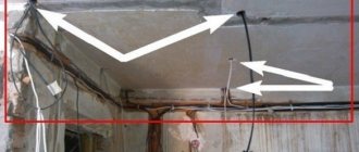
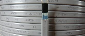
Installation of heat shrink sleeve
First you need to prepare the cable. The insulating armored shell is removed from its ends, right down to the conductive elements. The insulation from the cores is not removed at this stage. The length of cable cutting is determined by several factors:
- cable brand;
- cross-section, material of the conductor;
- number of cores, as well as other parameters specified in the reference books.
Next, prepare the coupling for installation:
- Place a heat shrink tube on the end of the cable.
- The grounding wire on the connecting and end couplings is secured with a special contact (without further soldering).
- The junction of the jumper with the armored shell is wrapped in sealing tape.
- For grounding jumpers, copper conductors with a 16 mm cross-section are used. If the cross-section of the cores is 120–240 sq. mm, install a 25 mm jumper.
- Place heat-shrinkable tubing onto the ends of the remaining cable wires.
- Connect phase conductors and neutral. The connection is made with crimp sleeves or bolts with a removable head.
- The wires are placed in the cells of the frame cassette and closed.
The cassette is joined to an external heat-shrinkable tube. Heating occurs, resulting in complete shrinkage. All connecting elements are available in coupling kits.
Clutch selection criteria
When choosing electric welded connection fittings, consider:
- type of connecting element;
- fitting dimensions;
- manufacturing company.
Types of electric welding fittings
The type of fitting is selected depending on the connection characteristics of the pipeline system and in accordance with the network diagram. Electrofusion fittings are intended for:
- for welding pipes at different angles;
- for connecting pipes of the same diameter;
- for fastening pipes of different diameters;
- to connect an additional outlet.
Selecting the type of electric welded coupling
Variety of sizes
The next parameter is the selection of overall dimensions of the connecting element. Overall dimensions mean:
- internal diameter (dn);
- outer diameter (de). ;
- fitting length (Z);
- length of one component of the fitting (L);
- distance to the terminal and from the terminal (f) to the edge of the coupling (a).
Main fitting sizes
Currently, couplings with diameters from 20 mm to 400 mm are produced. Pipe tying will be of better quality if the technical parameters of the fitting fully correspond to the parameters of the pipes being connected.
Manufacturers
To ensure the quality of the weld and the fitting used, it is recommended to select connecting elements from the most popular manufacturers, which include:
- Chiorino (Italy);
- Optibelt (Germany);
- Nupigeco (Italy);
- Ammeraal Beltech (Holland).
The products of these companies are made from high-quality materials in compliance with all norms and regulations, which allows us to achieve the maximum quality of electric welded fittings.
Common mistakes when installing couplings
Contaminated surfaces
The installation of a connecting element on a cable is often carried out in trenches or pits, where it is quite difficult to monitor the cleanliness of the working space. However, when working with couplings, additional protective agents in the form of films should be used. It is necessary to monitor the cleanliness of both tools and consumables, as well as remove contamination in a timely manner.
Violation of connector installation technology
The dimensions of connecting tubes and wires must comply with the requirements of the manufacturer. Otherwise, some defects may appear over time. They must be detected in advance and rubbed with a file, after which the area must be treated with a grinding wheel. Protruding elements of fasteners also need to be sanded. After completing this work, the resulting sawdust should be carefully removed.
Uneven thickness of cuff insulation
This problem can arise when shrinking a sleeve with thick walls using the heat shrink method. To avoid this, it is necessary to evenly heat the entire area to be treated. In some cases this is not possible due to working conditions.
The use of a bent tin reflector makes it possible to evenly distribute heat over the entire surface to ensure uniform heating of the adhesive composition present in the sealant and its uniform distribution.
Installed coupling
Broken coupling tightness
Parts that are installed on high-voltage power lines have three sealed zones:
- interfacial belt;
- internal (in the body);
- on the outer surface of the connection.
To shrink the external sealing belts, additional sealing agents are used to process the joints. After heat treatment, the adhesive composition should protrude beyond the edges of the joint and create a kind of barrier to prevent the ingress of harmful substances.
If the substance does not come out, it means that an error was made during this process. Also, before starting work on laying the assembled compound in the soil, it is necessary to carry out a thorough inspection to detect possible defects. If you find damage to the insulating layer, you need to install a repair sleeve with an adhesive base.
Air masses in couplings
Each cavity between the coupling elements must be filled with sealing material. If an air mass forms in the coupling body, the process of ion formation will undoubtedly begin.
To summarize, connecting elements for power lines must be installed according to strict guidelines and in compliance with certain rules. All actions must be carried out by specialists, since these operations require high qualifications and a decent amount of experience. It is not recommended to do this yourself.
Return to content
Scope of application of couplings
As a rule, cable couplings are used to form electrical networks, regardless of their purpose, and to connect networks of special electrical equipment.
Such products are composed of various parts and materials to ensure optimal branching or connection of electrical conductors and wires.
By reliably connecting cables, the coupling is an excellent element for both insulation and strong sealing.
The device is often used in various jobs, but most often this concerns laying cables over long distances.
Popular types of cable couplings and their features
There are several classifications of couplings. The most popular and most explanatory of why this or that option is required is for its intended purpose, which will be discussed below.
The design is divided into single- and three-phase. The section of materials used contains the following list:
- made of lead;
- epoxy resins;
- heat-shrinkable;
- cold shrinkage;
- cast iron;
- brass
The type of dielectric insulation also comes in several types: rubber, plastic and impregnated paper.
To understand its purpose in more detail, it is proposed to consider each type separately.
Couplings
The most popular type of couplings is connecting couplings, since power lines often have to be combined. The main task posed here is tightness. Couplings can be found either collapsible or not - it all depends on the task. The raw materials for production must be immune to external influences.
The coupling is needed to prevent the impregnating composition from draining, as well as to protect against damage in the area of joining multi- and single-core power cables.
End couplings
When compared with other types of devices, it turns out that the end one is not only a connecting link, but also a closing link. It is used to work with cables with paper impregnation, plastic or rubber insulation with a voltage of 1-35 kV.
The products provide maximum sealing, have excellent insulating properties, and are also resistant to chemically aggressive environments and the negative effects of natural phenomena. They operate stably at temperatures of -50…+50 degrees.
They note the speed of installation - the specialist spends little time and practically does not use special equipment. At the same time, the service life will be as long as possible, and the price costs will be affordable.
Stop couplings
The type of product under consideration is needed for the use of cable and wire products with impregnated paper insulation. The main task is to prevent the impregnating mass from flowing down when laying vertically or when the difference in height on the site exceeds the permissible one.
The locking coupling is used on cable routes with significant changes in laying levels due to the complexity of the terrain or urban structure. It is installed when the length of the laid line is over 2 kilometers.
Transition couplings
Since the cable network consists of wires of different types and modifications, adapters are indispensable. They are easy to use and resistant to mechanical damage. In fact, these are universal couplings that will fit most cables, regardless of the main characteristics. Therefore, the number of cores does not play a special role.
The design of the equipment allows the tension to be evenly distributed in the cut area of the semiconducting screen; for this, a special tube is used. Complete sealing and high mechanical strength during installation are guaranteed by the manufacturer.
Branch couplings
Specialized products require the use of branch couplings. They are required solely for branching the cable from the power trunk line. They are made from various materials, depending on the use.
The choice of configuration for any type of coupling depends on the electrical parameters of the cable being connected.
Cable couplings are an indispensable part in many situations related to working with the electrical network. To choose the right option for a specific task, it is necessary to study the types of couplings. This is not at all difficult to do - the above material is designed to help you with this.
Main types of couplings
Connecting
This type of coupling is the most common and is used when installing conductors, as well as for eliminating breaks on lines. From a structural point of view, there are monolithic devices and collapsible ones. Both types of connectors provide tightness, mechanical strength and resistance of the connection to aggressive environments.
The couplings are designed for conductors with paper or plastic insulation. One of the varieties of such devices - an adapter coupling - is connected to any cable, regardless of the type of insulating material.
Branch
This type of device is classified as a specialized type of fittings. They are used exclusively on power lines to route the cable in the desired direction.
Stopper
The task of the locking coupling is primarily to ensure the rigidity of all shell elements, including shielding and insulating ones.
The rigidity of the connection is necessary to avoid sliding of some parts of the cable under its own weight in those areas where the line is located vertically or at a large angle. The need for locking connectors is determined based on engineering analysis. Calculations are carried out taking into account many factors:
- the length of the cable running along an inclined path;
- strength of cable components;
- permitted loads;
- angle of inclination and other circumstances.
There is an additional type of locking connectors - lock-transition.
Heat-shrinkable sleeves
Installation of connectors with insulation made from heat-shrinkable tubes is not difficult, since the plastic components simplify the process of joining conductors. Installation takes approximately half the time compared to other types of connecting elements.
The polymer from which the connector is made, upon reaching a temperature of 150 degrees (use a gas burner or hair dryer), is compressed and reliably fastens the part being grasped. As a result, complete tightness of the connection is achieved. During the crimping process, air is removed from all cavities. As it cools, the material adheres to the elements of the power line, enveloping the surfaces. The service life of the connection reaches a quarter of a century.
Cold shrink couplings
This type of connection is based on elastomer technology, where a dielectric is applied to the product. Silicone is used as a dielectric base. The dielectric allows you to insulate the connection as efficiently as possible.
We advise you to study - Automation of technological processes
Installation is carried out at standard temperature. Warming is not used. Instead, cold shrink tension is applied.
The fittings for power cables with elastomer are located in the inner part of the spiral cord and are installed in their proper place. Next, the element is distributed over the entire commutation surface of the connection and pulled over the insulated area on both sides. After this, the cord is removed by rotating counterclockwise.
As a result of installation, the insulation completely covers the protected area. The method is often used in industrial buildings where there is an open fire or the threat of ignition.
End coupling
The electrical termination is designed to securely fix the ends of the conductor and ensure the tightness of its internal components. Used in switchboards, electrical equipment and other terminal systems.
Installation of various types of couplings
All HDPE coupling connections require preliminary preparation of plastic pipes. For the most durable and tight connection after cutting, they must be cleaned of dirt and burrs left behind by the cutting tool must be removed. It is also advisable to degrease the pipe.
Installation of couplings
To install the HDPE coupling, it is necessary to select a product of equal diameter to the pipe being connected. The connection algorithm looks like this:
- the plastic pipe is placed in the sleeve;
- The outer nut, previously placed on the pipe, is tightened clockwise as far as possible.
We recommend that you read: Rules for clearing blockages using a plumbing cable
Installation of compression couplings
To install a compression (crimp) coupling you must:
- unscrew the outer colored nut;
- place the nut behind the white ferrule;
- place the pipe into the coupling body, pushing the white ferrule all the way;
- Tighten the outer colored nut by hand or with a wrench until it stops.
Electric coupling installation
To connect pipes using an electric welded coupling, a special current supply device is required, which must activate the heating coil and melt the plastic at the junction. This could be a simple portable transformer or other device that creates direct current.
Installation algorithm:
- the fitting is put on top of the pipe;
- the coupling terminals are connected to a portable transformer;
- current from the switched on transformer is supplied to the thermal coil, which melts the polymer in a few minutes and creates a sealed joint.
After maintaining the required time for melting the polyethylene, you need to turn off the transformer and wait for the coupling to cool (on average this takes up to 20 minutes). It is not recommended to move it before the polymer hardens so as not to disturb the homogeneous structure of the fitting.
Steel pipe couplings
Connections for steel pipes come in several varieties; the simplest is a cylinder made of steel, cast iron, stainless steel or brass with an internal thread.
The disadvantage of this type is the need to rotate one of the sections of the connected pipe around its axis, so this type is used only when working with short sections.
To transition from internal to external threads, fittings are widely used - types of threaded fittings made in the form of a hex nut or bushing with a small diameter internal thread and a larger external thread.
Rice. 10 Couplings for metal and fittings
To join the ends of fixed pipes in a line, the following types of connections are used:
Sgon. The product is a piece of pipe with a double-sided external thread of different lengths; to connect the pipe ends, the bend is screwed into the pipe with a short thread, and the other end is connected using a coupling placed on the long threaded section. The coupling is screwed onto the external thread of the connected pipe and secured with a lock nut, wrapping a thick layer of tow into the place of fixation.
Compression coupling. Gebo couplings operate on the principle of metal-plastic compression fittings; their design includes a clamping ring with a slot, which is tightened with a union nut. Unlike fittings for cross-linked polyethylene, where the ring compresses and tightly seals the plastic polymer surface, in a metal product due to its rigidity this is not possible, so the Gebo design additionally includes a rubber sealing ring.
Rice. 11 Gebo design
Cast iron couplings for sewerage
When sewer pipes are made of cast iron, they are connected using a socket joint in the same way as PVC sewer pipes; a typical coupling is a piece of pipe with double-sided sockets. This type of coupling joint is sealed with rubber rings or caulking - the old-fashioned method, when hemp or flax rope impregnated with bitumen is pushed into the joint gap and then covered with cement mortar.
Incorrect connection methods
Having listed the correct ways to connect copper and aluminum wires, one cannot fail to mention what should not be done during electrical installation.
It is believed that if a copper conductor is tinned, its direct twisting with aluminum becomes possible. Opinions on this matter vary and most of them say that it is possible to connect copper wire to aluminum in this way. But there are still risks. The rules for tinning are simple and reliable only at first glance. Over time, the protective layer may begin to deteriorate, and it is almost impossible to control this process. That is why it is also better to abandon this method or use it only in the most extreme cases and for a short period of time.