AC Voltage Boost
Types of transformers
The simplest way to increase alternating voltage is to install a step-up transformer between the mains output and the supplied load. Devices used in practice are divided into two main types. The first is classical transformers, the second is autotransformers. Diagrams of these devices are shown in Figure 2.
Rice. 2. Transformer and autotransformer circuits
A classic transformer contains two windings: a primary or input winding with the number of turns W1, and a secondary or output winding with the number of turns W2. The rule for a transformer is Uoutput = K×Uinput, where K = W2/W1 is the transformation ratio. Thus, in a step-up transformer, the number of turns of the secondary winding exceeds that of the primary.
The step-up autotransformer contains a single winding with W2 turns. The network is connected to part W1 of its turns. The increase in U occurs due to the fact that the magnetic field created when current flows through the input part of the common winding induces current in the entire winding W2. The calculation formula for an autotransformer is similar to the usual one: Uoutput = K×Uinput, where K = W2/W1 is the transformation ratio.
Features of transformers
The operating efficiency of transformers is increased by using a core made of electrical steel. This component
- increases the efficiency of the device by reducing the scattering of the magnetic field in the surrounding space;
- performs the function of a supporting power base for the windings.
The inevitable losses due to eddy currents are reduced by the fact that the core is a stacked package of thin profiled insulated plates.
All other things being equal, it is advisable to use a transformer. This is due to the fact that it does not allow direct current to pass through, i.e. provides galvanic isolation of the network from the receiver, allowing for greater electrical safety.
A special feature of the transformer is its reversible nature, i.e. depending on the situation, it can equally successfully perform the functions of a step-up and step-down device. The only serious limitation is the need to comply with the normal operating modes of the primary and secondary windings.
Unlike computer sockets, called RJ45, different types of sockets are installed in different countries when installing household power supply networks. Known, for example, are sockets of German, French, English and other standards or styles. Therefore, it is advisable to assign the functions of an adapter to a low-power transformer, which, due to different types of plugs and sockets, ensures mechanical matching of the network and the load. An example of such a device is shown in Figure 3.
Rice. 3. An example of a reversible low-power transformer with the ability to match socket types
Laboratory autotransformers LATR
The strength of the autotransformer is the ease of regulating the output voltage by simply moving the current-collecting contact along the winding. Devices that allow this option are known as laboratory autotransformers LATR. They differ in their characteristic appearance due to the presence of a voltage regulator and a voltmeter for monitoring it, Figure 4.
LATRs are in demand not only in laboratories. They are widely used in garages, garden plots and other places where, due to overload and line wear, the voltage in the outlet is below the minimum permissible.
When the mains voltage fluctuates, instead of the usual LATR, it is advisable to use a stabilizer, where it is included in the form of one of the blocks.
Rice. 4. Appearance of one of the LATR variants
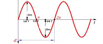
Periodic signals
A periodic signal is a signal whose shape repeats itself over time. Both the form of continuous signals and the form of discrete signals can be repeated in time. The signal period is the repetition interval.
For example, for a discrete signal y[n] the shape is repeated every 4, 8, 12 and so on reports, for a continuous signal z[t] the shape is repeated every 2, 4, 6 and so on seconds.
The fundamental or main period of a signal is the smallest repetition interval, that is, for our discrete signal y[n] it is 4 reports, and for our continuous signal it is two seconds.
DC Voltage Boost
The general principle of increasing DC voltage by an arbitrary number of times
The transformer method of increasing voltage cannot be used in DC networks. Therefore, if it is necessary to solve this problem, more complex devices are used, the operation of which is based on the following circuit: a constant input current is used to power a generator, from the output of which an alternating signal is removed. The alternating voltage is increased in one way or another, after which it is rectified and smoothed to obtain a higher constant voltage.
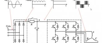
The block diagram of such a converter is shown in Figure 5.
Figure 5. General block diagram of a boost converter
Certain types of schemes differ from each other:
- the shape of the signal taken from the output of the generator (sinusoidal or close to it, sawtooth, pulse, etc.);
- the principle of increasing the generated voltage (transformer, multiplier);
- type of rectification and smoothing of voltage before applying it to the output of the device.
Continuous and discrete signals:
A continuous analog signal is defined over the entire period of time, that is, at any time t we can find out the value of the signal x. If we take these values with a sampling period T, then we get a discrete signal, the value of which is determined only at specific points in time.
The discrete signal is now written as x[n], and n is the report numbers of the discrete sequence. If we look at the sampling process from the point of view of mathematics, then the output discrete sequence with x[n] is formed when we substitute into our function x(t) a time value t equal to nT, where n is the number of the discrete report, and T is the period sampling.
Safety precautions
When assembling and using boosting devices, regardless of their type, it is necessary to comply with the basic provisions of safety regulations. The main ones:
- under no circumstances should you touch current-carrying circuit elements with unprotected parts of your body;
- even short-term exceeding of the maximum load is prohibited;
- devices in a regular office design cannot be used in wet areas;
- The equipment should be protected from splashing water.
Fundamental Frequency
From the concept of fundamental period we can move on to the concept of fundamental frequency. The fundamental or fundamental frequency, also called the first harmonic , is the number of fundamental signal periods per unit time. Frequency is measured in Hertz, that is, in the number of periods per second, and is actually the reciprocal of the main period.
If we consider our continuous signal z[t] its fundamental period is two seconds, which means that one second accounts for exactly half of its period.
Changing the sample rate
If we consider our manipulations on a discrete signal as manipulations on an analog signal, and after that the sampling of the analog signal, then this is what we come to. When we increase the sampling rate, we are actually taking the sampled records of a faster analog signal, or putting the records of the same sampled signal on a different time grid.
For example, our discrete signal with a sampling period ∆t can be represented as the digitized values of an analog signal with a period T0,
If we now put the same signal records on a denser time grid with a smaller period ∆t, this is actually the same as if we digitized a faster analog signal with a smaller period T0.
We introduced the sine wave as a reference, analog signal, and why do we use the sine wave so often when we talk about digital signal processing? This will be discussed in the next article.
Fundamental frequency of a discrete signal
But if with a continuous signal everything is more or less clear, that is, we can look at it on the time axis, estimate the values of the main period and calculate the value of the main frequency, then with a discrete signal everything is not so simple.
The meaning of the reports is available to us, we know their numbers in the sequence, but we do not know how they relate to its fundamental frequency, and how they relate to the sampling frequency. Let's try to figure this out with an example.
Let's take a discrete signal, which we use for description in previous articles. It has a period of 4 reports, where the first two reports in the period have a large amplitude, and the last two reports have a small amplitude.
Our task in this example will be to use such a signal to hear the note A of the first octave, that is, the frequency of 440 Hz. In order to do this, we definitely need to understand how the fundamental frequency relates to the signal sampling frequency.
To do this, let's transfer our signal to the time axis. The fundamental period of this signal is calculated in the same way as for a continuous signal, that is, it is the reciprocal of its fundamental frequency, in our case, units divided by 440. But we also see that the sampling period of our signal, let us denote it here as ∆t 4 times less than the main period, since the main period accounts for exactly 4 samples.
Let's express the sampling frequency through the sampling period, the sampling frequency can be written as one divided by ∆t, which is equal to 4 divided by T0, that is, in our case, the sampling frequency should be 4 times greater than our fundamental frequency of the A note of the first octave.