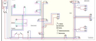
In order to ensure the supply of voltage from the distribution device to the end consumer, power lines are used. They can be overhead or cable and have a considerable length.
Like all conductors, they have a resistance that depends on the length and the longer they are, the greater the voltage loss.
And the longer the line, the greater the voltage loss will be. Those. The voltage at the input and at the end of the line will be different.
In order for the equipment to operate without failures, these losses are normalized. Their total value should not exceed 9%.
The maximum voltage drop at the input is five percent, and to the most remote consumer no more than four percent. In a three-phase network with a three or four wire network, this figure should not exceed 10%.
Symptoms of low voltage in a consumer
If these indicators are not met, end users will not be able to provide the nominal parameters. When the voltage decreases, the following symptoms occur:
- Lighting devices that use incandescent lamps begin to work (glow) at half incandescence;
- When the electric motors are turned on, the starting force on the shaft decreases. As a result, the motor does not rotate, and as a result, the windings overheat and fail;
- Some electrical appliances do not turn on. There is not enough voltage, and other devices may fail after switching on;
- Installations that are sensitive to input voltage are unstable, and light sources that do not have an incandescent filament may also not turn on.
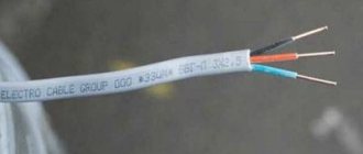
Electricity is transmitted via overhead or cable networks. Overhead ones are made of aluminum, while cable ones can be aluminum or copper.
In addition to active resistance, cables contain capacitive reactance. Therefore, the power loss depends on the cable length.
Reasons leading to a decrease in voltage
Voltage losses in power lines occur for the following reasons:
- A current passes through the wire, which heats it, as a result, the active and capacitive resistance increases;
- A three-phase cable with a symmetrical load has the same voltage values on the cores, and the neutral wire current will tend to zero. This is true if the load is constant and purely active, which is impossible in real conditions;
- In networks, in addition to the active load, there is a reactive load in the form of transformer windings, reactors, etc. and as a result, inductive power appears in them;
- As a result, the resistance will consist of active, capacitive and inductive. It affects voltage losses in the network.
Current losses depend on the cable length. The longer it is, the greater the resistance, which means that the losses are greater. It follows that power losses in a cable depend on the length or length of the line.
Electricity losses in electrical networks: types, causes, calculation
Electricity losses in electrical networks are inevitable, so it is important that they do not exceed an economically justified level.
Exceeding technological consumption standards indicates problems that have arisen. To correct the situation, it is necessary to establish the causes of non-target costs and choose ways to reduce them.
The information collected in this article describes many aspects of this difficult task.
Types and structure of losses
Losses mean the difference between the electricity supplied to consumers and the energy actually received by them. To normalize losses and calculate their actual value, the following classification was adopted:
- Technological factor. It directly depends on characteristic physical processes, and can change under the influence of the load component, semi-fixed costs, as well as climatic conditions.
- Costs spent on operating auxiliary equipment and providing the necessary conditions for the work of technical personnel.
- Commercial component. This category includes errors in metering devices, as well as other factors causing under-metering of electricity.
Below is an average graph of losses for a typical electric company.
Approximate loss structure
As can be seen from the graph, the highest costs are associated with transmission via overhead lines (power lines), this accounts for about 64% of the total losses. In second place is the corona effect (ionization of air near the overhead line wires and, as a consequence, the occurrence of discharge currents between them) – 17%.
Corona discharge on a power line insulator
Based on the presented graph, it can be stated that the largest percentage of non-targeted expenses falls on the technological factor.
Main causes of electricity losses
Having understood the structure, let's move on to the reasons that cause inappropriate expenditure in each of the categories listed above. Let's start with the components of the technological factor:
- Load losses occur in power lines, equipment and various elements of electrical networks. Such costs directly depend on the total load. This component includes:
- Losses in power lines are directly related to current strength. That is why, when transmitting electricity over long distances, the principle of increasing it several times is used, which contributes to a proportional reduction in current and, accordingly, costs.
- Consumption in transformers of a magnetic and electrical nature (1). As an example, below is a table that shows cost data for substation voltage transformers in 10 kV networks.
Losses in power transformers of substations
Non-target consumption in other elements is not included in this category due to the complexity of such calculations and the insignificant amount of costs. For this, the following component is provided.
- Category of semi-fixed expenses. It includes costs associated with the normal operation of electrical equipment, these include:
- Idle operation of power plants.
- Costs in equipment providing reactive load compensation.
- Other types of costs in various devices, the characteristics of which do not depend on the load. Examples include power insulation, metering devices in 0.38 kV networks, measuring current transformers, surge limiters, etc.
- Climatic component. Inappropriate consumption of electricity may be associated with climatic conditions characteristic of the area where power lines pass. In networks of 6 kV and higher, the magnitude of the leakage current in the insulators depends on this. In main lines from 110 kV, a large share of the costs falls on corona discharges, the occurrence of which is facilitated by air humidity. In addition, in the cold season, our climate is characterized by such a phenomenon as icing on the wires of high-voltage lines, as well as ordinary power lines. Ice on power lines
Taking into account the last factor, the energy costs for melting ice should be taken into account.
Costs for supporting the operation of substations
This category includes the cost of electrical energy for the operation of auxiliary devices. Such equipment is necessary for the normal operation of the main units responsible for the conversion of electricity and its distribution. Costs are recorded using metering devices. Here is a list of the main consumers belonging to this category:
- ventilation and cooling systems for transformer equipment;
- heating and ventilation of the technological room, as well as internal lighting fixtures;
- lighting of areas adjacent to substations;
- battery charging equipment;
- operational circuits and monitoring and control systems;
- outdoor equipment heating systems, such as air circuit breaker control modules;
- various types of compressor equipment;
- auxiliary mechanisms;
- equipment for repair work, communication equipment, as well as other devices.
Commercial component
These costs mean the balance between absolute (actual) and technical losses. Ideally, such a difference should tend to zero, but in practice this is not realistic.
This is primarily due to the characteristics of electricity meters and electricity meters installed at end consumers. It's about error.
There are a number of specific measures to reduce losses of this type.
https://www.youtube.com/watch?v=BSu1WKe6bEo
This component also includes errors in bills issued to consumers and theft of electricity. In the first case, a similar situation may arise for the following reasons:
- the contract for the supply of electricity contains incomplete or incorrect information about the consumer;
- incorrectly indicated tariff;
- lack of control over meter data;
- errors related to previously adjusted accounts, etc.
As for theft, this problem occurs in all countries. As a rule, such illegal actions are carried out by unscrupulous household consumers.
Note that sometimes incidents occur with enterprises, but such cases are quite rare, and therefore are not decisive.
It is typical that the peak of thefts occurs in the cold season, and in those regions where there are problems with heat supply.
There are three methods of theft (understating meter readings):
- Mechanical . This means appropriate intervention in the operation of the device. This can be slowing down the rotation of the disk by direct mechanical action, changing the position of the electric meter by tilting it by 45° (for the same purpose). Sometimes a more barbaric method is used, namely, the seals are broken and the mechanism is unbalanced. An experienced specialist will instantly detect mechanical interference.
- Electric . This can be an illegal connection to an overhead line by “throwing”, a method of investing a phase of the load current, as well as the use of special devices for its full or partial compensation. In addition, there are options with shunting the current circuit of the meter or switching phase and zero.
- Magnetic . With this method, a neodymium magnet is brought to the body of the induction meter.
The magnet can only affect some older models of electricity meters
Almost all modern metering devices cannot be “deceived” using the methods described above. Moreover, such attempts to interfere can be recorded by the device and stored in memory, which will lead to dire consequences.
The concept of loss standard
This term means the establishment of economically sound criteria for non-target expenditure for a certain period. When standardizing, all components are taken into account. Each of them is carefully analyzed separately.
As a result, calculations are made taking into account the actual (absolute) level of costs for the past period and an analysis of various opportunities that make it possible to realize the identified reserves to reduce losses.
That is, the standards are not static, but are regularly revised.
The absolute level of costs in this case means the balance between the transferred electricity and technical (relative) losses. Technological loss standards are determined by appropriate calculations.
Who pays for lost electricity?
It all depends on the defining criteria. If we are talking about technological factors and costs of supporting the operation of related equipment, then payment for losses is included in the tariffs for consumers.
The situation is completely different with the commercial component; if the established loss rate is exceeded, the entire economic load is considered an expense for the company that supplies electricity to consumers.
Ways to reduce losses in electrical networks
Costs can be reduced by optimizing the technical and commercial components. In the first case, the following measures should be taken:
- Optimization of the circuit and operating mode of the electrical network.
- Study of static stability and identification of powerful load nodes.
- Reduction of total power due to the reactive component. As a result, the share of active power will increase, which will have a positive impact on the fight against losses.
- Transformer load optimization.
- Equipment modernization.
- Various load balancing methods. For example, this can be done by introducing a multi-tariff payment system, in which the cost of kWh is increased during peak load hours. This will significantly reduce the consumption of electricity during certain periods of the day; as a result, the actual voltage will not “sag” below acceptable standards.
You can reduce your business costs by:
- regular search for unauthorized connections;
- creation or expansion of units exercising control;
- checking readings;
- automation of data collection and processing.
Methodology and example for calculating electricity losses
In practice, the following methods are used to determine losses:
- carrying out operational calculations;
- daily criterion;
- calculation of average loads;
- analysis of the greatest losses of transmitted power by day and hour;
- access to generalized data.
Full information on each of the methods presented above can be found in regulatory documents.
https://www.youtube.com/watch?v=BSu1WKe6bEou0026t=131s
In conclusion, we give an example of calculating costs in a TM 630-6-0.4 power transformer. The calculation formula and its description are given below; it is suitable for most types of similar devices.
Calculation of losses in a power transformer
To understand the process, you should familiarize yourself with the main characteristics of TM 630-6-0.4.
Parameters TM 630/6/0.4
Now let's move on to the calculation.
Calculation results
List of used literature
- Y. Zhelezko “Electricity losses. Reactive power. Power Quality: A Guide for Practical Calculations" 2009
- Pospelov G.E. “Power and energy losses in electrical networks” 1981
- Shvedov G.V., Sipacheva O.V.
, Savchenko O.V. “Losses of electricity during its transport through electrical networks: calculation, analysis, regulation and reduction” 2013 - Fursanov M.I.
“Definition and analysis of electricity losses in electrical networks of power systems” 2005
Loss Value Calculation
To ensure the operability of the equipment, it is necessary to make a calculation. It is carried out at the time of design. The current level of development of computer technology allows calculations to be made using an online calculator, which allows you to quickly calculate cable power losses.
To calculate, just enter the required data. Set the current parameters - direct or alternating. The power line material is aluminum or copper. Indicate by what parameters the power loss is calculated - by cross-section or diameter of the wire, load current or resistance.
Additionally, indicate the network voltage and cable temperature (depending on operating conditions and installation method). These values are inserted into the calculation table and calculated using an electronic calculator.
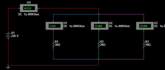
You can make a calculation based on mathematical formulas. In order to correctly understand and evaluate the processes occurring during the transmission of electrical energy, a vector form of representing characteristics is used.
And to minimize calculations, a three-phase network is represented as three single-phase networks. Network resistance is represented as a series connection of active and reactive resistance to the load resistance.
In this case, the formula for calculating power loss in a cable is significantly simplified. To obtain the necessary parameters, use the formula.
∆U= I*RL.
This formula shows the power loss of a cable as a function of the current and resistance distributed along the length of the cable.
However, this formula is valid if you know the current strength and resistance. Resistance can be calculated using the formula. For copper it will be equal to p=0.0175 Ohm*mm2/m, and for aluminum p=0.028 Ohm*mm2/m.
Knowing the value of resistivity, calculate the resistance, which will be determined by the formula
R=р*I/S, where р is resistivity, I is line length, S is cross-sectional area of the wire.
In order to calculate voltage losses along the cable length, you need to substitute the obtained values into the formula and perform calculations. These calculations can be made when installing electrical networks or security systems and video surveillance.
If power loss calculations are not made, this may lead to a decrease in the supply voltage to consumers. As a result, the cable will overheat, it may become very hot, and as a result, the insulation will be damaged.
Which may cause electric shock or short circuit to people. A decrease in line voltage can lead to failure of electronic equipment.
Therefore, when designing electrical wiring, it is important to calculate the voltage loss in the supply wires and the laid cable.
Cable loss calculation
During operation, the conductors heat up and generate heat. The higher the voltage and resistance of the cores, the greater the losses in the cable.
Losses can be calculated using the formula: ΔU=(Unom-U)∙100/ Unom, where: Unom is the rated voltage at the cable input, U is the voltage supplied to the load. Losses are indicated as a percentage of the rated voltage.
To avoid errors in calculations, it is customary to use Knorring tables based on the relationship between the power of the current load and the length of the power line.
Table 1 Voltage 220 V
| ΔU, % | Load moment for copper conductors, kW∙m, two-wire lines for voltage 220 V | |||||
| With conductor cross section s, mm2, equal to | ||||||
| 1,5 | 2,5 | 4 | 6 | 10 | 16 | |
| 0,2 | 4 | 6 | 10 | 14 | 24 | 38 |
| 0,4 | 7 | 12 | 19 | 29 | 48 | 77 |
| 0,6 | 11 | 18 | 29 | 43 | 72 | 115 |
| 0,8 | 14 | 24 | 38 | 58 | 96 | 154 |
| 1 | 18 | 30 | 48 | 72 | 120 | 192 |
| 1,2 | 22 | 36 | 58 | 86 | 144 | 230 |
| 1,4 | 25 | 42 | 67 | 101 | 168 | 269 |
| 1,6 | 29 | 48 | 77 | 115 | 192 | 304 |
| 1,8 | 32 | 54 | 86 | 130 | 216 | 346 |
| 2 | 36 | 60 | 96 | 144 | 240 | 384 |
| 2,2 | 40 | 66 | 106 | 158 | 264 | 422 |
| 2,4 | 43 | 72 | 115 | 173 | 288 | 461 |
| 2,6 | 47 | 78 | 125 | 187 | 312 | 499 |
| 2,8 | 50 | 84 | 134 | 202 | 336 | 538 |
| 3 | 54 | 90 | 144 | 216 | 360 | 576 |
| 3,2 | 58 | 96 | 154 | 230 | 384 | 614 |
| 3,4 | 61 | 102 | 163 | 245 | 408 | 653 |
| 3,6 | 65 | 108 | 173 | 259 | 432 | 691 |
| 3,8 | 68 | 144 | 182 | 274 | 456 | 730 |
| 4 | 72 | 120 | 192 | 288 | 480 | 768 |
| 4,2 | 76 | 126 | 202 | 302 | 504 | 806 |
| 4,4 | 79 | 132 | 211 | 317 | 528 | 845 |
| 4,6 | 83 | 138 | 221 | 331 | 552 | 883 |
| 4,8 | 86 | 144 | 230 | 346 | 576 | 922 |
| 5 | 90 | 150 | 240 | 360 | 600 | 960 |
Table 2 Voltage 380/220 V for three-phase and four-phase lines. When there is a difference in loads in the lines, calculations are made according to Table 1.
| ΔU, % | Load moment for copper conductors, kW∙m, four-wire three-phase lines with zero for voltage 380/220 V or three-wire three-phase without zero for 380 V with conductor cross-section s, mm2 equal | |||||||||||||
| 1.5 | 2,5 | 4 | 6 | 10 | 16 | 25 | 35 | 50 | 70 | 95 | 120 | 150 | 185 | |
| 0,2 | 22 | 36 | 58 | 86 | 144 | 230 | 360 | 504 | 720 | 1 008 | 1 368 | 1 728 | 2 160 | 2 664 |
| 0,4 | 43 | 72 | 115 | 173 | 288 | 461 | 720 | 1 008 | 1 440 | 2 016 | 2 736 | 3 456 | 4 320 | 5 328 |
| 0,6 | 65 | 108 | 173 | 259 | 432 | 691 | 1 080 | 1 512 | 2 160 | 3 024 | 4 104 | 5 184 | 6 480 | 7 992 |
| 0,8 | 86 | 144 | 230 | 346 | 576 | 922 | 1 440 | 2 016 | 2 880 | 4 032 | 5 472 | 6 912 | 8 640 | 10 656 |
| 1 | 108 | 180 | 288 | 432 | 720 | 1 152 | 1 800 | 2 520 | 3 600 | 5 040 | 6 840 | 8 640 | 10 800 | 13 320 |
| 1,2 | 130 | 216 | 346 | 518 | 864 | 1 382 | 2 160 | 3 024 | 4 320 | 6 048 | 8 208 | 10 368 | 12 960 | 15 984 |
| 1,4 | 151 | 252 | 403 | 605 | 1 008 | 1 613 | 2 520 | 3 528 | 5 040 | 7 056 | 9 576 | 12 096 | 15 120 | 18 648 |
| 1,6 | 173 | 288 | 462 | 691 | 1 152 | 1 843 | 2 880 | 4 032 | 5 760 | 8 064 | 10 944 | 13 824 | 17 280 | 21 312 |
| 1,8 | 194 | 324 | 518 | 778 | 1 296 | 2 074 | 3 240 | 4 536 | 6 480 | 9 072 | 12 312 | 15 552 | 19 440 | 23 976 |
| 2 | 216 | 360 | 576 | 864 | 1 440 | 2 304 | 3 600 | 5 040 | 7 200 | 10 080 | 13 680 | 17 280 | 21 600 | 26 640 |
| 2,2 | 238 | 396 | 636 | 950 | 1 584 | 2 534 | 3 960 | 5 544 | 7 920 | 11 088 | 15 048 | 19 008 | 23 760 | 29 304 |
| 2,4 | 259 | 432 | 691 | 1 037 | 1 728 | 2 765 | 4 320 | 6 048 | 8 640 | 12 096 | 16 416 | 20 736 | 25 920 | 31 968 |
| 2,6 | 281 | 478 | 749 | 1 121 | 1 872 | 2 995 | 4 780 | 6 552 | 9 360 | 13 104 | 17 784 | 22 464 | 28 100 | 34 632 |
| 2,8 | 302 | 504 | 806 | 1 210 | 2 016 | 3 226 | 5 040 | 7 056 | 10 080 | 14 112 | 19 152 | 24 192 | 30 200 | 37 296 |
| 3 | 324 | 540 | 864 | 1 296 | 2 160 | 3 456 | 5 400 | 7 560 | 10 800 | 15 120 | 20 520 | 25 920 | 32 400 | 39 960 |
| 3,2 | 346 | 576 | 922 | 1 386 | 2 304 | 3 686 | 5 760 | 8 064 | 11 520 | 16 128 | 21 888 | 27 648 | 34 560 | 42 624 |
| 3,4 | 367 | 612 | 979 | 1 469 | 2 448 | 3 917 | 6 120 | 8 568 | 12 240 | 17 136 | 23 256 | 29 376 | 36 720 | 45 280 |
| 3,6 | 389 | 648 | 1 037 | 1 555 | 2 592 | 4 147 | 6 480 | 9 072 | 12 960 | 18 144 | 24 624 | 31 104 | 38 880 | 47 952 |
| 3,8 | 410 | 684 | 1 094 | 1 642 | 2 736 | 4 378 | 6 840 | 9 576 | 13 680 | 19 152 | 25 992 | 32 832 | 41 040 | 50 616 |
| 4 | 432 | 720 | 1 152 | 1 728 | 2 880 | 4 608 | 7 200 | 10 080 | 14 400 | 20 160 | 27 360 | 34 560 | 43 200 | 53 280 |
| 4,2 | 454 | 756 | 1 210 | 1 814 | 3 024 | 4 838 | 7 560 | 10 584 | 15 120 | 21 168 | 28 728 | 36 288 | 45 360 | 55 944 |
| 4,4 | 475 | 792 | 1 267 | 1 901 | 3 168 | 5 069 | 7 920 | 11 088 | 15 840 | 22 176 | 30 096 | 38 016 | 47 520 | 58 608 |
| 4,6 | 497 | 828 | 1 325 | 1 987 | 3 321 | 5 299 | 8 280 | 11 592 | 16 560 | 23 184 | 31 464 | 39 744 | 49 680 | 61 272 |
| 4,8 | 518 | 864 | 1 382 | 2 074 | 3 454 | 5 530 | 8 640 | 12 096 | 17 280 | 24 192 | 32 832 | 41 472 | 51 840 | 63 936 |
| 5 | 540 | 900 | 1 440 | 2 160 | 3 600 | 5 760 | 9 000 | 12 600 | 18 000 | 25 200 | 34 200 | 43 200 | 54 000 | 66 600 |
Table 3 Voltage 12 W (copper conductor, line of two wires)
| ΔU, % | Load moment for copper conductors, kW∙m, two-wire lines for 12 V voltage | |||||
| With conductor cross section s, mm2, equal to | ||||||
| 1,5 | 2,5 | 4 | 6 | 10 | 16 | |
| 1 | 0,05 | 0,09 | 0,14 | 0,22 | 0,36 | 0,58 |
| 2 | 0,1 | 0,18 | 0,29 | 0,43 | 0,72 | 1,15 |
| 3 | 0,16 | 0,27 | 0,43 | 0,65 | 1,08 | 1,73 |
| 4 | 0,22 | 0.36 | 0,58 | 0,86 | 1,44 | 2,3 |
| 5 | 0.27 | 0,45 | 0,72 | 1,08 | 1,8 | 2,88 |
| 6 | 0,32 | 0,54 | 0,86 | 1,3 | 2,16 | 3,46 |
| 7 | 0,38 | 0,63 | 1,0 | 1,51 | 2,52 | 4,03 |
| 8 | 0,44 | 0,72 | 1,16 | 1,72 | 2,88 | 4,6 |
| 9 | 0,49 | 0,81 | 1,3 | 1,94 | 3,24 | 5,18 |
| 10 | 0,54 | 0,9 | 1,44 | 2,16 | 3,6 | 5,76 |
Optimal operation of the power cable is possible with a loss of no more than 5%.
If the resulting figure is higher, it is necessary to replace the cable with a larger cross-sectional area of the conductor. Otherwise, the system will not work, and the likelihood of a short circuit also increases. It is also not worth buying a power cable with a larger cross-section than necessary. This significantly increases the cost of operating networks. When choosing a cable, be guided by the indicators obtained during calculations.
Loss reduction methods
Power losses can be reduced by the following methods:
- Increase the cross-section of conductors. As a result, resistance will decrease and losses will decrease;
- Reduced power consumption. This setting cannot always be changed;
- Changing the cable length.
Reducing power and changing line length is practically impossible. Therefore, if you increase the cross-section of the wire without calculation, then on a long line this will lead to unjustified costs.
This means that it is very important to make a calculation that will allow you to correctly calculate the power losses in the cable and select the optimal cross-section of the cores.