Why do grounding in a private house?
The operation of electrical appliances in a residential building is accompanied by the risk of short circuits or damage to the insulating coating of the wires. Such areas are dangerous to human life. If he touches faulty electrical equipment, he will receive an electric shock because... the body is a good conductor.
Therefore, for the safety of residents, all country cottages must be equipped with grounding devices, which also prevent premature failure of household electrical appliances.
Standards of PUE grounding
Grounding PUE standards are a set of regulatory legal acts. These rules include recommendations on how to carry out electrical wiring correctly, a description of various electrical installations and the principle of their operation, as well as the requirements for electrical systems and their components.
Grounding installation work must be carried out in accordance with the electrical installation regulations. The criteria defined in the PUE will allow all connections to be made without errors, maintaining all standards. This guarantees reliable operation of the protective system in the house and will avoid the negative consequences of natural and man-made impacts.
If you unquestioningly follow all the rules described in the PUE, this will lead to large financial costs, so electricians and engineers follow only very important recommendations in their activities.
In accordance with the rules of the PUE, a repeated protective circuit must certainly be located at the exit areas from the premises. It is recommended to install natural grounding electrodes at this location. These include reinforced concrete devices, large metal parts, which for the most part are directly connected to the ground.
The PUE also specifies items that cannot be used as grounding conductors: energized metal objects, sewer and heating pipes, as well as pipelines with flammable substances.
Ground loop device
The ground loop is made up of several electrodes that are connected to each other by a metal rod and buried in the ground. Such designs most often have a square or triangular shape.
Pin installation depth
Vertical grounding pins are driven into the ground to a depth of 0.6 m, but not higher than the freezing level. A distance of 2.5 to 3 m is left between them. At the bottom of the trench, the ends of the electrodes are connected with a steel plate.
Why can't you put separate
According to the PUE, it is prohibited to ground private residential buildings using 1 pin.
There is such a thing as “flow resistance”. Around a rod buried in the ground, maximum voltage and electric current density are created. When it passes through the ground, the resistance to its movement increases, which stops after a set distance. This point is called the spreading zone.
One electrode provides a small area and slow spreading of electric current, so a minimum of 2-3 pins are used in grounding structures.
Initial data for calculating grounding
Before starting the arrangement of grounding, the calculation of which needs to be carried out, it is necessary to decide in advance on such initial data as:
- Linear dimensions of steel pins driven into the ground.
- The distance between them (installation pitch).
- Permissible immersion depth.
- Characteristics of the soil at the grounding site.
Additional note: Before carrying out the calculation, you will also need to know the value of the soil resistance Ohm at the installation site.
When determining it, it is important to remember that it varies greatly from place to place and largely depends on the climate zone to which the region belongs. In addition to these data, you will have to take into account the configuration and material of the workpieces from which the finished structure is welded (either a regular steel corner or a wide copper strip).
According to the PUE, the minimum dimensions of elements for a triangular or linear contour structure should be:
- strip - section 48 mm2;
- corner 4x4 mm;
- round bar – cross-section 10 mm2;
- steel pipe with a diameter of 2.5 cm with walls at least 3.5 mm thick.
Useful note: The minimum length of the pins is calculated taking into account the technical requirements (the need to obtain the required resistance to drainage into the ground).
In accordance with these requirements, it is chosen to be at least 2-2.5 meters. The distance between adjacent immersion points of the rods must be a multiple of their length. Depending on the size and configuration of the site for arranging the storage unit, the structural elements are installed either in a row or in the form of a regular triangle (sometimes a square shape is chosen for this). The methods used in this case for calculating various charger options aim to obtain data on the number of rods and the parameters of the connecting strip (its length and cross-section).
Grounding standards for a private home
Requirements for the arrangement of grounding of country cottages:
- The distance between a residential building and the external contour of the device is from 1 to 10 m. Recommended is from 2 to 4 m.
- The depth of the pins is 2-3 m. Part of the rod (0.2-0.25 m) is left on the surface for connection with a steel plate.
- The minimum cross-section of the bus that is laid to the triangle from the input electrical panel is 16 mm².
- To connect the elements of the grounding structure on the shield, bolts are used. The electrodes are connected with a strip of metal using welding.
- The maximum value of the design resistance is when using a 220 V network - 8 Ohms, 380 V - 4 Ohms.
Inner circuit routing
Electrical equipment that must be grounded is located throughout the entire area of the production premises. It is connected to the grounding system by laying busbars inside the building. The installation of grounding conductors is done openly; there should always be free access to them for control and inspection. The exception is metal pipes for hidden electrical wiring and explosive installations, where openings are sealed with easily knocked out non-combustible materials.
The grounding strips of the internal circuit should be laid horizontally or vertically. Only if the building includes inclined structures, it is allowed to lay conductors parallel to them. The internal grounding loop is mounted using walls and ceilings; if it is necessary to lay it on the floor, the grounding strip is laid in channels. Rectangular conductors are mounted with a wide plane to the wall. The strip is fastened to brick and concrete surfaces by driving nails using a construction gun. Screws are used for fixing to wooden walls.
The grounding conductors are connected to each other by welding. With strong heating, the protective zinc coating evaporates, thereby reducing the resistance of the steel to external influences. Therefore, the connection points are treated with zinc spray or enamel. In places where the resistance of the grounding device is to be measured, the conductor is bolted. It should be removable, but only with a tool. The attachment points of the grounding strips should be at a distance of 650 mm to 1000 mm from each other. The larger the cross-section of the strip, the more frequently they are located.
The structure of a building may include expansion joints that protect it from deformation. The grounding strip crossing such a joint must have a compensating bend. Through walls and ceilings, the grounding strip is freely passed through openings or enclosed in a steel pipe.
Types of ground loops
To instantly drain the electric current into the ground, the subsystem distributes it into several electrodes, which are located at a distance from each other. This allows you to increase the dispersion area. There are 2 options for making grounding.
Linear
In this case, 2-3 electrodes are placed in a semicircle or in a line. Such a contour is used if the area of the land plot does not allow for a closed structure.
Triangle
In this case, use 3 pins and connect them together with metal strips. The finished product is in the shape of a triangle with equal sides.
Example of grounding calculation
As a “classical” example of calculating grounding, let’s consider a charger option taking into account the given initial data, that is, we will carry out calculations for a single metal pin. Let us immediately make a reservation that such simple designs are used when organizing the re-grounding of high-voltage supports. In the situation under consideration, according to the provisions of the PUE (see clause 1.7.103.), the current flow resistance cannot be more than 15, 30 and 60 Ohms for voltages of 660, 380 and 220 Volts, respectively.
Calculation of a single grounding element for a 380 Volt overhead line support
According to the previously discussed method, first, using the table, select the type of vertical pin with the following characteristics:
- Material – steel.
- Shape: round rod with a diameter of 16 mm.
- Length L - 2.5 meters.
Please note: Semi-solid clay with a resistivity ρ equal to 60 Ohm per meter is selected as soil in accordance with the table.
The depth of the trench is taken to be half a meter. Then, from the same table, the correction factor entered for the average climatic zone is found. Its value for the actual length of the rods is up to 2.5 meters, taking into account soil freezing in the given area, is ψ = 1.45. The normalized resistance indicator for this type of charger is 30 Ohms. The next indicator, soil resistivity, is found by the formula:
ρ (in fact) = ψ•ρ = 1.45x60 = 87 Ohm•meter
The resulting calculated data looks like this:
- the penetration of a single pin into the ground is h = 0.5l + t = 0.5x2.5 + 0.5 = 1.75 meters;
- its resistance for our example (see formulas above) is no more than 30 Ohms, which corresponds to the requirements of the PUE for a given voltage.
When one grounding pin is not enough to support an overhead line, it is allowed to add one more or even several rods. In this case, a different technique will be required, used for a linear outline or a triangular design.
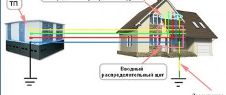
Grounding schemes: which one to choose
The grounding system of a country cottage depends on the type of network connection to it. The TN-C principle is often used. At a voltage of 220V, the mains voltage is provided by an overhead two-wire line or a two-wire cable. At 380V, a four-wire line or four-wire cable is used.
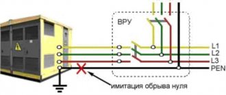
TN-CS
In this case, the PEN input is divided into parallel conductors.
The PEN conductor, located in the input cabinet, is divided into 3 buses:
- neutral – N;
- earth - RE;
- distributor for 4 connections.
The N bus is placed on insulators, the PE is connected to the body of the input cabinet. The conductors do not contact each other. A circuit is connected to the distributor. The ground electrode is connected by a copper jumper with a cross-section of 10 mm² to the N bus.
TT
In this case, the tires are not split in the input panel, because neutral and ground are already separated in the network. Only the PE conductor is connected to the ground electrode.
Ground Measurement
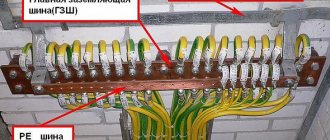
Grounding circuit: PUE standards
To measure grounding resistance, special measuring instruments are used. Organizations with the appropriate permit have the right to measure grounding. Typically these are energy organizations and laboratories. The measured parameters are entered into the measurement protocol and stored at the enterprise (in the workshop, at the substation).
Ground Measuring Instrument
Calculating grounding resistance is a complex task in which many conditions must be taken into account, so it is more rational to use the help of organizations that specialize in this area. To solve the problem, you can make calculations using an online calculator, an example of which can be found freely available on the Internet. The calculator program itself will tell you what data needs to be taken into account when calculating.
What is required for grounding
To independently arrange a grounding system for a country residential building, you will need the following tools and materials:
- bayonet shovel;
- sledgehammer;
- set of wrenches;
- welding machine;
- perforator;
- Bulgarian;
- corner 50x50 mm made of stainless steel (2 m long);
- copper wire with a cross section of 6 mm²;
- a stainless steel strip 4x40 mm (its length is equal to the distance from the porch of a residential building to the location of the ground loop);
- 3 metal strips (each length is 120 cm, minimum thickness is 4 mm, width is 4 cm);
- bolt M10 or M8.
It is not recommended to skimp on the thickness of the electrodes - the reliability and service life of the grounding structure depends on this.
Mounting on brackets
Fastening directly to walls is only permitted in rooms with a dry, non-aggressive atmosphere. If there is a large amount of moisture and caustic vapors in the air, grounding conductors should be welded to the supports. The distance to the wall must be at least 10 cm. Grounding busbar holders are made of steel, they are secured with pistol dowels or welded to bookmarks embedded in the wall. On complex surfaces, dowels with an expansion nut or nylon expansion dowels are used. The distance between supports should be from 600 mm to 1000 mm in a straight line, at corners of 100 mm from the turning point. The recommended height at which the bracket should be placed is 400-600 mm from the floor level.
Grounding conductors are painted along their entire length with yellow and green stripes adjacent to each other. The color stripes must have the same width; for tires it is set in the range of 15-100 mm.
Grounding plays an important role in protecting people and property from damage. Thanks to it, sudden events such as lightning or a short circuit will not lead to casualties or damage to material assets.
The use of a steel strip as a grounding conductor has proven itself in practice and is considered effective and profitable.
Installation of grounding devices consists of the following operations: installation of grounding conductors; laying of grounding conductors; connecting grounding conductors to each other; connecting grounding conductors to grounding conductors and electrical equipment.
Vertical grounding rods made of angle steel and rejected pipes are immersed in the ground by driving or pressing, and those made of round steel are screwed into the ground or pressed. This work is carried out using mechanisms and devices, for example, a copra (driving into the ground), an attachment for a drill (screwing rod electrodes into the ground), and a PZD-12 mechanism (screwing grounding electrodes into the ground).
The depth of the top of the vertical grounding conductors should be 0.5-0.6 m from the level of the ground level and protrude from the bottom of the trench by 0.1-0.2 m. The distance between the electrodes is 2.5-3 m. Horizontal grounding conductors and connecting strips between vertical grounding conductors they are laid in trenches 0.6-0.7 m deep from the level of the ground level.
All connections in the grounding circuits are made by lap welding, and the welding points are covered with bitumen to prevent corrosion. A trench is usually dug 500 mm wide and 700 mm deep. The construction of the external grounding loop and the laying of the internal grounding network are carried out according to the working drawings of the electrical installation project.
At the intersection of grounding conductors with cables, pipelines, railway tracks, as well as in other places where mechanical damage is possible, the conductors are protected with pipes, angle steel, etc. At the points where underground grounding wiring enters the building, identification marks are applied to the walls indicating distances to grounding conductors. Grounding conductors are introduced into the building in at least two places.
After installing the grounding devices, an act for hidden work is drawn up and the connections of the grounding devices to stationary landmarks are indicated on the drawings. Grounding conductors and grounding conductors laid in the ground are not painted, since painting would lead to an increase in resistance. The trenches are filled with soil that does not contain stones and construction waste and compacted.
Grounding main conductors are laid along the walls at a distance of 5-10 mm from the surfaces at a height of 400-600 mm from the floor level. The distance between fastening points is 600-1000 mm. In dry rooms and in the absence of a chemically active environment, it is permissible to lay grounding conductors close to the wall. In channels, these conductors must be laid at a distance of at least 50 mm from the removable covering. Grounding strips are secured to the walls with dowels, which are fired with a construction gun either directly to the wall or through intermediate parts (Fig. 1). Embedded parts to which grounding strips are welded are also widely used.
Rice. 1. Fastening grounding conductors with dowels using a construction gun (a - directly to a brick or concrete base, b - with a gasket) and intermediate parts for fastening rectangular (c) and round (d) grounding conductors
In damp and especially damp rooms and in rooms with caustic vapors, grounding conductors are welded to supports secured with dowels and nails. To create a gap between the grounding conductor and the base in damp rooms and rooms with an aggressive environment, use a stamped holder made of strip steel with a width of 25-30 and a thickness of 4 mm, as well as a bracket for laying round grounding conductors 12-19 mm.
Grounding conductors are laid openly. They must be accessible to observation, with the exception of electrical wiring pipes, cable sheaths and some other natural conductors. Passages of grounding conductors through walls and ceilings are carried out through open holes, steel pipes or clips. Compensators are installed at the intersections of expansion joints in the building. The connection of grounding conductors made of round steel and connection to grounding conductors is carried out by welding. The welding overlap length should be equal to twice the strip width for rectangular strips or six diameters for round steel. Grounding conductors are connected to pipelines with clamps. If there are valves or bolted flange connections on the pipes, bypass jumpers are made (Fig. 2, a - f).
Rice. 2. Examples of connecting a grounding conductor to a pipeline with a clamp (a), a bypass jumper installed on a valve (b), grounding conductors with strip steel (c), metal structures with a jumper (d) and grounding conductors passing through the floor and wall (e)
Parts of electrical installations to be grounded are connected to grounding lines with separate branches. Steel grounding conductors are connected to metal structures by welding, to equipment - under a grounding bolt or, where possible, by welding. Grounding conductors are connected to the metal sheaths of the cables with copper conductors, secured with a wire band and soldered. The connection points under the bolt are first cleaned with a steel brush until shiny. Instead of stripping, it is convenient to use scratching ground washers.
In outdoor installations, as well as in damp rooms with caustic vapors or gases, the bolted connections are protected with lubricant (marine AMC is recommended); in indoor installations, they are coated with neutral petroleum jelly or glyphthalic varnish.
How to make grounding yourself
Before you independently arrange the grounding of your country house, it is recommended to study the step-by-step instructions on how to properly make and install the structure.
Selecting a location for installing circuits
First of all, a safe location for the ground loop is selected on the site for the residents of the cottage. If the electrical wiring breaks down, the protection is triggered, and all the current goes to the electrodes buried in the ground. It is very dangerous to be here at this moment.
Therefore, the site for laying the system is selected where no one walks. It is better to make a branch behind the building near the fence, but the distance from the ground electrode to the foundation of the house should not exceed 1 m. It is additionally recommended to fence off the danger zone with a small wooden fence.
Initial excavation work
In the selected area, mark a triangle with equal sides of 3 m each and remove the soil to a depth of 0.5 m. The width is equal to the size of a bayonet shovel. This is done to facilitate welding of the metal strip with the pins.
A trench of similar depth is dug from the triangle to the foundation of a residential building. It contains a terminal for the current that connects the electrical panel to the ground loop.
Installation of ground electrodes
A grounding structure is laid in the finished trench. To do this, the ends of the pins are first sharpened with a grinder, then driven into the ground to a depth of 3 m at the ends of the triangle. Their upper ends should be located on the plane of the pit.
Welding
Metal strips 4 mm thick and 40 mm wide are welded to the protruding ends of the electrodes driven into the ground. The result is a steel triangle, to which a long strip of steel is welded, extending to the foundation of a residential building. Here the grounding structure is connected to the conductors exiting the panel. To do this, an M8 (M10) bolt is welded to the end of the strip at a distance of 0.3-1 m from the ground surface.
backfilling
After completing the welding work, the trench is filled with soil and thoroughly compacted. But first, a saline solution is poured into the bottom of the pit. To prepare it, use a bucket of water and 2-3 packs of salt.
Metal strip for grounding
As is known, protective grounding is used to protect against electric shock when voltage is accidentally applied to metal elements, for example, during a short circuit.
Protective grounding is a system of metal grounding conductors placed in the ground, which are connected to the protected equipment by a steel strip. According to the Rules for the Construction of Power Installations, the steel grounding conductor connecting the ground electrode and the main busbar for voltages up to 1 kV must have a cross-section of at least 75 mm2. To meet these requirements and ease of installation, hot-rolled grounding strip 4x40, 5x40, 5x50 mm and similar ones in accordance with GOST 103-2006 are most often used.
The main requirements for grounding strips, in addition to high electrical conductivity, are ductility, strength and good weldability. Therefore, for their manufacture, low-carbon steels of ordinary quality are used, for example, St1 - St3 of any degree of deoxidation.
Since the grounding strip relates to general-purpose rolled products, GOST 103-2006, like other similar standards, contains information on the specific gravity of rolled products. For example, a 50x5 mm strip has a linear meter weight of 1.96 kg, and a 25x4 mm strip minimally used for grounding is only 0.78 kg. Consequently, with proper grounding calculations, steel savings can be significant.
Requirements for rolling accuracy for grounding strips are not basic, therefore, when choosing rolled products, deviations in cross-section, crescent or flatness can not be taken into account. In this regard, the grounding strip, the price of which becomes minimal, can be made of carbon metal of ordinary precision B. The only thing in the range that can be taken into account when choosing a galvanized strip is the minus tolerance on the cross-section. The smaller the cross-section, the higher the electrical resistance of the steel. For such small rolled sections as, for example, a 25x4 mm grounding strip, this can be significant.
Which is better - homemade contours or a purchased kit?
To equip the grounding of a country house, you can buy a ready-made device kit. This will allow you to quickly install the structure, often without even the use of welding equipment. To connect individual elements, manufacturers make special fasteners.
Factory designs are considered more reliable because... All parts are made of stainless metal and are additionally treated with protective compounds. But they are expensive - from 7,000 to 10,000 rubles.
A grounding system assembled with your own hands from materials available at home allows the owners of a private cottage to save a lot of money. And if you correctly calculate the circuit and carry out the installation work efficiently, the homemade design will last no less than the factory one.
Natural grounding
At a time when the list of electrical appliances in a home was limited to one TV, refrigerator and washing machine, grounding devices were rarely used. Protection against current leakage was assigned to natural grounding conductors, such as:
- bare metal pipes;
- casing of water wells;
- elements of metal fences, street lamps;
- braided cable networks;
- steel elements of foundations, columns.
The best option for natural grounding is a steel water main. Due to their long length, water pipes minimize resistance to spreading current. The efficiency of water pipelines is also achieved due to their installation below the seasonal freezing level, and therefore their protective qualities are not affected by either heat or cold.
Metal elements of underground reinforced concrete products are suitable for a grounding system if they meet the following requirements:
- there is sufficient (according to the standards of the Electrical Installation Rules) contact with a clayey, sandy loam or wet sandy base;
- during the construction of the foundation, the reinforcement in two or more areas was brought out;
- metal elements have welded joints;
- the resistance of the reinforcement complies with the PUE regulations;
- There is an electrical connection with the grounding bus.
Note! From the entire list of natural groundings indicated above, only underground reinforced concrete structures are calculated.
The effectiveness of natural grounding is established on the basis of measurements carried out by an authorized person (a representative of Energonadzor). Based on the measurements taken, the specialist will make recommendations regarding the need to install an additional circuit to the natural grounding circuit. If natural protection meets regulatory requirements, the Electrical Installation Rules indicate that additional grounding is inappropriate.
Common installation errors
Owners of country houses, when independently installing grounding structures, often make the following mistakes:
- The electrodes are covered with a layer of paint and varnish material to protect the product from corrosion. As a result, such a coating prevents the flow of current into the ground.
- Bolt the grounding pins to the metal connections. As a result of corrosion, structural elements lose contact with each other.
- The triangular outline is placed far from the foundation of the building. This leads to a significant increase in the resistance of the grounding system.
- Aluminum and copper conductors are used simultaneously. In this case, due to contact corrosion, the connection of the elements deteriorates.
- A very thin profile is used for electrodes. As a result of the formation of corrosion, the resistance of the metal product increases significantly.
If any deficiencies are found in the system, it is recommended to eliminate them immediately. A malfunctioning grounding device is unable to provide reliable safety to owners of private houses that use household electrical equipment.
Grounding Resistance Factors
IS 10 - a device for measuring ground resistance
The calculation of a protective grounding device depends on many conditions, among which the main ones that are used in further calculations can be identified:
- Soil resistance;
- Electrode material;
- Electrode laying depth;
- Location of grounding conductors relative to each other;
- Weather.
Soil resistance
The soil itself, with a few exceptions, has low electrical conductivity. This characteristic changes depending on the moisture content, since water with salts dissolved in it is a good conductor. Thus, the electrical properties of the soil depend on the amount of moisture contained, the salt composition and the properties of the soil to retain moisture.
Soil structure
Common soil types and their characteristics
| Soil type | Specific resistance ρ, Ohm•m |
| Rock | 4000 |
| Loam | 100 |
| Chernozem | 30 |
| Sand | 500 |
| Sandy loam | 300 |
| Limestone | 2000 |
| garden soil | 50 |
| Clay | 70 |
The table shows that the resistivity can differ by several orders of magnitude. In real conditions, the situation is complicated by the fact that at different depths the type of soil can be different and without clearly defined boundaries between the layers.
Electrode material
This part of the calculations is the simplest, since only a few types of materials are used in the manufacture of grounding:
- Steel;
- Copper;
- Copper-plated steel;
- Cink Steel.
Copper in its pure form is not used due to its high cost; the most commonly used materials are pure and galvanized steel. Recently, grounding systems that use steel coated with a layer of copper have become increasingly common. Such electrodes have the lowest resistance, which has good stability over time, since the copper layer resists corrosion well.
Uncoated steel has the worst characteristics, since a layer of corrosion (rust) increases the contact resistance at the electrode-soil interface.
Copper electrodes
Bookmark depth
The linear length of the boundary between the electrode and the ground and the size of the earth layer that participates in the current flow circuit depend on the depth of placement of the electrodes. The larger this layer, the lower the resistance value it will have.
On a note. In addition, when installing electrodes, it should be borne in mind that the deeper they are located, the closer they will be to the aquifer.
Electrode placement
This characteristic is the least obvious and difficult to understand. You should know that each grounding electrode has some influence on its neighbors, and the closer they are located, the less effective they will be. The exact justification of the effect is quite complex; you just need to take it into account during calculations and construction.
It is easier to explain the dependence of efficiency on the number of electrodes. Here we can give an analogy with parallel connected resistors. The more there are, the lower the total resistance.
Arrangement of grounding conductors in one row
Weather
The grounding device has the best parameters at high soil moisture. In dry and frosty weather, soil resistance increases sharply and when certain conditions are reached (complete drying or freezing) it reaches its maximum value.
Note! In order to minimize the influence of weather conditions, the depth of the electrodes should be below the maximum freezing depth in winter or reach the aquifer to prevent drying out.
Important! Subsequent calculations must be made for the worst operating conditions, since in all other cases the grounding resistance will decrease.
Formulas for calculations
Next, we will talk about how to calculate grounding using formulas and give an example of calculations. We select the formula based on the type of grounding conductors.
A universal formula is suitable for calculating the resistance of a vertical electrode.
When carrying out calculations, you cannot do without reference tables that indicate approximate values. These parameters are determined by the composition of the soil, its average density, ability to retain water, and climatic zone.
We install the required number of rods, without taking into account the resistance indicator of the horizontal conductor.
We calculate data on the horizontal part of the grounding system.
We determine the resistance level of the vertical rod based on the resistance indicator of the horizontal type ground electrode.
Based on the results obtained, we purchase the required amount of material and plan to begin work on creating a grounding system.
Economical use of material
Since the cross-section of the metal is not the most important parameter, it is recommended to purchase material with the smallest cross-sectional area. However, you need to stay within the minimum recommended values. The most economical (but able to withstand sledgehammer blows) options for metal products:
- pipes with a diameter of 32 millimeters and a wall thickness of 3 millimeters;
- equal angle corner (side - 50 or 60 millimeters, thickness - 4 or 5 millimeters);
- round steel (diameter from 12 to 16 millimeters).
As a metal connection, the optimal choice would be a strip of steel 4 millimeters thick. An alternative is 6mm steel rod.
Note! Horizontal rods are welded to the tops of the electrodes. Therefore, another 18–23 centimeters should be added to the calculated distance between the electrodes.
The external grounding section can be made from a 4 mm strip (width 12 mm).
Calculations for an artificial grounding device
It is almost impossible to make an absolutely accurate calculation of grounding. Even professional designers operate with an approximate number of electrodes and distances between them.
The reason for the complexity of the calculations is the large number of external factors, each of which has a significant impact on the system. For example, it is impossible to predict the exact level of humidity; the actual density of the soil, its resistivity, and so on are not always known. Due to the incomplete certainty of the input data, the final resistance of the organized ground loop ultimately differs from the base value.
The difference in the projected and actual indicators is leveled by installing additional electrodes or by increasing the length of the rods. However, preliminary calculations are important because they allow:
- give up unnecessary expenses (or at least reduce them) on the purchase of materials and earthworks;
- select the most suitable configuration of the grounding system;
- choose the right course of action.
A variety of software is available to make calculations easier. However, to understand their work, you need some knowledge of the principles and nature of calculations.