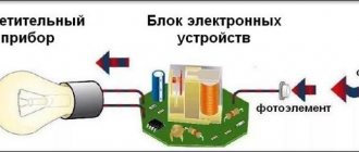
Excessive energy costs make you think about possible ways to save. Using a light sensor, you can create the optimal level of lighting for your home and surrounding area without significant financial investment. Such devices have a well-thought-out design, ensuring timely switching on or off of the lighting system when darkness falls. They are divided into types. Having understood what it is and why such a device is needed, you can optimize the size of the invoices issued by the management organization.
Device
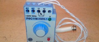
The device for automatically turning on the light includes a photo relay that ensures its operation under certain conditions. Photo relay includes:
- A housing designed to accommodate the remaining elements and correctly fix them relative to each other. For this purpose, special holes or other elements are provided in the housing to ensure reliable fixation;
- A photocell, which is a light-sensitive current sensor. From it, control pulses are supplied to the control element. The device may include a phototriac, phototransistor, LED, photothyristor;
- An electronic unit that includes a power source, an electromechanical relay, and a signal amplification device.
If light sensors are connected to devices with high power during operation, it includes a repeater of electromechanical relay contacts. Some models have the ability to adjust the response time. This allows you to prevent false alarms in the dark, for example, when accidentally hit by car headlights or other sources.
Possible connection diagrams for photo relays for street lighting
Schemes for including a photo relay in an outdoor lighting system depend on the technical characteristics of the device (operating voltage) and the presence of other additional features that were described above. The simplest connection option when using devices with an operating voltage of 220 Volts is shown in the following figure. The simplest scheme for including a photo relay in an external lighting control circuit. In this case, connecting the device to the lighting control circuit is carried out in a junction box by connecting the electromechanical relay contacts to the phase wire going to the controlled light source. The neutral wire goes to the lamp directly from the junction box. When using a motion sensor in a lighting control circuit, it is installed in the phase wire after the photo relay; the connection diagram in this case is shown in the figure. Inclusion of light and motion sensors in the control circuit When installing a photo relay in the control circuits of a contactor or magnetic starter, the connection diagram is as follows.
How does it work
As soon as the illumination level decreases to a predetermined level, the photocell contacts close and the daylight sensor turns on the system. As the amount of natural light increases and the user-set level is reached, the contacts open and the system turns off.
The order of operation of the device and its capabilities largely depend on the design. The functionality of most modern devices is not limited to triggering at a certain level of light.
Light sensor circuit using a photoresistor and relay
Examples of sketches for working with relays are given in the article on programming relays in Arduino. In this case, we do not need to make complex movements: after determining the “darkness,” we simply turn on the relay and apply the corresponding value to its pin.
#define PIN_RELAY 10 #define PIN_PHOTO_SENSOR A0 void setup() { pinMode(PIN_RELAY, OUTPUT); digitalWrite(PIN_RELAY, HIGH); } void loop() { int val = analogRead(PIN_PHOTO_SENSOR); if (val < 300) { // Light, turn off the relay digitalWrite(PIN_RELAY, HIGH); } else { // It's a little dark, turn on the light digitalWrite(PIN_RELAY, LOW); } }
Main types
Light sensors can be interfaced with other automation devices. This significantly expands the functionality of the models and makes them more popular among consumers. Devices with:
- Timer. Such models allow you not only to adjust the level of illumination at which they operate, but also to set a time frame. In this case, the photo relay will operate in the time interval set by the user;
- Motion sensor. The best option for optimizing costs. Such devices are installed near pedestrian paths and in local areas where people periodically move or vehicles move. The daylight sensor is triggered if a large object is in the coverage area. As a result, at night, the location of the device will always be dark, but as soon as a car enters the site or a bird flies in, the device will work and the lighting will turn on;
- Programmable settings. Such devices have the most sophisticated technical equipment. They allow you to configure the operating mode at different time intervals. It is possible to regulate not only within a day, but also within weeks, months or a specific season. They also trigger when there is movement in the selected area.
Depending on the version, sensors can be:
- Infrared. The device is triggered when an object heated to a certain temperature enters the coverage area. They are equipped with infrared detectors. During operation, difficulties may arise if there is a pet within the device's coverage area; Acoustic. Such devices respond to sound. To turn on the device, a loud sound or creaking sound must be heard;
- Microwave. The devices are active type sensors. During operation, they generate waves in a certain microwave range and then receive them back. If there is a difference, the circuit is closed/opened and the device is subsequently turned on/off;
- Ultrasonic. According to the principle of their operation, they are comparable to microwave-type models. However, when choosing this option, you should remember that they can have some effect on pets; the presence of ultrasound can affect their behavior;
- Combined. Some models respond to several influencing factors at once. In terms of reliability, they are significantly superior to all the varieties listed above, but at the same time they are much more expensive.
New generation relays include astronomical sensors. They allow you to control the operation of lighting fixtures, but they work on a different principle. Such devices include a microcomputer that allows you to configure the operation of the device depending on its installation location. When setting up the device, GPS data for a specific locality is entered. Such devices automatically determine when the lighting lamps are turned on. This completely eliminates the possibility of false alarms typical of photocells. In addition, they are able to remain operational in any weather.
What does the sensor consist of?
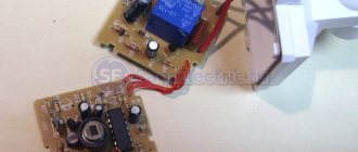
When purchasing a photo relay, the client receives at his disposal a box containing all the components of such a photo relay. Its elements are:
- photosensitive component;
- a switch that responds to twilight;
- interval relay;
- sensitivity relay.
Some photo relays may use multiple light-sensitive elements to provide a more accurate estimate of the quantity and quality of incoming light. They are able to determine the wavelength that affects the photosensor. This is necessary so that the photo relay does not respond to lighting from a flashlight, but only to sunlight. In some photo relay models, additional trimming resistors are installed, which make it possible to set the interval during which the lighting will be turned on in time, as well as after what period after sunset the power from the photo relay will be supplied.
The end consumers that will be used in conjunction with photo relays can be not only ordinary incandescent lamps. These can be LED strips, as well as gas-discharge lamps. A photo relay can power any number of them if connected correctly. Some photo relays have a built-in signal amplifier, which is fed to third devices that control the lighting system. To ensure that the switching process occurs as reliably as possible, thyristor switches can be installed in the photo relay, which transmit the signal from the photo relay as quickly as possible.
Advantages and disadvantages
Lighting sensors attract consumers with the opportunity to save energy. The advantages of using photocells include:
- Low current operation;
- Prompt operation. The device turns on and off almost instantly;
- High performance;
- Long service life.
When choosing a device like this, you should take into account that they do not work well in extreme conditions. At the same time, they place increased demands on the tightness of the housing. If moisture gets inside the device, there is a high probability that the sensor will fail and the sensor will not work due to oxidation of the contacts.
The device will not function properly if a layer of dirt and dust forms on its surface. That is why during operation it is necessary to constantly clean the devices.
Microwave motion sensors
Sensors of this type are active; the emitter emits electromagnetic waves with a frequency of 5.8 GHz. Due to the minimum wavelength, the device is highly sensitive and accurate.
There are no barriers to microwave waves in the form of walls or furniture. This should be taken into account when designing. Microwave sensors are most often installed in non-residential premises that require enhanced security, for example, in museums, bank vaults, places where weapons or important documents are stored. In an apartment or private house, it is appropriate to install a microwave sensor in a separate non-residential premises that requires security.
Specifications
Light sensors for street lighting have technical characteristics that determine the possibility of their operation in certain conditions. For a photo relay, these parameters are:
- Supply voltage. 220 V models are installed in the apartment. If the installed system includes 12–36 V devices, a low-order circuit must be provided. This voltage is necessary to start the contactors of magnetic starters;
- Maximum permissible current. It is important when connecting devices operating from 220 V. In this case, an electric current passes through the contacts of the photo relay, intended to ensure the operation of the light source;
- The temperature at which the device can be operated. Outdoor models must remain operational over a wide temperature range. They must cope with the task in frost and extreme heat;
- Degree of protection. The outdoor device must have sufficient protection against moisture and water;
- Dimensions and weight. They are of fundamental importance when space is limited at the installation site.
What to choose
Choosing a photo relay for lighting is based on specific needs or a project. To do this, several factors must be taken into account:
- total lighting power;
- position of the area for lighting;
- lighting voltage;
- sensor installation location;
- lighting operating hours;
- presence of a surveillance system;
- the need for additional modules.
Next to each item on this list you must make the required notes. This will allow you to quickly analyze the characteristics of the photo relays discussed above. In some cases, it will be necessary to install several light sensors.
Selecting a location
How effective the light sensor will be for turning on the light largely depends on its location. The box can be located inside or outside the house, depending on the purpose of the selected model.
When choosing a location for installing the device, you need to consider:
- Illumination. When choosing a location, you should avoid areas exposed to artificial light. If the area is located in close proximity to windows, streetlights, and is often illuminated by car headlights, it should be abandoned. At the same time, there should be no obstacles to the passage of natural light. Otherwise, the sensor will not work correctly;
- Reliability of fastening. The base on which the device is fixed must be able to support its weight. The fastening itself should not come into contact with components that do not have sufficient strength and reliability;
- Availability. During operation of the device, it may be necessary to monitor the condition. In addition, the selected site should allow for reliable fixation of the device. When choosing a location, preference is most often given to sites located at a height of 1.8–2 m. This height will allow for smooth installation and will not create difficulties during maintenance or cleaning. If the device is placed higher, a ladder will be required for installation and maintenance.
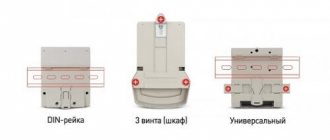
Installation work
The daylight sensor is installed according to the specific manufacturer's recommendations. A detailed algorithm of actions is described in the instructions supplied with the model.
The connection process usually does not cause serious difficulties. Many people install a light sensor in their home with their own hands. To install, you need to carefully inspect the device.
Each model will have three wires at the input: power, neutral, phase. Their colors may differ depending on the manufacturing company, but there will definitely be red, which is where the phase comes out. It is designed to connect the load.
Brown is used for power connection. Some manufacturers make it black. Zero is colored blue or green. The connection of the wires must be made in a special sealed distribution block.
If you plan to connect one device, the distribution block is located in close proximity to the relay. However, before you begin installation work, you should carefully read the recommendations of the manufacturer of the selected model. This will allow you to more accurately determine the location of all elements and the order of their installation.
In order to reduce energy costs, a daylight sensor is most often chosen with a motion sensor. In this case, the red wire is used to connect the motion sensor and the lamp. The remaining two are used to connect phase and zero. The connection procedure is described in more detail in the instructions for each model.
In the most general case, the work is performed in the following sequence:
- The power goes out. The shutdown procedure depends on the location of the work. Every owner must know how to do this in order to turn off the power to a house or apartment in case of an emergency;
- The photo relay is connected to the power wire;
- The ends of the wires are stripped. The length of the stripping should allow easy connection to the terminals;
- A hole is selected in the housing to connect the photo relay. If there is none, it is formed using a tool with a suitable cross-sectional size;
- All housing openings are sealed. This will prevent dirt, dust and moisture from getting inside. As a result, the installed daylight sensor will last much longer and will not create problems during operation;
- The device is connected in accordance with the recommendation src=»https://osensorax.ru/wp-content/uploads/2020/07/13-datchik-sveta-13.jpg» class=»aligncenter» width=»600″ height= "526"[/img]
- Wires are being prepared with which lighting fixtures will be connected to the device. The wires are cut to size, the ends are stripped, and they are connected to the required terminals according to the instructions supplied with the device;
- The photo relay is manually configured;
- The housing cover closes. Electric current is supplied to the device. The sensor is being tested.
During the installation process, the device often has to be moved, choosing a suitable spatial arrangement. In order not to waste time constantly unscrewing and tightening, you should not immediately fix the device “tightly”. This can be done once the final location has been selected.
The connection diagram may differ slightly. Each manufacturer tries to offer its own device that would turn on the light as dusk falls. In order not to encounter obvious difficulties, it is worth familiarizing yourself with the connection procedure before purchasing and assessing the possibility of using it at home. To perform installation work you do not need to have any special skills. However, during the installation process it is necessary to follow safety rules.
Typical problems and errors
When installing photo sensors, a beginner, especially one who does not have the relevant experience, often makes common mistakes.
Indoor setup
Sometimes, for convenience, threshold adjustment is performed indoors, which should not be done.
The fact is that the sensitive element inside the housing (or external) reacts not only to visible light, but can also perceive solar ultraviolet radiation. Its absence during indoor testing will affect the “accuracy” of the response: home glazing extinguishes up to 80% of the UV spectrum.
Wire connection errors
Photo sensors are usually connected to street lighting using a three-wire circuit: phase, neutral, load.
Sometimes there is confusion with the purpose of the conductors - what to connect where. To understand how to connect the wires correctly, you can use the color coding of the wires as a guide. One of them is usually green or blue - this is how “zero” is indicated.
The remaining pair of wires also has its own color - for example, red, brown.
In the case in the picture above, the brown wire is the input from the electrical feeder, and the red wire leads to the light bulb. In it, the phase occurs when the photoswitch is activated.
Installation location
It is important to choose the correct installation location. Correct and incorrect installation of photo relays for street lighting using examples:
Correct and incorrect installation of photo relays for street lighting using examples:
In most cases, to comply with this rule, photo relays are placed above the lantern, or even on its body, if technically possible.
If an error is made in the installation, this will lead to spontaneous false alarms, periodic “blinking” of the light and other errors.
It may happen that it is impossible to “hide” the photo sensor. Then you should separate it from the lantern with a thick, opaque partition.
Performance deterioration
Over time, relays sometimes begin to work worse. This occurs due to natural degradation and contamination of the material: the photocell cap darkens and transmits sunlight less well. Dirt can be removed by simple wet cleaning, but degraded plastic must be replaced - separately, if possible, or together with the entire device.
Device position
It is important not only how to connect the light sensor to the load and network, but also in what position in space to install the device. Some types of devices can only be placed “upside down”, with the photocell facing down
To determine the correct position, the following marks are applied to the body:
Incorrect installation will result in malfunction or moisture ingress if the “bottom” of the protective cover contains unprotected process holes.
Connection and subsequent configuration of the sensor
Most modern devices allow you to select the sensitivity of the device and determine the response threshold. As a rule, light sensor manufacturers place the adjustment at the bottom of the relay.
Adjusting the photosensitivity light sensor is carried out in the dark. Wait for the time when the device should start working in order to connect artificial lighting. Having found a disk that regulates the light on the bottom of the sensor, they begin to turn it, making the device work.
Most often, the manufacturer indicates a minus sign on the body, then rotating in a given direction reduces the sensitivity of the sensor. The device will only operate in complete darkness. If this option is not suitable, the disk should be rotated in the opposite direction. This will improve sensitivity.
In addition to adjusting the photo relay itself, you should configure the devices associated with it. In this case, the entire system will work properly.
Basic parameters of motion sensors
- Two-pole or three-pole. Simple two-pole sensors can only be connected in series to incandescent lamps; three-pole sensors can be connected to lamps of any kind.
- The operating area or range is usually from 3 to 12 meters.
- The detection angle in the horizontal plane varies from 60 to 360 degrees in different models. In the vertical plane, the detection angle is smaller - 15-20 degrees.
- Rated power connected to the sensor. If the total load exceeds the sensor capacity, you need to install an intermediate relay or increase the number of sensors.
- The sensor switch-off delay is programmed so that a person has time to walk through the entire illuminated area, even leaving the coverage area of the device. The time can be set from 5 seconds to 10-12 minutes.
How to connect to a spotlight
Another issue that requires consideration is how to properly connect a motion sensor to a floodlight.
To do this, you can use one of the following schemes:
- WITH THREE CONTACTS. In this case, the phase is supplied from the shield to terminal L. From output A, the wire goes to the input L of the spotlight. Voltage is supplied when the motion sensor is triggered. Contacts N are combined and directed to the shield. The ground is sent directly to the spotlight and connected to the PE to remove possible voltage from the metal housing.
- USING A SINGLE KEY SWITCH. In the solution discussed above, the use of a switch is not provided. But this can be fixed. As a rule, the switch is mounted in a phase break (before the product that controls the movement). In this case, when the switch is turned off, the voltage is removed from the entire circuit. The second option for connecting the switch is parallel to the phase and the output of the motion sensor. With this solution, you can turn on the lighting without being tied to other devices. When the switch is turned off, the entire circuit operates as usual.
- USING A TWO-KEY SWITCH. In this case, a certain symbiosis of the two circuit solutions discussed above is introduced. One contact of the switch breaks the phase, and the second comes in parallel. When both buttons are disconnected, the voltage is completely removed from the circuit. When the first key is turned off, the sensor operates in normal mode and turns on the spotlight when movement occurs. If only the second key is activated, voltage is immediately applied to the lamp.
- TWO SENSORS. The same principle applies here as discussed above. Two movement-controlling organs are arranged in parallel, after which they are connected to the power circuit and the spotlight.
- CONNECTING THE LAMP TO A LOWER VOLTAGE. If it is necessary to turn on the spotlight at a lower voltage (12, 24 or 36), a power supply is installed in front of the input, reducing 220 V to the required level. In this case, three wires (with ground) are supplied to the power supply input; only power is sent to the sensor.
- FOR A SEPARATE PHOTO RELAY. When installing old motion controllers without a photo relay, the latter must be connected separately. In this case, the wire goes from the output of the sensor to the relay, and after that to the input of the spotlight. The zeros are combined and the ground goes towards the light source.
Above are the basic diagrams that allow you to connect a spotlight with or without a switch. Here everyone makes a decision taking into account the current tasks and characteristics of the room.