What is PWM?
PWM (pulse-width modulation, English pulse-width modulation (PWM)) is a method of controlling power by pulsed power supply. The power varies depending on the duration of the applied pulses.
PWM is used everywhere in modern electronics, to adjust the brightness of the backlight of your smartphone, the speed of rotation of the cooler in the computer, to control the motors of a quadcopter or hoverboard. The list can be continued endlessly.
In hobby electronics, PWM controllers are often used to control the brightness of LED strips and to control powerful DC motors.
Happy Birthday to radiokot.ru and the Main Cat! And also moderators and everyone who helps the site become better and more interesting. I wish you all the best! Keep it up! Personally, I celebrated the Cat’s birthday, as in the picture, which I advise everyone to do.
“In order to clearly understand a process, you need to hear about it a hundred times, or just see it once.”
Nowadays, the whole world revolves around pulse width modulation (PWM), and needless to say, even day and night are subject to PWM (in winter, the day is shorter than the night and vice versa J). PWM is now used wherever one can imagine its use: regulators, stabilizers, converters, power supplies and other devices. Taking into account the trend of increasing power, the steady increase in the used frequencies in power and converter technology, as well as a decrease in weight and dimensions, I decided that it is simply necessary for everyone to have a wide-range PWM generator in their home laboratory. But this, of course, should not be just a generator. It is necessary that it have frequency adjustment over a wide range, duty cycle regulators, DEAD TIME regulators, single-cycle and push-pull outputs, as well as output inversion for each. Inversion of the outputs is necessary to test the bridge converter. And you never know what else you might want to explore. But at the same time, it should be easy to assemble, adjust and repeat. In this case, it will be enough to cover the frequency range in single-cycle mode from 60 kHz to 2 MHz, in push-pull mode from 30 kHz to 1 MHz. Adjust the duty cycle in single-cycle mode from 1% to 99%, and in push-pull mode from 2% to 98%, with the ability to adjust the DEAD TIME pause. The generator must have a minimum number of range switches. Everything should be adjusted smoothly and without jumps. It is advisable to have coarse and fine settings for each control parameter.
Using such a generator, you can check the quality of operation of field-effect transistor control drivers, the speed performance of various components, and much, much more.
In order not to bore you with reading the entire article, I will immediately show you what kind of signal was obtained at the outputs in different modes and at different frequencies:
Using this generator, I start any power supply in which the microcircuit does not give impulses to start, or goes into protection for some unknown reason. Smoothly increasing the duty cycle, I look at what is happening at the output of the block, or the current shunt of the key transistor. Finding a fault in any pulse units with this generator is just a fairy tale and takes only a few minutes. For example, I remove the gate of the power transistor from the original microcircuit and connect it to my generator with a driver. In order to connect, for example, on the high side to push-pull devices, sometimes this is necessary, you need to use an optodriver on a 6N137 or any other fast optocouplers.
You can also check what operational and audio amplifiers are good for. Since only voltage repeaters have the lowest distortions, I will perform the test in this mode. I will give an example of testing the most common operational amplifier type LM358. This will shock some audiophiles. So, I categorically do not recommend using the LM358 in even low-class audio amplifiers.
Just for fun, I take the very first Soviet opamp, K140UD1B, and put it to the test. Its performance is significantly better than that of the LM358.
You can check the delay time in logic gates and the minimum pulse width for flip-flops.
I even checked how the zener diode TL431 would behave at a frequency of 1.3 MHz:
Yellow is the entrance, blue is the exit.
And also experience and check much more…….
Here, in a nutshell, are the capabilities of my generator.
When I set myself a task, I tried to google and find a ready-made solution. The search was unsuccessful. As a result, it was decided to create a circuit that would meet the needs. Now I will introduce you to the results of my research that lasted about a year
My research
Study one: on a ready-made PWM regulator.
At first glance, the most attractive and simple circuit found in datasheets and the Internet seemed to be a circuit based on a ready-made PULSE WIDTH MODULATION controller of the TL494 type and its analogues KA7500. TL 494 and its subsequent versions are the most commonly used microcircuit for building push-pull power converters.
But in fact, this solution suits our tasks only to 1/10 of the solution and it cannot be used at frequencies above 100 kHz - in single-cycle mode and up to 50 kHz - in push-pull mode. Why? Although according to the datasheet it can be used up to 300 kHz, I did not like how it behaves at frequencies above 100 kHz.
What the datasheet says:
Allowable operating frequencies are from 1 to 300 kHz, the recommended range is Rt = 1...500 kOhm, Ct = 470pF...10 µF. In this case, the typical temperature drift of frequency without taking into account the drift of attached components is +/-3%, and the frequency drift depending on the supply voltage is within 0.1% over the entire permissible range. But the point is not the frequency drift, but the inconstancy of the fill factor regulation depending on the frequency.
I tried to test its capabilities, and wanted to cover the 2 MHz range I needed, but at frequencies above 1 MHz it did not start normally. I had to limit myself to only 1 MHz for now. I made five frequency control ranges, installed a voltage stabilizer at 12 volts for the power supply with blocking capacitors so that the purity of the experiment would not be disturbed, and began testing.
Scheme:
Experimental circuit development board:
Jumpers for frequency selection:
The results of the testing of the TL494 capabilities:
This microcircuit is not suitable for my requirement for a generator, and no means or tricks to overclock it to a higher frequency led to anything. The limit of dreams with it is 100 kHz (with a stretch of 150 kHz). At a higher frequency, the very slow comparator used in the crystal circuit makes itself felt. The built-in correction also interferes with increasing the frequency. We read from the datasheet the features of this microcircuit:
For stable operation of the trigger, the switching time of the digital part of the TL494 is 200 ns. At clock frequencies up to 150 kHz with zero control voltage, the resting phase = 3% of the period (equivalent bias of the control signal 100..120 mV), at high frequencies the built-in correction expands the resting phase to 200..300 ns. Since it has very slow error amplifiers (in fact, operational amplifiers with Ku = 70..95 dB at DC voltage, Ku = 1 at 300 kHz), I do not use them in the test circuit at all, and they are blocked. These amplifiers are not designed to operate within one clock cycle of the operating frequency. With a signal propagation delay inside the amplifier of 400 ns, they are too slow for this, and the trigger control logic does not allow it (side pulses would appear at the output). In real voltage converter circuits, the cutoff frequency of the feedback circuit is selected on the order of 2 - 10 kHz.
Notes on the operation of the 494 chip at higher frequencies that do not suit me:
1. The built-in sawtooth voltage generator short-circuits the capacitor for a long time, as a result of which a platform with zero potential appears before a new charge cycle.
Oscillograms of generator operation at different frequencies:
2. Strong dependence of the duty cycle on frequency, which manifests itself with an increasing effect after passing a frequency of 100 kHz.
Considering the oscillograms of the operation of a PWM regulator with TL494 at different frequencies, with maximum and minimum duty cycle, changes in the minimum and maximum duty cycle depending on the frequency are clearly visible.
As you can see, the change in the minimum duty cycle at a frequency of 50 kHz = 5% and at a frequency of 1 MHz = 14.3% differ by almost three times. But the change in the maximum duty cycle is generally surprising: at a frequency of 50 kHz = 93% and at a frequency of 1 MHz = 60.7% they differ by 32%!!!
That's why I put this simple and convenient scheme aside. It will be useful to me in the future: I will still return to it, but this time on discrete fast comparators and normal fast triggers.
Study two: on a 555 timer.
Further along the way I had a circuit based on an NE555 timer, which I used only as a sawtooth voltage generator. I didn't realize that it would also be quite slow, but still a little better than the previous TL494. With it you can go up to frequencies of about 200 kHz in single-cycle mode. You just need to add a comparator and a trigger with OR-NOT logic.
Oscillator circuit based on a 555 timer:
Oscillograms of the operation of a sawtooth voltage generator on a 555 timer at frequencies of 332 kHz and 462 kHz.
Here you can see the rounding of the peaks and decline of the impulse. At frequencies above 500 kHz the saw becomes unrecognizable.
Disillusioned with ready-made solutions based only on analog elements, I tried to synthesize PWM purely on digital logic elements and counters with triggers, without using analog components, but other, much more complex problems lay in wait for me there. Alignment of signal propagation delays across elements, etc. A particularly big problem is caused by triggers and counters, which do not want to click at all at short pulse durations and simply stupidly skip counting. This means that the keys that the generator will work on will very soon come to an end. I abandoned this idea after a week of fighting with 561 logic. It turns out that it is very slow for such frequencies - 20 MHz when dividing the PWM by 10%. After another two weeks, I refused 1533 too.
The final circuit of the generator.
After several unsuccessful attempts to make my dream come true (to have a generator with a 2 MHz PWM in my home laboratory), I rested for a week or two, thought, gained strength, and again began solving the problem. This time without tricks and easy ways, taking into account previous developments and mistakes. Of all the solutions tested, the TL494 or timer circuit provided the greatest ease of use. Therefore, it was decided to clone the NE555 and TL494 hardware using high-speed components and assemble a kind of “symbiosis” of the two microcircuits using separate comparators and logic. I took the comparators with TTL output that were in my desk - KR597CA2, but any others are also possible, most importantly fast-acting and with TTL output. Well, if you suddenly want to go wild, then ESL will be much cooler (then 20 MHz is not the limit), but I don’t need such a high frequency yet (except for a converter with inductance without a ferrite core). Then you need to install KR597CA1, and K500 series logic.
After the first launch of the scheme, many incidents were discovered, but as debugging progressed, many of the problems were removed, and the scheme worked like clockwork.
Scheme:
The circuit consists of a sawtooth voltage generator (consisting of a current stabilizer on transistors VT1, VT2, VT3; two comparators DA1, DA2; trigger DD1 and discharge transistor VT4), a circuit for separating rectangular pulses (with a width depending on the threshold voltage on DA3), two stabilizers reference voltage (2.5V and 2.9V), push-pull signal former (on trigger DD2 and elements DD3 DD4 2-OR-NOT), repeater and inverter for single-cycle output (on DD5, DD6).
Photo of the breadboard:
To make the setup process easier, I will provide voltage oscillograms at each important point in the circuit. So…
Ramp voltage generator. The capacitor is charged through a current stabilizer. Channel 1 – voltage at capacitor C5, channel 2 – voltage at the base of discharge transistor VT4.
The graphs show an inexplicable fact that the voltage moves into the region of negative values, but this does not interfere with the work, since later I will also introduce a small negative bias into the circuit for separating rectangular pulses into the set voltage using a divider R6, R10 to cover the entire range of voltage changes of the “saw” . R1 is selected to limit the upper maximum frequency (I limited myself to only 2 MHz, although the whole circuit works fine up to 5 MHz).
Voltage oscillograms at the outputs of comparators DA1, DA2 at different frequencies. Channel 1 – voltage on the comparator DA1 pin 14, channel 2 – voltage on the comparator DA2 pin 14:
To combat the “ringing” of the comparator near the switching zone, in the circuit for isolating rectangular pulses on DA3, I introduced POS (positive feedback) resistors R16, R15 at the same inputs and outputs of the comparator. PIC is needed at frequencies below 1 MHz. At a frequency of 2 MHz, this circuit is not required and ceases to participate in the operation itself, as can be seen from the oscillograms. Voltage oscillograms at the inputs of the DA3 comparator at different frequencies. Channel 2 – voltage on the comparator DA3, pin 2 – setting the switching threshold, channel 1 – voltage on the comparator DA3, pin 3 from the “saw” generator. Oscillogram at a frequency of 96 kHz. Channel 2 enlarged. A wavy line is visible synchronously with the switching of the comparator - this is the work of the PIC to set the hysteresis. The depth of hysteresis could be reduced, but the keys that will be controlled by the generator are at stake, so we will leave everything unchanged.
Next is a circuit for selecting rectangular pulses with a width depending on the threshold voltage on DA3. A sawtooth voltage is supplied to the direct input of the comparator, and a voltage to set the comparator switching threshold is supplied to the inverse input. The output is a rectangular pulse. We look at the oscillograms, understand and delve into it.
Everything is clear here. Only if you need a push-pull output for work, then you should not get carried away with a very small (99%) duty cycle. Since the trigger does not have time to switch at a short duration of the input pulse, and will simply skip periods, producing two identical, single-cycle pulses at the output instead of push-pull pulses in turn, and this is fraught with bad consequences, such as through breakdown of simultaneously open keys.
Next I will show how the trigger switches when the pulse duration is sufficient for it to operate normally at different input frequencies. The output frequency of a D flip-flop is half the input frequency, and always has a duty cycle of 50% regardless of the input duty cycle. All this can be seen in the graphs below.
And this is how a trigger behaves when input pulses are of insufficient duration:
You can see how the scan gets lost and the same missed pulse is visible. And this leads, for example, in a half-bridge converter to an end-to-end “kototok”.
Next, I will show how half a cycle of a push-pull pulse is formed, passing through a comparator, a trigger and a 2OR-NOT logic element:
I placed what happened on the output contacts in the first picture. We look carefully and study. As can be seen from the graphs, the minimum pulse duration at the push-pull output is increased to 5% in order for the trigger to switch clearly at an input frequency of 2 MHz. At frequencies up to 500 kHz it can be set to 1% without fear of missing pulses.
The main nuance for setting up the generator: the most important thing is that there should be blocking ceramic capacitors of the KM-5 type, 0.1 μF minimum, or imported SMD, on each microcircuit body. Without them, the circuit works very unstable. One side of the board is used for tracks, and the other is used as a screen; it must be connected to the case at several points.
The power supply does not have any special features. For the +12v channel, Krenka or 7812 is used, and for the 6v channel, 7906 is used
I’ll write about 2 MHz output drivers later, otherwise there’s a lot to read. You can use ready-made driver chips or assemble them using discrete elements.
Thank you for your attention, and for your patience, and for having the strength to read to this line.
I also congratulate you and wish you a lot of valerian!!!
Breadboard in Layout 5, video of the generator in different modes and pictures separately in files.
Files:
board image archive video
All questions in the Forum.
PWM operating principle
Unlike linear systems, where power is regulated by reducing electrical parameters (current or voltage), when using PWM, the power transmitted to the consumer is regulated by the pulse time, which significantly increases the efficiency of the controller. In analog systems, the residual power was dissipated in the form of heat; here, when consumption is reduced, the residual power is simply not used.
The main characteristic of PWM is DUTY DUTY (percentage of filling) - the percentage ratio of the pulse duration to the period. The figure below shows 5 duty cycles of a rectangular PWM signal:
PWM duty cycle
PERIOD is the time during which a full cycle of signal oscillation occurs. Measured in seconds. It depends linearly on the signal frequency and is calculated by the formula:
T(period) = 1/f(frequency)
f(frequency) = 1/ T(period)
The PWM frequency is the number of periods (or, if you prefer, oscillation cycles) per unit of time. Frequency is measured in Hertz (Hz), 1 Hz is one oscillation every 1 second.
If the signal makes 100 oscillations per second, then the frequency is 100 Hz. The higher the frequency, the shorter the period.
PWM generator on op-amp
The initial data for the calculation are presented in Table 34.
Table 34. Initial data for calculation
| Entrance | Exit | Nutrition | ||||
| ViMin | ViMax | VoMin | VoMax | Vcc | Vee | Vref |
| -2.0 V | 2.0 V | 0 V | 5 V | 5 V | 0 V | 2.5 V |
Description of the scheme
This circuit uses a triangular pulse generator and a comparator to generate a PWM signal with a frequency of 500 kHz and a duty cycle inversely proportional to the input voltage (Figure 42). The operational amplifier (U3) and comparator (U4) generate a triangle signal that is fed to the inverting input of the second comparator (U2). The input voltage of the circuit is supplied to the inverting input of the error amplifier (U1) and then to the non-inverting input of the comparator (U2). The output PWM signal is generated by comparing the input voltage and the triangle signal. The signal from the output U2 is used for feedback and is fed to the input of the error amplifier (U1). This is done to improve the accuracy and linearity when generating a PWM signal.
Rice. 42. PWM generator circuit
We recommend that you pay attention to:
- use a comparator with a push-pull output and minimal delay time;
- Use an op amp with suitable slew rate, GBW and output voltage range;
- the frequency of the pole created by capacitor C must lie below the switching frequency and significantly above the audible audio range;
- The impedance of the reference voltage source should be kept to a minimum. The output of an op-amp can be used for this purpose.
Calculation procedure
- We select the gain for the input signal using formula 1:
- We select resistances R1 and R2 to divide the reference voltage and obtain unity signal gain at the non-inverting input (formula 2):
Then VO_DC = 2.5 V.
- The amplitude of Vtri should be selected higher than the maximum amplitude of the input voltage (2.0 V) to avoid 0% and 100% duty cycle of the PWM signal. Select Vtri = 2.1 V. Amplitude V1 = 2.5 V (formula 3):
Set R6 = 10 kOhm and determine R5 using formula 4:
- We set the PWM frequency to 500 kHz, based on formula 5:
We set C3 = 100 pF and calculate R7 using formula 6:
- Select C1 to limit the amplifier bandwidth below the PWM frequency (formula 7):
- We select C2 to filter the noise Vref and substitute it into formula 8:
C2 = 100 nF (nominal).
Circuit Simulation
Simulation in constant current mode (DC analysis) is shown in Figure 43.
Rice. 43. Dependence of the amplifier output voltage on the input
The oscillogram of transient processes is presented in Figure 44.
Rice. 44. Oscillograms of transient processes
Recommendations
The parameters of the op-amp used in the calculation are given in Table 35.
Table 35. Parameters of the op-amp used in the calculation
| OPA2365 | |
| Vss | 2.2…5.5 V |
| VinCM | Rail-to-rail |
| Vout | Rail-to-rail |
| Vos | 100 µV |
| Iq | 4.6 mA |
| Ib | 2 pA |
| UGBW | 50 MHz |
| S.R. | 25 V/µs |
| Number of channels | 2 |
Alternatively, op-amps can be used, the parameters of which are presented in Table 36
Table 36. Parameters of alternative op-amps
| TLV3502 | OPA2353 | |
| Vss | 2.2…5.5 V | 2.7…5.5 V |
| VinCM | Rail-to-rail | Rail-to-rail |
| Vout | Rail-to-rail | Rail-to-rail |
| Vos | 1 mV | 3 µV |
| Iq | 3.2 mA | 5.2 mA |
| Ib | 2 pA | 0.5 pA |
| UGBW | – | 44 MHz |
| S.R. | – | 22 V/µs |
| Number of channels | 2 | 2 |
How to connect to the load
The PWM signal generator should not be connected directly to the load, because it is low-current and will most likely burn everything out immediately. In order to control the load, you need a switch on a mosfet transistor. We take an N-channel mosfet transistor IRF3205 and assemble everything according to the diagram:
Arduino PWM on IRF3205
Resistor R1 is needed to protect the Arduino pin from burnout, and resistor R2 is needed to ensure that the transistor is completely closed when the Arduino does not provide an output signal.
As you can see, nothing complicated. Four elements and the PWM controller is ready. He can already control a single-color LED strip or some kind of motor.
If you need a three-color ribbon or more ribbons (we make multi-channel PWM), simply add keys to pins D3, D5, D6, D9, D10, D11 ( only PWM works on them ). In total, Arduino is capable of controlling the power of 6 devices simultaneously.
The IRF3205 is capable of withstanding currents of up to 70 Amps at voltages of up to 55 Volts; such characteristics are quite sufficient to solve most household problems.
Controller Circuit Improvement
Of course, there are always ways to further improve the scheme:
- It would be nice to provide some buffer on a transistor or a simple amplifier operating in class AB between the PWM output and the microcontroller. In this case, it will protect the microcontroller from damage and additionally boost the signal.
- Additional frequency control steps would also be helpful. If you are going to implement the project, we suggest a larger microcontroller with hardware PWM for SMPS, so that there are 2/4 channels and idle time regulation.
It is also possible to expand the filling control range to 0..100%. This can be useful when testing the operation of PWM control units. For example, at 100% filling - measuring the voltage drop across the tracks and the open key.
If you need to control the positive contact
In this case, we will need another mosfet transistor - P-channel. The circuit is similar, only the pull-up resistor is connected to the positive.
You will also need to invert the signal at the Arduino output, because when 5 volts are applied, the transistor will close, and when 0 volts is applied, it will open, which means that a PWM with a duty cycle of 30% will produce 70% power at the output of the circuit.
PWM on irf4905, power supply 5 v
It is worth making a reservation that such a circuit will only work with a power supply no higher than 5 volts , since in order to completely close the P-channel transistor it is necessary to pull its gate to the power positive, and the arduino is capable of delivering only 5 volts to the digital pin. This means that when powered at least slightly higher than the voltage supplied to the digital pin, the transistor will not completely close at the top of the PWM pulse and WILL HEAT VERY HEATED. It will also not be able to completely turn off the load.
If you need to control, for example, a 12-volt device, then the circuit will become a little more complicated. A so-called “swing arm” or field-effect transistor driver will be added. According to the classics, it is assembled on two and sometimes three transistors, but we have a slightly simpler option that works at low frequencies:
Arduino, PWM control via positive wire IRF4905
PWM signal generator on a microcontroller with adjustable duty cycle
This is a simple PWM generator operating from a stabilized power source with a voltage of 4.75...5.25 V. Its output generates a rectangular signal with a constant frequency of 1 Hz, but with an adjustable duty cycle in the range 0...100% in steps of 1%, in depending on the installed jumpers J1-J7.
The device will find application in the workshop of every radio amateur, for example, when testing various prototypes of digital circuits.
The generator is based on the popular ATmega48 microcontroller. Instead, you can use the ATmega88 or ATmega168 models, which differ only in the larger amount of memory.
The control program is written in assembler and is identical for each of the mentioned microcontrollers (occupies 2440 bytes of flash memory). After turning on the power supply or resetting the microcontroller using the S1 button, the control program configures pin PB0 (#14) as a low logic level (LOW) output and all other pins as logic high inputs (internal pull-up resistors enabled).
Then the microcontroller reads the state of jumpers J1-J7, which are connected to pins PD0...PD6. If all jumpers are open (OFF), the program proceeds to execute a loop that generates a signal with 0% duty cycle (mode 0) and the generator output is still in a low logic state (LOW).
However, if a certain binary value X = 1...99 is set using jumpers (J1 is the least significant bit), then the program moves to the corresponding cycle (mode X), which is executed without interruption.
In each such cycle there are two instructions that switch the state of the PB0 output to the opposite. The time between switches varies (except for 50% fill), but their sum is always 1 second. Thanks to this, the output of the generator produces a rectangular signal with different filling, but always with a frequency of 1 Hz.
If the jumpers are set to a binary value of X > 99, the program proceeds to execute a loop that generates a 100% signal (mode 100), while the output of the generator is constantly HIGH.
For proper operation of the generator, it is necessary to use quartz resonator Q1 with a nominal frequency of 4 MHz, since the cycles in the control program are written precisely for this frequency of the microcontroller.
Resistor R2 and capacitor C1 form a low-pass filter that suppresses contact bounce that occurs when button S1 is pressed. Transistors VT1 (BC547) and VT2 (BC557) operate as an output buffer with a current of up to 100 mA.
All combinations of jumpers J1-J7 that can be installed and the corresponding signal duty cycle are shown in the following table.
After soldering all the elements, make sure that there are no short circuits. Power up and program the microcontroller using any ISP programmer via CON3 connector. The CON3 connector is pinned in the standard manner recommended by Atmel.
When programming, you need to set the appropriate fuse and lock bits:
- FL (Fuse Low): $F7
- FH (Fuse High): $DF
- FE (Fuse Extended): $F9 ($FF for ATmega48)
- LB (Lock Bits): $FF
With these settings:
- an external quartz resonator is used (bits CKSEL3-0 = 0111);
- the frequency divider by 8 is disabled, which causes the microcontroller to clock at the full frequency of the resonator (CKDIV8 = 1);
- the startup time has been increased to 65 ms after turning on the supply voltage (SUT1-0 = 11);
- generation of the microcontroller clock frequency at pin PB0 is disabled (CKOUT = 1);
- The ability to reset PC6 (RSTDISBL=1) and program via the serial interface (SPIEN=0) is enabled.
After programming the microcontroller, disconnect the programmer from the board. Then use jumpers J1-J7 to set the combination that corresponds to the selected duty cycle and press button S1. A rectangular signal with a frequency of 1 Hz and the selected duty cycle should appear at the output of the generator.
Download firmware (2.6 KiB, downloaded: 521)
Overview of typical circuits
You can regulate the rotation of the shaft of a low-power electric motor by connecting a power resistor in series with no. However, this option has very low efficiency and the inability to smoothly change speed. To avoid such a nuisance, you should consider several regulator circuits that are used most often.
As you know, PWM has a constant pulse amplitude. In addition, the amplitude is identical to the supply voltage. Consequently, the electric motor will not stop even when running at low speeds.
The second option is similar to the first. The only difference is that an operational amplifier is used as the master oscillator. This component has a frequency of 500 Hz and produces triangular-shaped pulses. Adjustment is also carried out using a variable resistor.
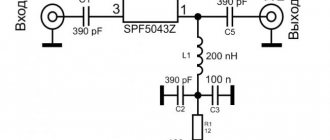
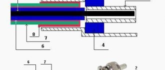
Voltage stabilization circuit: how it works
The most primitive output voltage stabilization circuit is created on the additional winding of a pulse transformer.
The voltage is removed from it and applied to adjust the signal value of the primary winding.
Better stabilization is created by monitoring the output signal from the secondary winding and separating its galvanic connection through an optocoupler.
It uses an LED through which a current passes proportional to the output voltage. Its glow is perceived by a phototransistor, which sends a corresponding electrical signal to the control circuit of the key stage generator.
The quality of output voltage stabilization can be improved by sequentially adding a zener diode to the optocoupler, as shown in the example of the TL431 microcircuit in the picture below.
To consolidate the material in your memory, I recommend watching the video of the owner of Soldering Iron TV, which explains well the information about switching power supplies: operating principles using the example of a specific model.
I hope that my article will help you repair your UPS yourself in 7 steps, which I outlined in another article.
Ask any questions you have in the comments section and express your opinion. It will be useful for other people to know it.
Formation of a square wave signal with variable frequency
If you are familiar with Arduino, then you should know that the Arduino board can quite easily generate a PWM signal (using the analogwrite function) on a number of its pins
But using this function, you can only control the duty cycle (duty factor) of the PWM signal, but you cannot control its frequency - and this is exactly what is needed for our signal generator. Controlling the frequency of the square wave signal can be done using timers on the Arduino board and directly switching the state of the contacts based on them
The Arduino PWM Frequency Library (PWM signal frequency control library) can help us with this; we will look at working with it in more detail later in the article.
But there are a number of weaknesses in using this library. The fact is that this library changes the default settings of Timer 1 (Timer 1) and Timer 2 (Timer 2) of the Arduino board. In this regard, you will no longer be able, for example, to use the library for controlling a servomotor or other libraries that use these Arduino board timers. Also the analogwrite function on pins 9,10,11 & 13 uses Timer 1 and Timer 2, hence you will no longer be able to generate an SPWM signal (sine wave PWM signal) on these pins.
But the advantage of this library is that it does not interfere with the operation of Timer 0 (Timer 0) of the Arduino board, which in our case is more important than Timer 1 and Timer 2 because in this case you can easily use the delay function and millis() function. Also, pins 5 and 6 are controlled by Timer 0, so we can easily use the analogwrite function on these pins or control a servomotor.
Voltage stabilization circuit: how it works
The most primitive output voltage stabilization circuit is created on the additional winding of a pulse transformer.
The voltage is removed from it and applied to adjust the signal value of the primary winding.
Better stabilization is created by monitoring the output signal from the secondary winding and separating its galvanic connection through an optocoupler.
It uses an LED through which a current passes proportional to the output voltage. Its glow is perceived by a phototransistor, which sends a corresponding electrical signal to the control circuit of the key stage generator.
The quality of output voltage stabilization can be improved by sequentially adding a zener diode to the optocoupler, as shown in the example of the TL431 microcircuit in the picture below.
To consolidate the material in your memory, I recommend watching the video of the owner of Soldering Iron TV, which explains well the information about switching power supplies: operating principles using the example of a specific model.
I hope that my article will help you repair your UPS yourself in 7 steps, which I outlined in another article.
Ask any questions you have in the comments section and express your opinion. It will be useful for other people to know it.
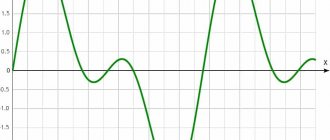
Control of multi-level sinusoidal PWM (MSPWM)[ | ]
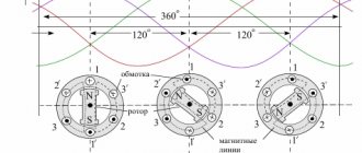
Voltage at the inverter section. (a) Output voltage using PWM. (b) Output voltage with added sinusoidal third harmonic. Several techniques have been developed to reduce distortion in multi-level inverters, based on the classic triangular carrier PWM. Some methods use the location of the source, others use the phase shift of multiple carrier signals. The figure on the right shows the typical voltage generated by one section of the inverter by comparing a sine wave with a triangle carrier signal.
Multiple Nc stages in phase with their sources offset by θc = 360°/Nc and using the same control voltage produce the lowest distortion load voltage. This result was obtained for a multi-element inverter in a seven-level configuration, which uses three series-connected segments in each phase. The smallest distortion is obtained when the source is shifted by an angle of θс = 360°/3 = 120°.
A fairly common practice in industrial applications for a multi-level inverter is to insert a third harmonic into each segment, as shown in Figure right(b), to increase the output voltage. Another positive side of multi-level PWM is the effective switching frequency of the load voltage is Nc times, and the switching frequency of each segment, depending on its carrier signal. This property allows the switching frequencies of each segment to be reduced, thereby reducing switching losses.