Scope of application of time relay
Man has always sought to make his life easier by introducing various devices into everyday life.
With the advent of electric motor-based equipment, the question arose of equipping it with a timer that would control this equipment automatically. Turn it on for a specified time - and you can go do other things. The unit will switch itself off after the set period. For such automation, a relay with an auto-timer function was required.
A classic example of the device in question is in a relay in an old Soviet-style washing machine. On its body there was a handle with several divisions. I set the desired mode, and the drum spins for 5–10 minutes until the clock inside reaches zero.
The electromagnetic time relay is small in size, consumes little electricity, has no breakable moving parts and is durable
Today, time relays are installed in various equipment:
- microwaves, ovens and other household appliances;
- exhaust fans;
- automatic watering systems;
- automatic lighting control.
In most cases, the device is made on the basis of a microcontroller, which simultaneously controls all other operating modes of automated equipment. It's cheaper for the manufacturer. There is no need to spend money on several separate devices responsible for one thing.
Based on the type of element at the output, time relays are classified into three types:
- relay – the load is connected via a “dry contact”;
- triac;
- thyristor.
The first option is the most reliable and resistant to network surges. A device with a switching thyristor at the output should be used only if the connected load is insensitive to the shape of the supply voltage.
To make your own time relay, you can also use a microcontroller. However, homemade products are mainly made for simple things and work conditions. An expensive programmable controller in such a situation is a waste of money.
There are much simpler and cheaper circuits based on transistors and capacitors. Moreover, there are several options; there is plenty to choose from for your specific needs.
The simplest 12V timer at home
The simplest solution is a 12 volt time relay. Such a relay can be powered from a standard 12v power supply, of which there are many sold in various stores.
The figure below shows a diagram of a device for turning on and automatically turning off a lighting network, assembled on one integrated counter of the K561IE16 type.
Drawing. A variant of a 12v relay circuit that turns on the load for 3 minutes when power is applied.
This circuit is interesting in that the flashing LED VD1 acts as a clock pulse generator. Its flicker frequency is 1.4 Hz. If you cannot find an LED of this particular brand, you can use a similar one.
Let's consider the initial state of operation, at the moment of supplying 12v power. At the initial moment of time, capacitor C1 is fully charged through resistor R2. Log.1 appears at pin No. 11, making this element zeroed.
The transistor connected to the output of the integrated meter opens and supplies 12V voltage to the relay coil, through the power contacts of which the load switching circuit is closed.
The further principle of operation of the circuit, operating at a voltage of 12V, is to read the pulses coming from the VD1 indicator with a frequency of 1.4 Hz to pin No. 10 of the DD1 counter. With each decrease in the level of the incoming signal, there is, so to speak, an increment in the value of the counting element.
When the 256th pulse arrives (this equals 183 seconds or 3 minutes), a log appears on pin No. 12. 1. This signal is a command to close transistor VT1 and interrupt the load connection circuit through the relay contact system.
At the same time, logic 1 from pin No. 12 is supplied through diode VD2 to clock leg C of element DD1. This signal blocks the possibility of receiving clock pulses in the future; the timer will no longer operate, until the 12V power supply is reset.
The initial parameters for the operation timer are set in different ways by connecting the transistor VT1 and the diode VD3 indicated in the diagram.
By slightly transforming such a device, you can make a circuit that has the opposite principle of operation. The KT814A transistor should be changed to another type - KT815A, the emitter should be connected to the common wire, the collector to the first contact of the relay. The second relay contact should be connected to a 12V supply voltage.
Drawing. A variant of a 12v relay circuit that turns on the load 3 minutes after power is applied.
Now, after power is applied, the relay will be turned off, and the control pulse that opens the relay in the form of logic 1 output 12 of element DD1 will open the transistor and supply 12V voltage to the coil. After which, the load will be connected to the electrical network through the power contacts.
This version of the timer, operating from a voltage of 12V, will keep the load disconnected for a period of 3 minutes, and then connect it.
When making the circuit, do not forget to place a capacitor with a capacity of 0.1 μF, designated C3 in the circuit and a voltage of 50V, as close as possible to the supply terminals of the microcircuit, otherwise the counter will often fail and the relay dwell time will sometimes be less than it should be.
In particular, this is programming the exposure time. By using, for example, a DIP switch as shown in the figure, you can connect some contacts of the switches to the outputs of the counter DD1, and combine the second contacts together and connect them to the connection point of the elements VD2 and R3.
Thus, using microswitches you can program the relay delay time.
Connecting the connection point of elements VD2 and R3 to different outputs of DD1 will change the dwell time as follows:
| Counter leg number | Counter digit number | Exposure time |
| 7 | 3 | 6 sec |
| 5 | 4 | 11 sec |
| 4 | 5 | 23 sec |
| 6 | 6 | 45 sec |
| 13 | 7 | 1.5 min |
| 12 | 8 | 3 min |
| 14 | 9 | 6 min 6 sec |
| 15 | 10 | 12 min 11 sec |
| 1 | 11 | 24 min 22 sec |
| 2 | 12 | 48 min 46 sec |
| 3 | 13 | 1 hour 37 min 32 sec |
Connection diagrams for a magnetic starter with a 220 V coil
Before we move on to the diagrams, let’s figure out what and how these devices can be connected. Most often, two buttons are required - “start” and “stop”. They can be made in separate housings, or they can be a single housing. This is the so-called push-button post.
Buttons can be in the same housing or in different ones
Everything is clear with individual buttons - they have two contacts. One receives power, the other leaves it. There are two groups of contacts in the post - two for each button: two for start, two for stop, each group on its own side. There is also usually a ground terminal. Nothing complicated either.
Connecting a starter with a 220 V coil to the network
Actually, there are many options for connecting contactors; we will describe a few. The diagram for connecting a magnetic starter to a single-phase network is simpler, so let's start with it - it will be easier to understand further.
Power, in this case 220 V, is supplied to the coil terminals, which are designated A1 and A2. Both of these contacts are located at the top of the case (see photo).
This is where you can supply power to the coil.
If you connect a cord with a plug to these contacts (as in the photo), the device will be in operation after the plug is inserted into the socket. In this case, any voltage can be applied to the power contacts L1, L2, L3, and it can be removed when the starter is triggered from contacts T1, T2 and T3, respectively. For example, a constant voltage from a battery can be supplied to the inputs L1 and L2, which will power some device that will need to be connected to the outputs T1 and T2.
Connecting a contactor with a 220 V coil
When connecting single-phase power to the coil, it does not matter which output is supplied with zero and which with phase. You can switch the wires
Even most often, the phase is supplied to A2, since for convenience this contact is located on the bottom side of the case
And in some cases it is more convenient to use it and connect the “zero” to A1
Even most often, the phase is supplied to A2, since for convenience this contact is located on the bottom side of the housing. And in some cases it is more convenient to use it and connect the “zero” to A1.
But, as you understand, this scheme for connecting a magnetic starter is not particularly convenient - you can also supply conductors directly from the power source by building in a regular switch. But there are much more interesting options. For example, you can supply power to the coil through a time relay or a light sensor, and connect the street lighting power line to the contacts. In this case, the phase is connected to contact L1, and zero can be taken by connecting to the corresponding coil output connector (in the photo above it is A2).
Diagram with start and stop buttons
Magnetic starters are most often installed to turn on an electric motor. It is more convenient to work in this mode if there are “start” and “stop” buttons. They are connected in series to the phase supply circuit to the output of the magnetic coil. In this case, the diagram looks like the figure below
note that
Switching diagram of a magnetic starter with buttons
But with this method of switching on, the starter will operate only as long as the “start” button is held down, and this is not what is required for long-term operation of the engine. Therefore, a so-called self-catching circuit is added to the circuit. It is implemented using auxiliary contacts on the starter NO 13 and NO 14, which are connected in parallel with the start button.
Connection diagram for a magnetic starter with a 220 V coil and a self-retaining circuit
In this case, after the START button returns to its original state, power continues to flow through these closed contacts, since the magnet has already been attracted. And power is supplied until the circuit is broken by pressing the “stop” key or by triggering a thermal relay, if there is one in the circuit.
Power for the motor or any other load (phase from 220 V) is supplied to any of the contacts marked with the letter L, and is removed from the contact marked T located underneath it.
It is shown in detail in what order it is better to connect the wires in the following video. The whole difference is that not two separate buttons are used, but a push-button post or push-button station. Instead of a voltmeter, you can connect a motor, pump, lighting, or any device that operates on a 220 V network.
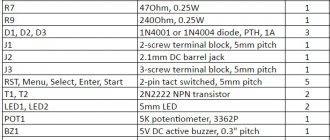
Homemade product based on NE 555 timer
Another electronic timer circuit for DIY assembly is also easy and easy to repeat. The heart of this circuit is the NE 555 integrated timer chip. This device is designed to both turn off and turn on devices; below is a diagram of the device:
NE555 is a specialized chip used in the construction of all kinds of electronic devices, timers, signal generators, etc. It is common enough that it can be found in any radio store. This microcircuit controls the load through an electromechanical relay, which can be used to both turn on and off the payload.
The timer is controlled by two buttons: “start” and “stop”. To start counting the time, you must press the “start” button. The device is turned off and returned to its original state using the “stop” button. The node that sets the time interval is a chain of variable resistor R1 and electrolytic capacitor C1. The value of the delay for switching on the time relay depends on their rating.
With the given values of elements R1 and C1, the time range can be from 2 seconds to 3 minutes. An LED connected in parallel to the relay coil is used as an indicator of the operating status of the structure. As in the previous circuit, its operation requires an additional 12 Volt external power source.
In order for the relay to turn on itself immediately when power is applied to the board, it is necessary to slightly change the circuit: connect pin 4 of the microcircuit to the positive wire, disconnect pin 7, and connect pins 2 and 6 together. You can learn more clearly about this scheme from the video, which describes in detail the process of assembling and working with the device:
Example of installation in a steam boiler
So why did I go to the store to buy this relay?
Now there will be a terrible story. The fact is that at our enterprise in the boiler room there is an Italian steam boiler (steam generator), which provides steam for the technological process and for heating.
I upgraded this boiler, about which there was already an article on the blog Using a soft starter.
One Saturday in March, the engineer on duty called me and said that we had an emergency - the fan motor on the boiler did not turn on. More precisely, it launches into “Star”, but does not go to “Triangle”. Accordingly, the air pressure in the burner does not reach the required value, and the boiler “goes into error.”
Here's the engine:
Motor with star-delta connection circuit
Engine nameplate that switches from Star to Delta
Connecting the motor in a boron box:
Connecting the motor in the terminal box
The culprit of the emergency situation, when the premises were left without heating and the enterprise without production, turned out to be a time relay for starting the Siemens Sirius 3RP1574 engine. This relay worked for more than 8 years, and then it was done.
Siemens time relay for the Star-Delta engine starting circuit, top view, on the supply contacts
The “old” relay was less functional than the model from F&F - the delay time range is only from 1 to 20 s, there is no separate connection of internal relay contacts, and there is no adjustment of the switching time.
Siemens timing relay for Star-Delta motor starting circuit
The time setting was 9 s. Video of how it happened:
Of course, there was a controller in the boiler, but this controller is not a simple one, but a specialized one for boilers, in which all European safety standards are met. And no one even thought about using it to control the start of the burner engine.
Instead of a time relay for starting the Siemens Star-Delta engine, an F&F PCG-417 relay was installed.
The photo below shows the operation of this relay in “Star” mode. Contactors CV (common, KM1) and CVS (Star, KM2) are switched on, the red indicator is flashing:
Switching on relays and contactors in Zvezda
Next, “Triangle” is turned on. Contactors CV (common) and CVT (Triangle, KM3) are turned on, the red indicator lights up steadily:
Switching on relays and contactors in Triangle
The same thing is in the video:
The video shows that the engine does not have time to accelerate in 5 seconds, so the time was increased.
A closer look at the front panel of the relay. The regulator is set to 10 s:
Switching on the star-delta time relay F&F PCG-417
Everything worked. No more than 2 hours passed from the moment of purchase to the moment of starting the boiler. At the time of writing, the FiF time relay has been operating in the boiler burner for more than 1.5 years without failure.
How to make a time relay: two best ways
Thanks to a time relay, you can seriously save money. For example, it can be installed in a closet, corridor or entrance; with one click you can turn on the light, and after a certain period of time it will turn off automatically. This time will be enough for you to find an item in the pantry or simply go through an area in the corridor. In this article we will tell you how to make a time relay with your own hands, consider step-by-step instructions and the simplest connection diagrams.
How to make a time relay - the easiest option
We understand that the bulk of our readers are amateurs. Therefore, we decided not to go into complex technical terms that can be confusing. Especially for our subscribers, we found this video, after watching which you can understand how to make a homemade timer to turn off the electricity.
We would like to draw your attention to the fact that you should not have any difficulties, because the instructions are extremely simple to understand. To make a time relay we need the following materials:
To make a time relay we need the following materials:
The time relay connection diagram looks like this:
The capacitor here is C1. The delay time of such a relay is 10 minutes. If we talk about other characteristics of the kit, it boasts 1000 uF/16 Volts. The time is adjusted using a standard resistor R1. The device is controlled using contacts; there is no need to make a special board for it; it can be assembled as shown in the breadboard.
Assembling a time relay based on the NE 555 timer
The second time relay circuit is also elementary. But, to assemble it, we need a NE 555 timer. This timer is designed to turn on and off various devices. Its diagram looks like this.
The main component of this device is a microcircuit; it is used in the construction of the most popular electrical devices and timers. The microcircuit allows you to control the load using a special electromechanical relay. Therefore, you can configure it to turn the light off and on.
Controlling this timer is quite simple; on the body you will find two buttons:
To start the time, you must press the “start” button. If you need to return to the original state, then press “stop”
Note that the time interval is controlled by resistor R1 and capacitor C1. The time after which a lamp or other lighting device will go out depends on their nominal value.
You can set the time from two seconds to three minutes. So you can easily find the best shutdown time. This model requires constant power from a 12 Volt source.
You can learn more about it by watching this video.
We recommend reading: how to install a headlight strip.
dekormyhome.ru
Characteristics and selection criteria
First of all, you need to decide on the type of relay used. It must be equipped with a built-in light sensor or an external one. The remote one is small in size, it is easier to protect it from backlighting, the device itself can be installed at home, for example, in a distribution panel. There are even modifications for DIN rail.
A photo relay equipped with a built-in light sensor should be located close to the lighting fixture
Also, during installation, it is important to take into account that the lamp light can affect the photosensor; this should be avoided. A day-night sensor with a built-in element is preferable to use, for example, for solar-powered lamps
Performance characteristics
Classification of degrees of protection
Technical parameters of possible modifications:
- Load power. Each sensor is designed to operate at a specific load power. It is recommended that the power of all lighting fixtures be approximately 20% less than rated. In this case, the equipment will not always be overloaded, which will have a positive effect on its service life.
- Housing protection class. Devices intended for outdoor use must have a protection class of at least IP44. This indicates that dust and water particles larger than 1 mm in size will not be able to penetrate into the housing. Outdoors you can install devices with an even higher protection class, but less is not possible. For home use, you can purchase designs with IP23 protection.
- Mode of use. If the light bulb timer will operate year-round, it must be designed to operate in low and high temperatures. It is recommended to take indicators with a margin in case of abnormal heat or cold weather.
- Supply voltage. It can be either 220V or 12V. The choice mainly depends on the type of voltage that powers the street lighting. 12V lighting fixtures can also be used with rechargeable batteries.
Customization options
Setting the sensitivity of the photo relay
There are several adjustments that will allow you to customize the operation of the sensor for a specific situation. Equipment settings at the initial stage of use are carried out manually by turning the required regulator. It is almost impossible to achieve the same parameters.
- Adjustable light range. Thanks to this parameter, the lighting is set at which the relay closes and opens the contacts. The range can vary from 2 to 100 Lux in complete darkness, and from 20 to 80 Lux at twilight.
- The response threshold allows you to reduce or increase light sensitivity. It is recommended to reduce this parameter in winter, when there is snow on the ground and the sensors react to it. It is also reduced if brightly lit objects are located in close proximity.
- Delay, measured in seconds, for turning off and on. By increasing the shutdown delay, the number of false alarms is reduced, for example, when light from a car's headlights hits the sensor. The turn-on delay, in turn, will prevent the lighting device from being turned on when it is darkened by the shadow of a bird or a cloud.
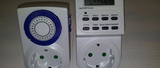
Liquid crystal display
LCD Display Data
At the top of the display: days of the week MO - Monday; TU - Tuesday; WE—environment; TH - Thursday; FR - Friday; SA - Saturday; SU - Sunday. The day of the week is set with the D+ button. In the middle part of the display: current and programmable time. The time is set with the , H+ and M+ buttons. In the lower left part of the display: numbers of on and off cycles ON - on; OFF - disabled; numbers from 1 to 16 - cycle number. Cycles are configured using the button in the lower right part of the display: control mode ON - constantly on; AUTO - automatic mode; OFF - permanently disabled. The control mode is set using the MANUAL button
Connecting a time relay
In modern conditions, digital electronic timers are most often used. They provide stable operation, high accuracy of action and a wide range of time delay settings. The program of such devices provides for a large number of switches on and off. For normal operation of the electrical circuit, a time relay connection diagram is used.
The basis of a typical device is a microprocessor-based timer with a liquid crystal display. Programming is carried out using special buttons.
The required switching is set using a relay, which has switching contacts Nos. 3, 4, 5, shown in the figure. To supply supply voltage to the timer, there are terminals No. 1, 2. Switching contacts make it possible to perform various operations with electrical loads, not only by simply turning them on or off. They allow you to work with several electrical circuits at once, turning them on or off.
Thus, the scope of use of time relays is significantly expanded. This allows you to illuminate large areas one at a time by automatically turning the lights off and on. This results in significant savings in electrical energy.
The principle of alternately turning on and off different lighting groups is actively used in private country houses. The lights turn on automatically in different rooms, creating the illusion of the presence of the owners. This measure very effectively prevents theft during periods of prolonged absence of residents. The power supply to the load and the time relay is carried out separately and is in no way connected with each other. This allows you to set the control of loads with high powers, up to 380 volts.
Advantages and disadvantages of the device
One of the advantages of the relay is its large range of settings
The advantages of electronic products are manifested in their high reliability and functionality. Disadvantages include the limited intervals for which the relay can be configured during programming, as well as the high cost in comparison with electromagnetic samples.
The main advantages of e/m devices are:
- relatively low cost combined with a wide range of settings - the ability to set daily intervals;
- simplicity of design compared to electronic models;
- no need to program and adjust time relay settings to turn on lights or power equipment.
The disadvantages of these devices include a limited service life, as well as some difficulties with installation and use in DC circuits.
How to connect a relay
If frequency converters are used when connecting industrial or household equipment, then the use of a phase control relay is not at all necessary.
Direct connection is carried out according to the instructions on how to connect a relay of this particular type. Quite often the connection diagram is shown on the device body
To do this, you should pay attention to various photos of phase control relays.
Connection to external and internal sources is carried out using wires with clamps. Either one wire with a cross-section of 2.5 mm or two wires with a cross-section of up to 1.5 mm are supplied under it. To connect, it is necessary to observe strict alternation of phases A, B and C.
Usually the relay checks the plus break, their alternation, and the network voltage level. When a fault is detected in the network, the relay comes into action. The connection diagram can be either three-wire without zero, or four-wire with zero. In apartments, this connection scheme is often used. The connected load is formed evenly on each of the 3 phases.
When any of the phases goes beyond the specified values, the relay responsible for this circuit is activated, and the rest of the load (provided it is within the required range) continues to operate.
Let's consider a connection diagram with zero. This circuit provides complete control over the voltage on each phase, skew and correct alternation, and it is also worth noting the fact that they are used as an industrial option. At the output of the device, using a power contact, we connect a contactor, which with one end of its winding is connected to the neutral wire, and the other end to the output of one of the phases.
Contacts 1, 2 and 3 connect the voltage removed from the voltage control relay to any three-phase load such as an electric motor, or high-power flow heaters, etc. The internal circuit of the relay measures the voltage value on each of the phases and when U is within normal values, it supplies energy to the connected contactor. This, in turn, keeps the contacts in a closed state, and the voltage reaches the external connected load.
If the voltage on any of the phases goes beyond the range we set, the relay stops powering the winding of our contactor and it, in turn, opens its contacts, de-energizing the entire connected external load.
Example video showing the operation of a voltage relay
Special devices - voltage control relays - help solve the problem of voltage surges in networks. The principle of operation of such relays is quite simple, there is an “electronic unit” that monitors that the voltage is within the limits specified by the settings and if there are deviations, it signals the release (power section), which turns off the network. All household voltage control relays turn on automatically after a certain time. For ordinary consumers, a delay of a few seconds is sufficient, but for refrigerators and air conditioners with compressors a delay of several minutes is needed.
Voltage control relays are available in single-phase and three-phase types. Single-phase voltage relays disconnect one phase, while three-phase voltage relays disconnect all three phases at the same time. When using a three-phase connection at home, single-phase voltage relays should be used so that voltage fluctuations on one phase do not lead to the shutdown of other phases. Three-phase ones are used to protect motors and other three-phase consumers.
I divide surge protection devices into three types: UZM-51M from Meander, Zubr from Electronics and all the others. I am not imposing anything on anyone - this is my personal opinion.
Voltage relay Zubr (Rbuz)
This device is designed to protect against voltage surges (zero burnout). BISON is produced in Donetsk.
I will note the features of this voltage relay.
Voltage indication on the device – shows the voltage value in real time. This is quite convenient and necessary for assessing the voltage situation in the network. The reading error is low, the difference relative to the Fluke 87 high-precision multimeter is only 1-2 Volts.
Zubr voltage relays are produced for various rated currents: 25, 32, 40, 50 and 63A. The device, with a rated current of 63A, can withstand a current of 80A for 10 minutes.
The upper voltage value is set from 220 to 280 V in steps of 1 Volt, the lower - from 120 to 210 V. The restart time is from 3 to 600 seconds, in steps of 3 seconds.
I set the Zubr relay, the maximum (upper) voltage value is 250 Volts, and the lower value is 190 Volts.
Devices with the index t in the name, for example Zubr D63t, have thermal protection against internal overheating. Those. when the temperature of the device itself increases to 80 degrees (for example, due to heating of the contacts), it turns off.
Zubr relays occupy 3 modules or 53 mm on a DIN rail and are only single-phase.
The passport and the Zubr connection diagrams provided do not say about current limitations, but in the old documentation it was previously indicated that no more than 0.75 of the nominal.
Operating principle and applications
Electromagnetic time relay consumes little electricity
The simplest example to understand the principle of operation of a relay is a mechanical or electronic alarm clock set for a certain time. To obtain a full-fledged timer, an actuator is added to it, which performs the desired function - supplying power to a chandelier or fan, for example. The operating procedure of such a relay is:
- As soon as the time interval set on the timer (clock) has expired, the control signal is sent to the relay coil.
- Immediately after this, its working contacts open or close the supply circuit.
- As a result, the device connected to it turns off or turns on.
In real devices, a similar operating mode is implemented taking into account a predetermined time delay.
Timers of various types are widely used to control the operation of industrial installations, as well as when turning household appliances on and off. Commonly used switched household loads are:
- lighting fixtures of any class;
- various samples of climate control equipment;
- ventilation systems and similar devices.
Before you make a timer for turning electrical appliances on and off with your own hands, you will need to familiarize yourself with the types of these devices.
Types and classification
Devices such as time relays are divided into:
- block;
- modular;
- built-in
Block ones differ in the specific installation process, which requires individual power supply from the network. Built-in ones do not require a separate power supply, as they are most often used as auxiliary elements in more complex circuits. Modular time relays are also not connected to a separate power line. Modular relays are mounted on a DIN rail.
Time relays can also be:
- electromagnetic;
- pneumatic;
- electronic;
- motor.
Electronic or electromagnetic relays are mainly used for household use. This is explained by the fact that they are as efficient as possible, and their cost is low and affordable for any consumer.
What is a time relay
Programmable time relay
From French, the word “relay” is translated as “replace”, and in practice the term means an electric or electronic key, which is necessary for switching sections of electrical circuits and controlling energy consumption. This concept is typical for conventional electromagnetic devices. A programmable device, or timer, commands the connection or disconnection of electrical circuits automatically, according to the settings set by the user.
An electromechanical device closes or opens contacts when a small electrical current is applied to the relay coil. The resulting magnetic field sets in motion the “armature” to which the switching contacts are connected. Thanks to this process, the network is opened and closed. Recently, solid state relays have been widely used. They have powerful semiconductor switches and are able to withstand heavy loads.
If the circuit needs to be switched not during the signal period, but at a certain moment, a more complex device is used - a time relay (RT). They are triggered after a certain period, providing a sequence of actions. Thanks to the operating principle, it is possible to build electrical circuits of varying complexity. With the help of such circuits, control functions of various equipment are carried out.
For example, a relay is indispensable for organizing automatic watering, turning off lights in a common corridor, and turning on and off a compressor in an aquarium.
Configuring electronic-mechanical analog relays
Industrial automation systems, as well as various household modules, are often equipped with electromechanical devices, the design of which allows for adjustment using potentiometers.
Electromechanical type of time counting device with parameter adjustment by potentiometers. There are various configurations of such devices, which makes it possible to use them in circuits of varying complexity.
On the front panel of the housing of such devices there is a potentiometer rod (or several rods) designed for rotation with a screwdriver blade. A marked scale of installation values is applied around the circumference of the rod(s).
The slot on the rod for the screwdriver blade is a kind of pointer that changes its position when the rod rotates. By placing this pointer opposite certain values of the marked scale, the desired parameter can be adjusted.
Multichannel device of electronic-mechanical type. Adjustment is easy and simple by rotating the potentiometers with a screwdriver. The front panel also has LED status indication
Devices of this type (for example, NTE8 ) are widely used in control circuits for ventilation systems, heating modules, and artificial lighting devices.
Installation of a pulse relay
How to connect a pulse relay? Here you need to be guided by a diagram that facilitates installation work. In this case, the switch that controls the lighting process should not be in the open position. It has a special release spring. When pressed, it quickly triggers, thereby closing the circuit in another place.
How to connect correctly with your own hands? The scheme offers four possible solutions. One contact output is intended for connecting the power supply phase, and zero is connected to the other.
The neutral wire must be routed separately to each lighting lamp. The number of switches should not exceed the permissible value indicated in the technical data sheet of the device. If their number exceeds the permissible value, then a false operation of the device is possible.
In bipolar models, they are installed next to circuit breakers. To do this, conduct four additional wires:
- incoming phase;
- neutral contact;
- output wire for the button;
- output for powering light bulbs.
First of all, run the external output cable into the installation box. The diagram shows two switch buttons. In fact, there can be from 6 to 10 points. Here it is necessary to place the wires at a distance of 2 cm from the power contacts.
Upon completion of installation work, it is recommended to make high-quality insulation. For this purpose, heat-shrinkable cambrics are used. They will ensure tight fixation of the conductors. In addition, such insulating material will protect against short circuits between contacts during operation.
Main characteristics
Each TR has individual technical characteristics (TX). The relay must be selected according to the load characteristics and application conditions when operating an electric motor or other electrical consumer:
- Value of In.
- Adjustment range of I actuation.
- Voltage.
- Additional control of TR operation.
- Power.
- Trigger limit.
- Sensitivity to phase imbalance.
- Trip class.
The rated current value is the value of I for which the TR is designed. Selected according to the value of In of the consumer to which it is directly connected. In addition, you need to choose with a margin of Inr and be guided by the following formula: Inr = 1.5 * Ind, where Inr – In TR, which should be 1.5 times greater than the rated motor current (Ind).
The adjustment limit of I operation is one of the important parameters of the thermal protection device. The designation of this parameter is the range of adjustment of the value of In. Voltage – the value of the power voltage for which the relay contacts are designed; If the permissible value is exceeded, the device will fail.
Some types of relays are equipped with separate contacts to control the operation of the device and the consumer. Power is one of the main parameters of the TP, which determines the output power of the connected consumer or group of consumers.
The operation limit or operation threshold is a coefficient depending on the rated current. Basically, its value is in the range from 1.1 to 1.5.
Sensitivity to phase imbalance (phase asymmetry) shows the percentage ratio of the phase with imbalance to the phase through which the rated current of the required value flows.
Trip class is a parameter representing the average response time of the TP depending on the multiple of the setting current.
The main characteristic by which you need to select a TR is the dependence of the response time on the load current.
Instruments with mechanical scale
One of the devices that has a mechanical scale is a household timer. It works from a regular outlet. Such a device allows you to control home appliances within a certain time range. It contains a “socket” relay, which is limited by the daily operating cycle.
To use the daily timer, you need to configure it:
- Raise all the elements that are located along the disc circumference.
- Omit all elements that are responsible for setting the time.
- Scroll the disk and set it to the current time period.
For example, if the elements are omitted on the scale marked 9 and 14, then the load will be activated at 9 a.m. and will be turned off at 2 p.m. You can create up to 48 device activations per day.
To do this, you need to activate the button located on the side of the case. If you start it, the timer will start in urgent mode, even if it was turned on.
https://youtube.com/watch?v=VRrU_eYT2l4
Diagram of operation of the ECM pressure gauge together with the starter and relay
With the appearance of more and more technical innovations on the market, a lot of questions arise about how to use them. I will talk about one such device, namely the ECM electrical contact pressure gauge, in my article.
This device is used to monitor pressure in water supply systems (plumbing can be considered as a special case).
The units that incorporate this device also help control the active elements of the system (for example, pumps).
This device can easily act as an alternative to a pressure switch. They can easily change the pressure control relay, because the ECM can fully cope with the task of turning the same pump on and off.
Before considering the circuit for switching on the pressure gauge, it would be a good idea to familiarize yourself with the pressure gauge itself and its principle of operation, as well as analyze its positive and negative aspects in relation to the relay that controls the pressure.
Using a push-button station in conjunction with a time relay
You can realize the possibility of starting the engine not only from a time relay, but also from a push-button station by adding a second starter and assembling a special “pick-up” circuit.
Appearance of a push-button post with two buttons
Let's look at the circuit diagram below. When you press the “START” button, Starter 1 is activated and the corresponding contact K1.1, connected in parallel to the “START” button, is closed. When this button is released, the supply voltage continues to maintain Starter 1 in the on state and, accordingly, the parallel contact K1.1 in the closed state.
Simultaneously with contact K1.1, contact K1.2 closes, which directly turns on Starter 2, which controls the load. At the moment the time relay is triggered, the “time relay contact” is triggered and Starter 2 is turned on.
When you press the “STOP” button (it is closed by default), the circuit opens and Starter 1 is turned off. The state of Starter 2 will depend only on the state of the time relay.
The starter can control, for example, a motor or something else. If the number of its contacts is not enough, then their number can be increased with special attachments.
Operating algorithms, functional diagrams, symbols
Functional diagram of a two-channel time relay
Modern programmable devices provide a complex operating algorithm, including time pauses and cyclically repeating intervals. There are the following operating schemes for time relays:
- simple switch-on delay;
- after power is applied, the load is connected, but after a time specified by the program, the voltage is removed from it;
- the same as in the previous case, but the shutdown occurs with some delay.
Another scheme assumes a more complex cyclic mode of operation of the device. To understand it, you should clarify the procedure for turning on and off the load. It looks like this:
- After supply, the food arrives as intended only after a certain period of time.
- The line remains connected to the network for a predefined interval.
- There is a shutdown and a pause equal to its duration when power is applied.
- The load is reconnected for the same time as the first time.
- The sequence of these actions continues until the supply voltage is completely removed.
When studying the algorithms for operating a time relay and the features of its application, you will need to become familiar with one of the most important characteristics of the device, presented in the form of a functional diagram.
Trigger diagrams
Time relay operation diagrams
This characteristic refers to graphic diagrams that describe the state of the time relay at different times. When you get acquainted with them, the entire switching process is presented in a visual form.
The cyclic nature of the processes observed when devices operate according to a complex algorithm is especially clearly distinguishable in the diagrams. The time intervals indicated on them are usually set by the user himself. On the other hand, there are known examples of devices in which the moments of disconnecting and connecting the load cannot be adjusted. As a fixed parameter, they are usually indicated in the product passport. Most often, these are special-purpose timing devices installed in the protective circuits of industrial installations.
Contact designations on diagrams
Graphic designation of contacts
When choosing a time relay, it is important to learn to understand not only the functional diagrams of operation, but also the layout of its working contacts. Among them, the following types of contact groups stand out:
- one of them is always open in the non-working position;
- the other group of contacts is in a closed state under normal conditions;
- the third variety has a neutral position.
To understand the nature of relay operation in the diagrams, they are indicated by special icons in the form of semi-ovals, straight line segments and truncated parallels.
What kind of sensor is this and when is it used?
An electric contact pressure gauge is a sensor that is used to measure excess and vacuum pressure in various media (liquid, gas, steam), is used as a direct-acting signaling device and allows you to control production processes, while a special condition for the medium is to prevent its crystallization.
The ECM is used to issue control signals to actuators that maintain pressure values in the pipeline, as well as compressor units, hydraulic systems, pneumatic equipment or household autoclaves at a certain value.
The electrical contact pressure gauge is popular in many industries and infrastructure systems:
- Energy;
- Metallurgy;
- Oil and gas and petrochemical industry;
- Water supply systems;
- Mechanical engineering installations;
- Heat generation and distribution.
ECMs are also in demand in safety automation systems of thermal power plants, central heating stations and boiler houses.
Types of sensor models
There are many manufacturers involved in the production of electrical contact pressure gauges; some offer a fairly wide range of models; the list below is divided according to various manufacturing plants:
- TM (TV, TMV), 10th series;
- PGS23.100, PGS23.160;
- EKM100Vm, EKM160Vm;
- TM-510R.05, TM-510R.06, DM2005Sg and its analogue TM-610.05 ROSMA.
All of the listed models are divided into pressure gauges with microswitches and with magnetomechanical contacts. Manufacturers also produce devices that are explosion-proof and vibration-resistant or liquid-filled (filled inside with dielectric oil, most often glycerin) so that the readings of the pressure gauge needle do not jump when there is increased pulsation of the measured medium. Glycerin inside the ECM will prevent the needle from moving quickly.
Operating principle of electrical contact pressure gauges
The principle of operation of the ECM is that a moving contact closes or opens a certain set value. The movable contact of an electric contact pressure gauge is a pressure indicating arrow, which rotates when the pressure in the measured medium changes. The setpoint (adjustable) value is set manually using two arrows (minimum and maximum value). These pressure gauge needles are stationary after setting the values.
The value of the moving arrow in the working process, as a rule, is between two setpoints, but when it crosses the limit value, the contacts of the internal electrical circuit are closed or opened (depending on the type of model). These contacts can be used in various relay circuits to control, for example, pneumatic or solenoid valves, as well as magnetic starters of various motors.
Note! The switching capacity of the contacts of an electrical contact pressure gauge does not allow switching large load currents. Each electrical contact pressure gauge is marked with a marking that describes all its characteristics and type.
Each electrical contact pressure gauge has a marking that describes all its characteristics and type.
Do-it-yourself homemade electrical contact pressure gauge
Hello! Many people know firsthand about such a measuring device as a pressure gauge. But many people find it difficult to imagine the device and the principle of its operation.
A pressure gauge is designed to measure the pressure of a liquid or gas. Moreover, the pressure gauge for measuring gas and liquid pressure is not structurally different from each other. So if you have a pressure gauge lying around somewhere to measure liquid pressure, then you can safely use it to measure gas pressure and vice versa.
Design and principle of operation of the pressure gauge
To better understand how the pressure gauge works and works, look at the figure below.
The pressure gauge consists of a body with a measurement scale, a copper flat tube 1 folded in the shape of a circle, a fitting 2, a transmission mechanism 3 from the tube to the pointer 4. Using the fitting, the pressure gauge is wrapped in a vessel where the pressure of the medium (gas or liquid) is to be measured.
How does a pressure gauge work?
When gas and liquid under pressure are supplied through fitting 2, the folded tube 1 will tend to straighten, and through the transmission mechanism the movement of the tube will be transmitted to the arrow 4. It, in turn, will indicate the amount of pressure, which can be read using a scale. When the pressure decreases, the tube will collapse again and the arrow will indicate a decrease in pressure.
Electric contact pressure gauge device
I think you can guess how an electric contact pressure gauge works. Its design is no different from a conventional pressure gauge, except that it has built-in contacts. There are usually two of them and their position on the pressure gauge scale can be changed.
What if you don’t have an electrical contact pressure gauge, but you really need one? What to do then? Then you need to make a homemade electric contact pressure gauge.
I'll tell you how to make a homemade electric contact pressure gauge. To do this, you will need a simple pressure gauge, two small strips of tin from a tin can, double-sided tape and two thin wires.
Using a sharp awl, pry up and remove the large retaining ring. Then remove the glass and then the rubber washer. Drill two holes in the pressure gauge housing to allow two wires to pass through them.
Cut two strips from tin and bend them in the shape of the letter L. Solder a thin insulated wire to the base. From double-sided tape, cut two strips equal in size to the strips and stick it on the strips. Next, glue the resulting contacts to the pressure gauge scale within the specified pressure limits.
Pass the wires through the holes and bring them out.
Reinstall the rubber gasket and then the glass. Secure everything with a locking ring. That's it, the homemade electric contact pressure gauge is ready. For example, I used this in a homemade automatic water supply system for a private house.
Connection diagram for electrical contact pressure gauge
In order for this pressure gauge to influence any actuator, a special circuit is needed. You can see an example of this scheme in the figure below.
At a minimum pressure of the medium (gas or liquid) in the electric contact pressure gauge, contacts 1 and 2 will be closed. In this case, the electromagnetic relay K1 will operate. It, in turn, with its contacts K1.1 will supply power to the winding of the magnetic starter K3. Using contacts K3.1, it will bypass contacts K1.1, and when the contacts in pressure gauge 1 and 2 open, relay K1 will release its contacts K1.1. But at the same time, the starter winding K3 will continue to flow around with current. With its contacts K3.2, the magnetic starter will supply power to the motor M of the pump or compressor.
With a further increase in pressure in the pressure gauge, contacts 1 and 3 close. At the same time, the electromagnetic relay K2 will operate and with its contacts will open the power circuit of the coil K3 of the magnetic starter. Contacts K3.2 will open and the power supply to motor M will disappear. With a further decrease in pressure and the closure of pressure gauge contacts 1 and 2, the cycle will repeat.
Principle of operation
The presence of relays in a specific circuit allows you to assemble devices that are more flexible in controllability. Moreover, a large number of solutions can be implemented. Therefore, it is necessary to consider each design proposal separately. Depending on the type of activity performed, electromagnetic, electronic and pneumatic systems, as well as solutions for clock mechanisms, are used in practice.
Electromagnetic devices, as a rule, can only be used in circuits with a constant current source. The duration of action is usually 0.06−0.1 seconds. for turning on and 0.6−1.4 for turning off. Such relays contain two working layers of winding, one of them is a short-circuited ring-shaped circuit.
When electric current is applied to the first winding, the magnetic flux increases. It generates current in the second winding, as a result of which the growth of the main flux stops. As a result, a time characteristic of the displacement of the armature of the mechanism appears, and a time delay is formed.
Relay Coil Disconnection
When the relay coil is turned off, it is also possible to achieve a slow decline in the magnetic flux in the magnetic circuit (Fig. 2 b). For this, various dampers are used. A damper is a thick sleeve made of copper or aluminum, which is mounted on a common core with a retractor coil. This sleeve creates a secondary circuit. When the main magnetic flux disappears when the RP is opened, a current is induced in the sleeve, which, according to Lenz’s rule, tends to maintain the main flux. The greater the mass of the damper, the longer the relay time delay. The aluminum base of the relay also plays the role of a damper. Various relay delay ranges (0.3-5.5 sec) are achieved through the use of additional removable dampers.
It should be borne in mind that the RE-500 type relay is designed for direct current, and it is connected to the control circuit of AC motors through rectifiers.