Home » Lighting » Transformers » Isolation transformer 220V/220V, 380V/220V, 380V/380V, 220V/12V
If you are planning to purchase an isolation transformer, then remember that this device is designed to convert voltage and alternating current. It is these devices that can use the same voltage at the input and output.
In this article we have provided you with detailed information. If you don't know what an isolation transformer looks like, then this article will help you find that information.
How the device protects electrical appliances
Our homes are filled with household appliances and equipment that are connected to the power grid. Electrical appliances themselves are safe to use, which is ensured by manufacturers during their manufacture and is guaranteed by appropriate quality certificates.
However, a number of unfavorable factors affecting devices and network wiring in each individual room can worsen their insulation and create conditions for the passage of current through the human body, which will lead to electrical injury. These factors include:
- heat;
- humidity in the air and in the places where the wiring passes;
- the presence of metal products with unstable grounding;
- mechanical damage to the insulation.
Compact isolation transformer.
When an electric current leaks, voltage appears on the metal surfaces of not only the devices themselves, but also on pipelines or other metal objects surrounding the user.
The highest risk of electric shock is in the bathroom. Because it contains all the negative factors affecting insulation.
Electric shock can be avoided by using protective measures. This is a reliable grounding of the housings of electrical appliances, so that in the event of accidental insulation breakdowns, dangerous currents pass through the grounding circuits.
They are also protected by the use of RCDs or differential circuit breakers in the input load connection circuits, which disconnect the network in the event of ground leaks.
Such protection measures are based on the fact that the ground for all electricity consumers is part of the electrical circuit. Protective electrical grounding simply bridges the circuit that may arise between a phase accidentally falling on the electrical equipment body and the ground through the human body in case of accidental contact.
Interesting read: how to assemble a Tesla coil yourself.
Another method of protection would be to exclude the connection of the earth with the electrical network and this can be achieved through complete galvanic isolation of the primary and secondary electrical networks. This is achieved by using safe isolation transformers, the devices of which will be discussed below.
The specific nature of some household appliances, such as a washing machine or hair dryer, requires them to be constantly connected to the power grid in conditions of high humidity, which increases the risk of electric shock from a faulty appliance or broken wiring.
Accidental touches to the conductive phases and the neutral wire will lead to tragic consequences. The 220 V voltage from the power supply network is formed according to the connection scheme of all three circuits with a potential difference of 380 V between them with a neutral wire, which is connected (grounded, as they say in everyday life) to a potential in the ground.
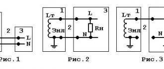
Connection diagram of the isolation transformer and devices to it.
This scheme predetermines the presence of phase voltage between each of the three network linear wires (colloquially referred to as phases) and zero (neutral) - ground. If the conductor insulation is broken, the phase voltage passes to the housing of the household appliance.
Simultaneous contact by the user of such a “broken” case and grounded metal objects such as heating radiators, faucets or water taps provokes the passage of electric current through the human body with all traumatic consequences.
Application
Experts know that this equipment can be used not only in everyday life, but also in production. This is because the device is easy to use. It is also considered quite safe during operation. Many experts claim that the device can operate even in conditions of increased electrical safety. If you are interested, then you can read about the ideal transformer.
The device can be especially useful if you are planning to make repairs. Also, if necessary, the isolation transformer can be used for wet rooms. You should not do the installation yourself. If you do not have specific knowledge, then it is better to call a specialist who will quickly complete the installation.
Operating principle of the device
The operation of a low voltage isolation step-down transformer is based on the galvanic isolation effect. Technically, this is implemented in the form of autonomous operation of both coils. The coils of the device are physically separated, that is, they do not touch each other.
This ensures safe operation provided that the circuits are not short-circuited due to mechanical stress. To completely eliminate the possibility of contact, the windings are insulated with several layers of high-quality insulation.
Isolation transformer circuit.
Passing through the primary winding, the current induces electricity in the secondary coil, to which circuits with consuming equipment are connected. The secondary winding of the RT or devices connected to it cannot have contact with ground or neutral.
It will be interesting➡ What is a traction substation
Significant increase in operational safety even in the event of a breakdown in the housing. With this scheme, a breakdown will not cause a current overload in the circuit, and the device itself will remain fully functional.
If a person comes into contact with an electrical appliance under emergency voltage connected through an isolation transformer, there will be no fatal injury from leakage current. Since it will not exceed a life-threatening level.
One of the operational features of isolation voltage transformers is the conversion coefficient equal to unity for most used models. Thus, both the input and output voltage are equal to the same value - 220 or 380 V.
When making calculations, it is necessary to take into account the energy costs for the operation of the device, since the efficiency of most models is in the range of 70-85%.
Is it necessary to install an RCD for a 220V/220V isolation transformer?
At first glance it may seem that installing an RCD is not required, but this is not the case. Damaged insulation may expose the equipment to hazardous potential. If you touch the equipment and at the same time an object connected to the ground, there is a danger of electric shock. So an RCD must be installed for complete safety.
For more information about whether you need to install an RCD, read the article: “Why do you need to install an RCD?”
Rate the quality of the article:
Types of devices
At the moment, in electrical engineering, most transformers provide galvanic isolation of input and output circuits. Despite the fact that the “classical” definition of an isolation transformer implies the invariability of the value of the transformed parameter (voltage), in fact all types and types are isolation. Depending on the purpose, there are several types of transformers.
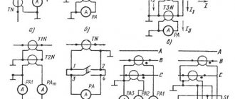
Current
Most often used to connect circuits on which measuring and recording devices (electricity meters, ammeters) and protective relays are installed.
Pulse
Converts the received signal into a rectangular pulse. Used to prevent high frequency interference.
Power
The design, most often, consists of several secondary windings that convert an incoming electrical impulse with one voltage system into several outgoing ones with other parameters of the voltage system.
Peak transformers
Used to convert the sinusoidal voltage component. The main purpose is to prevent interference in circuits with digitizing equipment.
Some sources list portable isolators as a separate category. It should be noted that the overall dimensions in the technical design of devices of various types do not play a key role.
Conditions for connecting and operating isolation transformers
Equipment that complies with GOST 15543.1 and GOST 15150 standards is intended for operation in moderate and cold climates. Depending on the type of housing and purpose, it can be installed in closed spaces with natural air exchange and without artificial regulation of the internal microclimate, as well as outdoors under a canopy or in a dry, unheated room where there is free access to outside air.
For different categories of installations, the corresponding temperature conditions have been determined: for standard units from -25ºС to +40ºС, for frost-resistant devices - from -60ºС to +40ºС. To effectively remove the heat generated during operation of the isolation transformer and ensure natural cooling, it should be installed on a frame or on wheels.
To avoid mechanical stress, all busbars and wires must be secured. The distance from the windings of the isolation transformer to the wall or other grounded structure should be 300 mm. Preventive maintenance work on voltage distributors is carried out twice a year. They include operations to clean the windings, magnetic circuit system and cooling channels from dirt, dust and foreign particles.
In addition, during service maintenance, the reliability of bolted connections must be tested, for which torque wrenches and wet cleaning of the windings with a sponge soaked in a solvent or alcohol solution are used. The volumes and frequency of each type of operation directly depend on operating conditions. It is also recommended to carry out a visual inspection of the equipment from time to time.
Read more:
- Separation transformer for 220/220 volts
- Medical isolation transformers
Isolating transformer (decoupling transformer)
Design features
Different types of isolation transformers can be either stationary or portable. Most often, portable devices have additional protection from external influences and are used in extreme operating conditions, in open areas.
Automatic transformers are not isolation transformers, since their design uses a different principle of arrangement of the primary and secondary windings.
They are combined into one, which forms, in addition to electromagnetic, a direct electrical connection. RTs for narrowly targeted use are being developed. For example, for hospitals and laboratories.
So-called medical isolation transformers are used to provide power supply with precisely defined parameters to sensitive devices installed in intensive care units, operating rooms of various biological, chemical and medical laboratories.
Material on the topic: interesting information about step-down transformers.
Features of operation
When operating a separating type household protective device, some energy will be lost. Different models are characterized by an efficiency of 70-85%. You won't be able to save on electricity bills. This feature is neglected. Safety and health of users are the most important factor when deciding to install protective equipment.
It is recommended to install the equipment inside basements or cable wells. Separating structures must be used in wet rooms when working with tools of safety class I.
There are universal and specialized models. For example, medical institutions install special types of structures. They ensure stable, safe operation of electrical devices in inpatient departments and operating rooms.
In order for the equipment to work long and reliably, it must be installed in a sealed, dry place. Dust and dirt should not seep inside. Therefore, before connecting, it is recommended to mount a box under it. It can be hung on the wall or attached to the floor.
The use of a transformer will minimize the risk of electric shock. The presence of a network protective device will extend the life of electrical appliances. Often the use of such units is extremely necessary.
Purpose of household transformer separators
Design of a medical isolation transformer.
A cardinal solution in terms of ensuring electrical safety in rooms such as bathrooms or basements is to prohibit the installation of sockets in them that connect directly to the power supply network.
In this case, an isolation transformer (IT) is installed near the outlet, the task of which is not to convert the voltage up or down, but only to isolate the device using mains electricity from the network itself.
For the purpose of safe use of the same outlet in the bathroom, the RT is powered by its primary winding from a 220 V power network, and its secondary winding is connected to the outlet. In this way, galvanic isolation of the power supply system and the device of use is carried out. The principle of operation of the RT is illustrated by a schematic diagram of its connection and devices for use.
It is prohibited to ground the secondary winding of the RT and connected devices! Only the casing (housing) of the transformer is grounded.
Connecting an isolation transformer to a heating boiler
Before connecting, you need to turn off the power supply. Now you need to decouple the galvanic circuit and for this you can use a transformer. Safety equipment should have a voltage threshold of 10-15%. Now you need to connect your devices. During operation, you can also connect the device to the neutral wire.
The first check can be performed after the first heating. When reconnecting to the network, you must wait until the system has completely cooled down.
Application of transformer separators
Design of an isolation transformer.
The design of the isolation transformer is made in complete analogy with the layout of the main functional elements in voltage converters of a step-up or step-down type of operation.
Also, primary and secondary windings with identical winding characteristics are installed on the magnetic circuit; according to the same laws of electromagnetic induction, alternating current electricity is converted from the primary winding to the secondary.
Since the voltage parameters of the output circuit repeat the same characteristics of the mains voltage applied to the primary, the voltage vectors in the circuits are practically the same.
The main design difference between RT and other transformers is the careful electrical insulation of the windings from each other. The connection between them is only magnetic due to the magnetic flux in the magnetic circuit.
It will be interesting➡ Idle mode for transformers
This method of transferring energy between circuits without direct electrical contact is called galvanic isolation. In this case, the secondary circuit of the transformer is not grounded! A sudden electrical breakdown will not cause an overcurrent; the leakage current in the event of accidental contact of a person with equipment under load will not exceed dangerous threshold values.
What does transformer galvanic isolation mean?
There are a large number of circuits used in electronics and electrical engineering that require the isolation or separation of high power voltages from low voltage control circuits. This creates a kind of protection for low-voltage devices from the influence of high voltage. That is, in such circuits there is no longer the flow of ordinary electric current. In such cases, in the absence of current, a large ohmic resistance arises between the devices, causing an open circuit.
This problem is successfully solved by galvanic isolation, which removes the galvanic connection between devices. Thus, energy or signals will be transferred from one circuit to another without any electrical contact between them. The use of galvanic isolation allows for contactless control and provides reliable protection of people and equipment from electric shock.
Transformer (inductive) isolation
In order to build inductive isolation, you should use magnetic induction devices - transformers. Its design can be cored or coreless. Equipping circuits with galvanic isolation of the inductive type is carried out using transformers whose transformation ratio is unity. The primary coil is connected to the signal source, and the secondary coil is connected to the receiver. On this principle, transformer-type galvanic isolations serve as the basis for the creation of magnetic modulation devices.
The output voltage arising in the secondary winding is directly related to the voltage at the input of the transformer device. In this regard, inductive isolation has serious disadvantages, which is why its use is limited:
- It is impossible to manufacture a compact device due to the significant overall dimensions of the transformer.
- The transmission frequency is limited by the frequency modulation of the isolation itself.
- Noise occurring in the input signal reduces the quality of the output signal.
- Such transformer galvanic isolation can only operate normally in the presence of alternating voltage.
There are also others:
- optoelectronic isolation;
- diode optocoupler;
- decoupling transistor optocoupler,
Read also:
- How to make an isolation transformer yourself from a TS-250 network transformer
- Isolation transformers for medical institutions
- Isolating transformer connection and operating conditions
Device characteristics
At its core, an isolation transformer resembles a step-down transformer of an ordinary electrical device, consisting of a primary and one (several) secondary windings. The turns of the primary windings of such transformers are separated by galvanic insulation from the secondary ones, however, in the event of emergency situations, for example, overheating, destruction of insulation or short circuit of the windings, the appearance of a phase in the secondary circuits could not be excluded. The main characteristics of isolation transformers are shown in the figure below.
Main technical characteristics of isolation transformers.
Isolating transformers have a transformation ratio equal to unity, provided by windings with identical parameters. And its main feature is the reliable galvanic separation of the windings.
This is realized by using reinforced or double insulation; the most reliable option is considered to be the decoupling of the primary and secondary windings by winding on different coils mounted on a single magnetic core. The efficiency of isolation transformers approaches 85%, but this is a worthy price to pay for electrical safety; it is not for nothing that such devices are called safety transformers.
The likelihood of suffering from secondary voltages in a network operating from an isolation transformer is minimized. Of course, the danger of electric shock remains if you touch both wires of the network (the concept of zero or phase in this circuit is not applicable), but each individually is neutral with respect to the ground and therefore does not pose a danger to human life.
An industrial isolation transformer in a housing is a complete panel structure with a transformer (or several transformers), an input switch, circuit breakers, a network indicator, and a terminal block for connecting a cable.
The galvanic isolation created by the RT between the incoming power system and the consumer load circuit provides reliable protection for users at home and maintenance personnel in production. The model range includes as basic designs:
- single-phase isolation transformer;
- three-phase dry isolation transformer.
Which model to choose for installation in your apartment or in a separate building is already chosen by the homeowner in accordance with the recommendations of experts. Transformers are produced for various types of voltage. Among others, the most common typical combinations are:
- isolation transformer input 380/220V – output 380/220V
- isolation transformer input 380/220V – output 220/127V
- isolation transformer input 220V – output 220V
- isolation transformer input 220V – output 36V
- isolation transformer input 220V – output 24V
- isolation transformer input 220V – output 12V
Tables 1 and 2 show the main characteristics of three-phase isolation transformers 380/380V and 380/220V and single-phase isolation transformers 220-220V.
Table 1. Main characteristics of three-phase isolation transformers 380/380V and 380/220V.
Table 2. Characteristics of single-phase isolation transformers 220-220V.
Winding connection diagrams for three-phase transformers in input/output combinations:
- star
- triangle
- zigzag
During operation of the transformer, a situation may arise where the thermal switch is triggered when the temperature of the transformer exceeds 125 degrees C. In this case, the transformer is turned off. This situation can occur when the transformer is overloaded or the input network voltage is exceeded. With proper operation, the transformer resumes operation after approximately 20 minutes.
How to burn $10,000 in one move and get electrocuted
Let's imagine a fairly ordinary situation: your mains power supply has broken down. You pick up a multimeter and measure the voltage at the input and output of the source. At the input you have an honest 230 V AC from the outlet, and at the output there are zeros. You know that your power supply is switching, and you are aware that the transistors of the source are controlled by a PWM controller, which is very easily identified on the board. You have a brand new Tektronix DPO 7254 oscilloscope or some LeCroy WavePro 7300A costing more than $10,000 on your desk, and you decide to use it to look at the PWM controller signals in order to diagnose its serviceability or malfunction. It is written on the oscilloscope probe that its maximum permissible voltage is 1000 V, which is by a good margin greater than the voltage in the outlet. Directly on the oscilloscope itself, next to the connectors for connecting the probes, the number 400 V is written, in addition, you have a probe with a divider of 1:100, which also gives you confidence that everything will be fine. You turn on the oscilloscope and try to connect its probe to the power supply board, however, as soon as you touch the oscilloscope probe to the power supply board, a spark jumps and a loud bang is heard. The screen of your brand new oscilloscope goes blank, the oscilloscope itself does not respond to any buttons, and the room is filled with the characteristic smell of burnt electronics. What happened? Why did the oscilloscope burn out and how to avoid it? Read about all this under the cut.
Denial of responsibility
This article addresses issues related to mains voltage, which can pose a threat to human life and health, as well as the performance of devices. All information in this article is provided for informational purposes only. You use the information provided at your own risk. In no event shall the author be liable for any direct, indirect, special or other consequential damages resulting from any use of the information in this article.
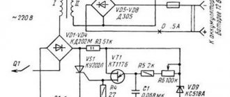
Power supply structure
In this section, of course, we will not consider in detail the design of pulse converters; this is a topic for a whole series of articles. We will consider this issue to the minimum extent necessary to understand the topic of the article. So, the figure below shows essentially the block diagram of a simple flyback converter. The flyback converter is chosen here solely as an example; it doesn’t matter what topology the power supply is (forward, bridge, half-bridge, push-pull or even a ballast capacitor), everything said is true for any of them.
It does not show common-mode and differential-mode filters, protection circuits and some other components, but this is not necessary to consider our question. In the diagram we see a diode bridge to which mains voltage is supplied, a PWM controller chip combined with a power transistor, a transformer and a feedback circuit. The mains voltage is rectified by a diode bridge: the plus is supplied to the transformer and switched by a power transistor, and the minus forms the local (power) ground potential. The PWM controller is powered relative to this potential, the feedback voltage is measured, and control voltages are also applied relative to it to the gates of the power transistor (which in this circuit is located inside the controller). If we want to measure some voltage on the primary side, this must also be done relative to this potential. In general, this is a classic GND, with the exception of one nuance: it is not galvanically isolated from the network (it has a direct connection with the phase and neutral through a pair of diodes). And it is precisely this nuance that is decisive, but more on that later.
Oscilloscope structure
This section will consider the issue of galvanic coupling both between the oscilloscope channels themselves and between the oscilloscope channels and the ground line. There are two types of oscilloscopes: with isolated channels and without such isolation. Oscilloscopes with isolated channels are a rather rare type of device, and this fact will be emphasized in the description of the device. If you've never wondered whether your oscilloscope has this kind of isolation, it probably doesn't. What does this mean in practice? This means that the resistance between the ground tail of the oscilloscope probe and the ground pin in the 230 V power outlet is close to zero. For better understanding, this fact is demonstrated in the figure below.
This figure shows the resistance measurement between the ground tail of the oscilloscope probe and the ground pin of the oscilloscope power cord.
As you can see, the resistance value is very small and is only 2.18 Ohms. In reality, it is even less, because the resistance of the multimeter probes themselves, which can be more than 1 Ohm, was not taken into account. So, let's make an important conclusion: in an oscilloscope, the ground tail of the probe is connected to the ground contact of the socket and through it is grounded in the electrical panel.
Structure of a 230 V household network
The most complete description of the structure of a 230 V network, of course, is best found in some literature on the theory of electrical circuits, by reading the section on three-phase circuits.
Within the framework of this article, only a very small part of this course will be presented, which is directly related to our problem. A regular household outlet usually comes with 3 wires: phase, neutral and ground. In old Soviet-built houses there may not be a third wire (grounding). The ground wire is, in general, true to its name: it eventually goes into a bus (ground loop), which is buried deep in the ground somewhere under the building or in the immediate vicinity of it (of course, not just anyhow, but in accordance with certain rules). This wire is designed to protect a person from possible electric shock: in the event of an emergency, for example, voltage comes into contact with the device body, the current begins to flow through the grounding wire, which leads to the activation of the automatic protection system and the voltage being cut off.
Neutral is essentially very close to grounding. If you look closely at a power line in a rural area, you will notice that the neutral conductor is grounded at each pole.
In addition, the neutral conductor is also grounded at the substation (there are some nuances here, but in everyday life this is usually the case; we do not consider circuits with an isolated neutral).
In an ideal world, the resistance between the ground wire and the neutral in the socket is zero, and they are at exactly the same potential. In the real world, the resistance of conductors makes its own adjustments, and between the neutral and grounding there is a resistance of the order of several tens of ohms. Let's remember this fact; it will be useful to us in the future.
The phase conductor is the “working” conductor itself, which forms a sinusoid relative to the neutral. The sine wave in a household outlet has an amplitude of about 325 V and fluctuates plus and minus relative to the neutral conductor. Thus, with a positive half-wave of a sine wave, the current flows from the phase conductor to the neutral one, and with a negative half-wave, on the contrary, the current flows from the neutral conductor to the phase one.
What happens when you connect an oscilloscope?
So, let’s summarize the conclusions from the previous sections of the article:
- In a network switching power supply, the local (power) ground circuit is connected to the neutral and phase through diodes.
- In an oscilloscope, the ground tail of the probe is connected inside it to the ground contact of the socket.
- The resistance between the neutral and grounding in the network is small and amounts to a few to tens of ohms.
- With a positive half-wave of a sinusoid, current flows from the phase conductor to the neutral one, and with a negative half-wave, from the neutral to the phase conductor.
In order to understand how currents will flow when connecting an oscilloscope to the primary side of a switching power supply, it is best to use simulation.
Recently I usually use LTSpice as a modeling environment, so we will conduct the analysis in it. We will model exclusively the input circuits of the converter: now there is no need to include a transformer and other wiring in the model, because they do not affect the topic of the article in any way. I even excluded the storage capacitor after the diode bridge from the model, so that the transient process during its charging would not distract from the subject of the simulation. First, let's see how the circuit behaves without a connected oscilloscope. The figure below shows the results of modeling such a circuit (picture clickable).
Resistance R1 in this case is the load resistance. I chose it to be 100 kOhm. You can take any other, in this case its size is not important. Resistance R2 is the resistance between neutral and conductor and ground. I chose it to be 10 ohms. The amplitude voltage between phase and neutral is 325 V, which corresponds to an effective voltage value of 230 V, the signal is shown in the green graph.
As can be seen from the current graphs, it nowhere exceeds a few milliamps and the entire system feels good.
What happens if you connect an oscilloscope to such a circuit? The result is shown in the figure below (the picture is clickable).
As you can see, resistor R3 with a resistance of 2 Ohms has been added to the model. This resistor matches the resistance between the ground tail of the oscilloscope probe and the ground pin of the oscilloscope's power cord. A little higher, we measured this parameter and obtained a value equal to about 2 ohms. This resistor is connected to the local power ground PGND: this is where you will most likely connect the oscilloscope ground if you want to make measurements on the primary side of the power supply. But how does the current behave in this case? And it grows to catastrophic levels. The current in our model is more than 25 A! In this case, the current is limited by the resistance between neutral and ground, the internal resistance of the diode bridge, as well as the resistance of all wires. And this current flows, among other things, through resistor R3, i.e. through the oscilloscope probe and through its internal circuits. 25 And through the internal circuits of the oscilloscope, they are guaranteed to burn out everything that is possible inside; it is not even a fact that the printed circuit board itself will survive. Thus, this picture very clearly shows what will happen to the device if you just try to measure signals on a source that is not disconnected from the network.
If we analyze the results above a little, it becomes clear that the negative half-wave of a sine wave in the socket is fatal for an oscilloscope. The negative half-wave creates a negative potential at the point between diodes D1 and D3. A zero potential (GND) is applied to the PGND point through the tail of the oscilloscope probe, which is connected inside it to the ground of the socket. Thus, we form a potential difference, and diode D1 turns on in direct polarity, which leads to a sharp increase in current. All of the above is clearly illustrated in the figure below.
What about the RCD?
Indeed, when the ground tail of the oscilloscope is connected to the local (power) ground, a current imbalance occurs on the mains voltage side and this must be handled by the RCD. Perhaps it will save the oscilloscope circuits from complete burnout, however, alas, the RCD does not operate instantly; its response time is tens of milliseconds. During this time, at least one half-wave of the mains voltage sinusoid will have time to slip through, which, if it does not completely burn out the device, will most likely still damage the sensitive input circuits of the oscilloscope. In addition, the RCD is not always present in the electrical panel. Therefore, although an RCD is certainly a useful component of electrical wiring, in this case it is unwise to rely on it to protect the device. But what if you still need to look at some signals from a device operating on a 230 V network? In fact, there are several ways this can be done relatively safely, more on that in the next section.
How to look at the signals on the mains voltage side and not burn the devices?
1. Use an oscilloscope with galvanically isolated channels.
In an oscilloscope with galvanically isolated channels, all channels are isolated both from each other and from ground. Thus, when connecting the device to the circuit, we will not have a circuit through which a short circuit and burnout of the circuit can occur. However, be extremely careful, even if you have an oscilloscope with isolated channels. Carefully study the documentation for your device and pay attention to the specific figures for the maximum permissible voltage relative to ground. If you analyze signals on the mains voltage side, then most likely you will need special high-voltage probes that allow you to carry out measurements at high potential. Using an oscilloscope with decoupled channels has one big drawback - price. Such oscilloscopes are noticeably more expensive than oscilloscopes with similar characteristics, the grounds of which channels are connected on a common chassis. In addition, the range of such oscilloscopes is quite meager compared to classic oscilloscopes, of course. Overall, if you have an isolated-channel oscilloscope and know how to use it, chances are you didn't learn much new from this article.
2. Use a differential probe
If you do not have an oscilloscope with galvanically isolated channels, but have a regular one, then you can isolate any of its channels using a special device called a differential probe. An example of such a device is shown in the figure below.
With this device it is possible to view signals on the mains voltage side relatively safely. There are quite a large number of types of similar devices for different input voltages and frequencies with different input voltage division ratios. As a rule, these are active devices that require additional power, for example, the device in the figure above requires a 9 V adapter. The price of such devices is usually also not very affordable and amounts to tens and sometimes hundreds of thousands of rubles (at the exchange rate at the time of writing).
3. Use an isolation transformer
A completely working way to protect the oscilloscope and at the same time view the signals on the mains voltage side is to use an isolating transformer with a transformation ratio of 1:1 (i.e., the voltage value at the output of the transformer is equal to the voltage value at its input). Through such a transformer it is necessary to connect the object of study (for example, the same power source we are analyzing). An explanatory picture with the simulation results is shown below (the picture is clickable).
As we can see, despite the fact that the grounded tail of the oscilloscope probe is connected to the circuit in exactly the same way, there are no prohibitive values on the current graphs. The current through the inside of the oscilloscope (through resistance R3) is zero, and the amplitude of the current of the power supply and load is several milliamps, as we had with the oscilloscope not connected. This happens because we now have the PGND ground galvanically isolated from the mains voltage. However, this does not mean at all that now everything is safe for humans: the output of the transformer is still 230 V of effective voltage, which can pose a mortal danger.
When using an isolation transformer, in addition to the transformation ratio, it is also necessary to look at such a parameter as the maximum permissible power. Obviously, the power consumed by your load should not exceed the maximum permissible power that the transformer is designed to handle. Thus, this method is unlikely to be suitable for analyzing installations of several kilowatts: the dimensions and weight of the required transformer will be too large.
4. Use a laboratory power supply
If your object of study is a switching power supply, then you can safely view its primary circuits by powering it not from a 230 V network, but through a laboratory DC power supply. There is always a transformer inside such a power source, thus galvanic isolation is achieved, and the oscilloscope can be safely connected to the circuit being analyzed. Since there is a rectifier at the input of the switching power supply, there is no big difference for its operation whether you supply a sinusoid or a constant voltage to the input. Of course, the value of this DC voltage must correspond to the rectified mains voltage with some tolerance. In our previous work, we used the B5-50 source as such a power source; it is shown in the figure below.
It doesn’t look very modern, but it can produce an output voltage of up to 300 V and is well suited for debugging circuits with a power of up to a couple of hundred watts.
An additional very big plus of using a laboratory power supply when debugging is that you can set the required current limit on the power supply. This way, even if the circuit is faulty, you won't have a loud bang and most likely nothing will burn out. This approach is incomparably better than the well-known connection of a circuit through an incandescent light bulb. The only thing worth remembering is that the power of the laboratory power supply must be sufficient to power the circuit under study.
5. Use an outlet without grounding
Attention! This method is classified as dangerous, so I cannot recommend using it.
However, to complete the picture, I must tell you about it, if only to inform about possible dangers. Moreover, it happens that it often turns out to be the only possible way to view the signal on the mains voltage side without using any special equipment such as an isolation transformer or an oscilloscope with isolated channels. This method involves plugging the oscilloscope into a socket without a ground terminal (see the figure below).
This destroys the current flow path, but this leads to one big problem.
Now the oscilloscope ground is at a deadly potential. This means that life-threatening voltage will be present on all BNC connectors of the oscilloscope, on the ground tails of all connected probes, and also, possibly, on the housings of all other devices plugged into the same socket (if the socket is still there are grounding contacts, but there is no grounding wire connected to it). And if now you just touch the coaxial connector on the oscilloscope body with one hand, and with the other, conditionally, grab the battery... well, you understand. It is completely unacceptable to use this method if you have an oscilloscope in a metal case. If you still use this method, then disconnect all unnecessary probes, as well as other wires (USB, RS-232, etc.), make sure that only one oscilloscope is plugged into the outlet, make all connections, configure all the knobs on the oscilloscope in advance, Make sure that you do not accidentally touch the BNC connectors and only then apply mains voltage. However, if all precautions are taken, this method generally works. Below the spoiler is an oscillogram of the voltage from the outlet, taken by me back in my student years using this very method. Since the mains voltage has a range that exceeds the number of cells on the oscillograph screen, the measurement took place through a resistive voltage divider of 1:5.
Socket voltage
6. Use a battery-powered oscilloscope
Some oscilloscopes can be powered by built-in rechargeable batteries. The power cord is not connected; therefore, the oscilloscope is not grounded. In essence, this method is a complete analogue of the previous one, only instead of an ungrounded socket, the oscilloscope is powered from the built-in battery. This method is absolutely as dangerous as the previous one: the same deadly potential will be present on all connectors of the oscilloscope, therefore all the safety measures described in the previous paragraph of the article are equally valid for this method.
7. Power the control chips with low voltage from a laboratory source
Sometimes there are situations when high mains voltage is not necessary for debugging. In this case, it is better to simply power the control circuits using a low-voltage laboratory power supply. The required voltage is always specified in the documentation for specific microcircuits (for example, in the case of studying a PWM controller, it usually does not exceed 20 V). In this case, the 230 V mains voltage is not supplied, of course, so it is absolutely safe to use an oscilloscope to examine the pulses at the controller output, the operation of the oscillator, the value of the reference voltages and other critical signals. Of course, without the presence of mains voltage it will not be possible to check everything, but a frankly dead controller can be diagnosed without problems.
General recommendations for working with mains voltage
1. When working with mains voltage, always follow safety precautions
Yes, this has already been written about everywhere a hundred times, but, nevertheless, for some reason, what not to do is often found out only through personal experience. You should not climb into live devices during operation; it is better to complete all connections before turning on the power. Don’t forget about storage capacitors: their discharge takes some time, which can tend to infinity (conditionally, of course), if the developer has not installed discharge resistors.
2. Read the instructions for your device
Of course, life is too short to read instructions, so they are usually only opened when something doesn't work or is broken. But if you work with mains voltage, it’s still worth looking in advance to see what the actual limit numbers are for your device. Negligence in this matter can be very costly.
3. Use inexpensive appliances
If you are researching mains voltage, then put aside your cool Tectronix DPO 7254, which costs several million, and take some Nantek DSO 5102 for a couple of tens of thousands of rubles. On the mains voltage side, you don't need gigasamples and fancy math, but if something goes wrong, the error won't cost that much.
4. If possible, always work with galvanic isolation from the mains
Due to non-compliance with this rule, a lot of electronics have already burned out in this world. In my practice, there was a case that cost me a laptop and a JTAG debugger. I was debugging one device and there seemed to be no signs of trouble. The device had a metal case and a neon light was installed on the case, which glowed from a 230 V network. The case, naturally, was grounded. The board itself with the microcontroller was powered from a separate isolated power source. And at one fine moment this light bulb made its way onto the body of the device. At this moment, a JTAG debugger was connected to the board, which was plugged into the laptop. The laptop, in turn, was plugged into a grounded outlet. Thus, the current flowed along the chain “neon light bulb - case - board - JTAG debugger - laptop - laptop power supply - grounding.” Of course, the laptop and programmer burned out beyond repair. This could have been avoided if a galvanically isolated JTAG debugger had been used. Well, of course, it’s also not worth using a top-end MacBook Pro as a work machine when debugging power electronics (see the previous paragraph).
Conclusion
The things described in the article may seem simple, obvious and on the surface. However, unfortunately, I personally have more than once seen oscilloscopes burn out for the stated reason, and not from green guys, but from developers who have been in the industry for many years. If this article allows you to protect at least one oscilloscope from this, then I will already consider that I wrote it not in vain.
Advantages and scope
Isolating transformers are widely used in almost all areas of electrical engineering. They provide the user with a wide range of specific benefits depending on the industry in which they are used:
- devices with a transformation ratio of 1:1 are used in AC power networks without the need for additional grounding and insulation of peripheral equipment;
- isolation of DC circuits in communication lines. If it is necessary to use signal amplifiers, the use of RT makes it possible to separate the direct current for connecting the amplifier from the components of the information electrical pulse;
- increasing the safety of electrical equipment operation. Minimizes the risk of fatal electrical shock by isolating the user or operator from high-power sources;
- when testing, servicing or repairing equipment, it makes it possible to carry out work on devices that are turned on. In this case, isolation transformers are used with a ratio of 1:1, but having a low voltage power of the secondary circuit;
- filter out (cut off outside the operating range) the distorted sinusoidal voltage waveform, bringing it to the correct one. Reduce the negative impact of pulse width modulations;
- neutralizes a wide range of noise generated when connecting audio devices (amplifiers) to speakers.
It will be interesting➡ Necessary conditions for parallel operation of transformers
The use of isolation transformers is determined by the operational requirements and specific application of electrical networks:
- High humidity or the presence of water in the room, the presence of metal products without grounding or with weak grounding: bathrooms and shower rooms, power switching cabinets located on the street, cable wells, basements and semi-basements.
- Remote tracking, measurement and control posts in medical institutions, data and call centers, as well as other institutions where it is necessary to increase the level of personnel protection and the safety of equipment operation.
- Operation of power tools and equipment belonging to the first safety class.
Installation of operation of electrical appliances through an isolation transformer is necessary in the following cases:
- when connecting power consumption devices that do not have grounding potential;
- in pulsed power networks that require increased insulation performance. Especially in medical and laboratory equipment;
- during laboratory testing of electrical and electronic devices to ensure personnel safety.
When using an isolation transformer, it is also necessary to use a residual current device (RCD) for the operated circuit. Despite the high reliability and safety, cases of insulation damage are possible.
In this case, the potential can be brought to the body of the device and there is a possibility of electric shock if you touch the body and the metal conductor connected to the ground. That is why it is recommended to connect isolation transformers through an RCD. A single-phase isolation transformer, depending on its design, can be used in the following cases:
- With mounting plates and exposed terminal blocks. Installation in an installation cabinet. In this case, a vertical or horizontal installation scheme or special fasteners for mounting on a DIN rail can be implemented.
- If there are no terminal blocks, remove the secondary winding through a cable branch. It is used as a component of electrical equipment and installations for any purpose.
- Portable option with a housing, socket and switch. Additionally, it can be equipped with a cable (extension cord).
A three-phase isolation transformer is actually three single-phase devices installed on one mounting plate:
- open option in both horizontal and vertical arrangement with star or triangle connection;
- arrangement of elements in the housing, including sealed housing.
- An isolation transformer is a necessary and useful device, especially in a home workshop. It can be used in reduced AC voltage mode to test high voltage devices.
Three-phase isolation transformers.
For example, connecting a 220 V circuit to a 36 V power source will allow you to safely monitor the flow of current in the tested circuits.
In this case, the use of any unified isolation transformers is allowed, since modern electronic devices do not have high consumption.
Useful to know: how to assemble a step-up transformer yourself.
How to make your own isolation transformer
It is not difficult to make a low-power device yourself, if you have similar skills and basic knowledge in the field of electrical engineering.
Sequence of operations:
- two half windings are made on two identical cores - the coils are divided in half;
- a pair of half windings are connected in series;
- Additionally, you can equip the device with a throttle or stabilizer.
A more detailed diagram of the device and the order of connecting the half-windings is shown in the diagram:
The device can be used to power a workshop or other auxiliary room. Before connecting to a stationary power supply, the device must be tested with a small electric current. An ordinary low-power lamp is suitable as a consuming device.
But if the home handyman does not have enough electrical knowledge and no experience in such work, it is recommended to contact a specialist of the appropriate profile.
Examples of using
The use of isolation transformers is mandatory in high-risk areas. A typical example is the bathroom, where the use of conventional electrical power is limited:
- high air humidity;
- the possibility of water getting into live parts;
- the presence of metal objects with unstable grounding.
When carrying out temporary work in particularly hazardous areas, the use of portable safety transformers is allowed. Thanks to the medical isolation transformer, it becomes possible to create special IT networks that are required for powering Group 2 premises (intensive care units, operating rooms), completely safe for both patients and medical personnel.
The rated power of single-phase transformers for such networks can range from 0.5 to 10 kW. If necessary, three-phase isolation transformers are used. The video provides information about a self-assembled isolation transformer.
Connection method
A typical circuit looks like this: the primary winding is connected to the electrical network through a residual current device (RCD), which prevents current leakage.
The device requiring protection is connected to the secondary winding, forming an insulated circuit. It, as well as the consumer housing, must not be grounded. Other devices can be connected directly to the primary circuit through a residual current device. Grounding of their housings is allowed. Thus, with the help of isolation transformers, it is possible to supply power to those places where the use of a conventional electrical network may be unsafe. This does not invalidate the basic safety rules. For example, you should not intentionally touch the terminals themselves. The same current flows through them as in the primary circuit, which can cause serious electrical injury. Installation of isolation transformers must be carried out by qualified specialists.
Device
An industrial or household transformer 220 to 220 volts is called a switchgear. It is used for houses and apartments. The design has two windings. The secondary coil is not grounded. This principle allows you to avoid electric shock when touching the winding or wires coming from the unit.
The device minimizes the risk of electric shock to the user. Its possibility cannot be completely ruled out. If a person touches the connected secondary winding and a metal object (ground) at the same time, a short circuit will occur.
The coils of the device have additional insulation. They don't touch each other. This allows the secondary coil to operate autonomously.
Isolation transformer design
Windings are wound around the magnetic core, between which there are at least two layers of reinforced insulation.
An option with a special protective screen installed in addition to the main insulation is also possible. The number of turns, as well as the thickness of the mounting wire, will be the same. It is then that the transformation coefficient becomes equal to unity. Thanks to the reinforced insulation and the interwinding screen, galvanic isolation is created, and the consumer is completely separated from the ground . There are also other types of isolation transformers:
- step-down for powering flashlights;
- automatic;
- pulse;
- peak;
- measuring;
- high frequency;
- power.