The conversion of electrical energy into kinetic energy is carried out using various types of electric motors. Most often, electric motors serve as electric drives for machines and mechanisms and are used to ensure the operation of pumping equipment, ventilation systems and many other units and devices. In connection with such a wide application, the calculation of electric motor power is of particular relevance. For these purposes, many different methods have been developed that allow calculations to be performed in relation to specific operating conditions.
Main types of electric motors
There are many types and modifications of electric motors. Each of them has its own power and other parameters.
The main classification divides these devices into DC and AC motors. The first option is used much less frequently, since its operation requires the presence of a direct current source or a device that converts alternating voltage into direct current. Fulfilling this condition in modern production will require significant additional costs.
But, despite significant disadvantages, DC motors have a high starting torque and operate stably even at high overloads. Due to their qualities, these units are widely used in electric transport, in the metallurgical and machine tool industries.
However, most modern equipment runs on AC motors. The operation of these devices is based on electromagnetic induction, which is created in a magnetic field by a conducting medium. The magnetic field is created using windings flowing around currents or using permanent magnets. Electric motors operating on alternating current can be synchronous or asynchronous.
The use of synchronous electric motors is practiced in equipment where a constant rotation speed is required. These are DC generators, pumps, compressors and other similar installations. Different models differ in their own technical characteristics. For example, the rotation speed can be in the range of 125-1000 rpm, and the power reaches 10 thousand kilowatts.
Many designs have a short-circuited winding located on the rotor. With its help, if necessary, an asynchronous start is made, after which the synchronous motor continues to operate as usual, minimizing electrical energy losses. These engines are characterized by their small size and high efficiency.
Asynchronous AC motors have become much more widespread in the manufacturing sector. They are characterized by a very high frequency of rotation of the magnetic field, significantly exceeding the speed of rotation of the rotor. A significant disadvantage of these devices is considered to be a decrease in efficiency to 30-50% of the norm at low loads. In addition, during start-up, the current parameters become several times greater compared to operating indicators. These problems are eliminated by using frequency converters and soft starters.
Asynchronous motors are used in those facilities where frequent switching on and off of equipment is required, for example, in elevators, winches, and other devices.
How to determine the power of an electric motor?
In order to perform the calculation, you will need measuring tools and reference information. So, there are options for determining the power of an electric motor:
- by current . We supply power to the asynchronous electric motor. We alternately measure the current in each coil with an ammeter. As a result, the average current value is multiplied by the voltage and the power consumption of the electric motor is obtained;
- by size . We measure the diameter and length of the stator core. Let's find out the shaft speed. Next, we make an approximate calculation of the “constant” using the formula:
3.14•D•n/(120•f).
Based on the calculation, we find a constant in the reference book. We calculate
P = C•D²•l•n•10^(-6);
- by traction force . We measure the speed of rotation of the shaft using a tachometer, the radius of the shaft with a regular ruler, and the traction force of the engine with a dynamometer. To calculate, we multiply all the found values
P = M • w = F •2•3.14• n • r .
Based on these mathematical expressions, we can conclude that asynchronous motors can have the same power, but differ in shaft speed, which significantly affects its dimensions. Let's also consider the meaning of using power regulators.
Calculation of engine power formula for compressor
When choosing an electric motor that is most suitable for the operation of a particular compressor, it is necessary to take into account the long-term operation of this mechanism and the constant load. The required power of the RDV engine is calculated in accordance with the power on the shaft of the main mechanism. In this case, the losses arising in the intermediate link of the mechanical transmission should be taken into account.
Additional factors are the capacity, purpose and nature of the production where the compressor equipment will be operated. They have an impact and the equipment may require minor but ongoing adjustments to maintain proper performance.
Designations of the main mounting and connecting dimensions of motors
Legend for overall dimensions:
- h is the height of rotation of the shaft or the size of the electric motor. Height from the center of the shaft axis to the ground. Important connection size when assembling the unit and aligning it
- l30*h31*d24 - length, height, width of the AIR electric motor, dimensions. Necessary for calculating the cost of delivery and the required space during transportation
- m is the weight of the electric motor, mass. Needed to calculate transport costs and strength of materials
- d1 - shaft diameter. Overall connection size of the AIR required when aggregating with other equipment or selecting a coupling half
- d20 - width, mounting diameter of the flange. d22 is the diameter of the flange holes. Overall dimensions for manufacturing or selecting a counter flange
- l10 and b10 – the distance between the mounting holes on the motor feet. Important overall and installation dimensions required when mounting the electric motor to a frame or platform
- L1 – shaft length
- b1 – key width. The size required for the manufacture of the coupling half
Mounting design – flange, feet, combined
Connection and dimensional drawing of the installation design of the AIR electric motor on feet (IM 1081), feet-flange (IM 2081), clean flange (IM 3081).
Calculation formula for fans
Fans are widely used in a variety of fields. General purpose devices operate in clean air, at temperatures below 80. Air with a higher temperature is moved using special heat-resistant fans. If you have to work in an aggressive or explosive environment, in these cases models of anti-corrosion and explosion-proof devices are used.
In accordance with the principle of operation, fan units can be centrifugal or radial and axial. Depending on the design, they develop pressure from 1000 to 15000 Pa. Therefore, the power required to drive the fan is calculated in accordance with the pressure that needs to be created.
For this purpose, the formula is used: Nв=Hв·Qв/1000·efficiency, in which Nв is the power required for the drive (kW), Hв is the pressure created by the fan (Pa), Qв is the moved volume of air (m3/s), efficiency – efficiency factor.
To calculate the power of the electric motor, the formula is used :, where the parameter values will be as follows:
- Q – unit productivity;
- Н – outlet pressure;
- ηв – fan efficiency;
- ηп – transmission efficiency;
- short – safety factor depending on the power of the electric motor. With a power of up to 1 kW, short circuit = 2; from 1 to 2 kW short circuit = 1.5; at 5 kW and above short circuit = 1.1-1.2.
This formula allows you to calculate the power of electric motors for centrifugal and axial fans. For centrifugal structures, the efficiency is 0.4-0.7, and for axial ones - 0.5-0.85. Other design characteristics are available in special catalogs for all types of electric motors.
The power reserve should not be too large. If it is too large, the efficiency of the drive will noticeably decrease. In addition, AC motors may experience a reduction in power factor.
What is a three-phase network in electricity
The multiphase AC electrical network was created thanks to the American scientist N. Tesla. In Russia, scientist M. Dolivo-Dobrovolsky developed and promoted the widespread implementation of a three-phase electrical network.
Connecting source and consumers
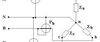
Three phases of alternating current are supplied, which are equal in amplitude and shifted relative to each other by 120°. The phases can be connected to each other in several ways. The most common of them are “star” and “triangle”.
In the first case, they have one common wire. With this use case, it becomes possible to supply line or phase voltage. In an apartment, the first is 380 V, the second is 220 V. The common wire is usually connected to ground, although there are connection diagrams in which this is not the case.
For your information! With a delta connection, each phase output is connected to one output of the other phase.
Three phase transmission line
Three-phase or single-phase connection
Depending on what type of connection is used, the power consumption is determined differently.
In a single-phase network, the energy consumed is calculated using the simplest formula:
where cosϕ is the power factor characterizing the phase shift between current and voltage in a reactive load.
The power of a 3-phase network is the sum of consumption for each phase separately. The power formula for 3-phase current is as follows:
Ptotal=Uа∙Iа∙cosϕа+ Ub∙Ib∙cosϕb+ Uc∙Ic∙cosϕc,
where U, I, cosϕ are voltage, current and power factor in each phase, respectively.
For your information. It can be seen that in the general case, a three-phase connection requires a larger number of metering devices.
Sometimes you can calculate energy consumption using a simplified version. With symmetrical consumption, for example, when connecting an asynchronous motor, the consumption currents are the same, and the formula takes the following form:
Where:
- Uph, Iph – phase voltage and current;
- Ul, Il – linear voltage and current.
Characteristics of a three-phase system
A three-phase power supply system is characterized by several voltage and current values. It all depends on between which points of the circuit the measurements are made:
- between the phase wire and the neutral – phase voltage Uph;
- between individual phases – linear Ul.
The relationship between these parameters:
With symmetrical load distribution, the currents in all wires are equal. In a four-wire circuit (with a grounded zero), there is no current in the neutral conductor, so even if the zero is broken, the network continues to function normally.
In the case where the energy consumption differs between phases, some current flows in the neutral wire. A complete break in the neutral conductor causes a phase imbalance, so the voltage on the wires can change in the range from zero to linear.
The reactive nature of the load is taken into account by the power factor cosϕ. This value comes from the theory of complex numbers, which are used when it is necessary to calculate the parameters of alternating current circuits. In the case of an active load, cosϕ = 1, but the more reactive the consumers are, the more the coefficient decreases, showing how the real power decreases relative to the total.
Important! Therefore, to correctly calculate and reduce the load on generating equipment, power factor correctors are installed in reactive circuits. Circuits with a corrector bring the cosϕ coefficient closer to unity.
Selecting the rating of the circuit breaker
Applying the formula I = P/209, we find that with a load with a power of 1 kW, the current in a single-phase network will be 4.78 A. The voltage in our networks is not always exactly 220 V, so it would not be a big mistake to calculate the current strength with a small margin like 5 A for every kilowatt of load. It is immediately clear that it is not recommended to connect an iron with a power of 1.5 kW to an extension cord marked “5 A”, since the current will be one and a half times higher than the rated value. You can also immediately “graduate” the standard ratings of the machines and determine what load they are designed for:
- 6 A – 1.2 kW;
- 8 A – 1.6 kW;
- 10 A – 2 kW;
- 16 A – 3.2 kW;
- 20 A – 4 kW;
- 25 A – 5 kW;
- 32 A – 6.4 kW;
- 40 A – 8 kW;
- 50 A – 10 kW;
- 63 A – 12.6 kW;
- 80 A – 16 kW;
- 100 A – 20 kW.
Using the “5 amperes per kilowatt” technique, you can estimate the current strength that appears in the network when connecting household devices. You are interested in peak loads on the network, so for the calculation you should use the maximum power consumption, not the average. This information is contained in the product documentation. It is hardly worth calculating this indicator yourself by summing up the rated powers of the compressors, electric motors and heating elements included in the device, since there is also such an indicator as the efficiency factor, which will have to be assessed speculatively with the risk of making a big mistake.
When designing electrical wiring in an apartment or country house, the composition and passport data of the electrical equipment that will be connected are not always known for certain, but you can use the approximate data of electrical appliances common in our everyday life:
- electric sauna (12 kW) – 60 A;
- electric stove (10 kW) – 50 A;
- hob (8 kW) – 40 A;
- instantaneous electric water heater (6 kW) – 30 A;
- dishwasher (2.5 kW) - 12.5 A;
- washing machine (2.5 kW) - 12.5 A;
- Jacuzzi (2.5 kW) – 12.5 A;
- air conditioner (2.4 kW) – 12 A;
- Microwave oven (2.2 kW) – 11 A;
- storage electric water heater (2 kW) – 10 A;
- electric kettle (1.8 kW) – 9 A;
- iron (1.6 kW) – 8 A;
- solarium (1.5 kW) – 7.5 A;
- vacuum cleaner (1.4 kW) – 7 A;
- meat grinder (1.1 kW) – 5.5 A;
- toaster (1 kW) – 5 A;
- coffee maker (1 kW) – 5 A;
- hair dryer (1 kW) – 5 A;
- desktop computer (0.5 kW) – 2.5 A;
- refrigerator (0.4 kW) – 2 A.
The power consumption of lighting devices and consumer electronics is small; in general, the total power of lighting devices can be estimated at 1.5 kW and a 10 A circuit breaker is sufficient for a lighting group. Consumer electronics are connected to the same outlets as irons; it is not practical to reserve additional power for them.
If you sum up all these currents, the figure turns out to be impressive. In practice, the possibility of connecting the load is limited by the amount of allocated electrical power; for apartments with an electric stove in modern houses it is 10 -12 kW and at the apartment input there is a machine with a nominal value of 50 A. And these 12 kW must be distributed, taking into account the fact that the most powerful consumers concentrated in the kitchen and bathroom. Wiring will cause less cause for concern if it is divided into a sufficient number of groups, each with its own machine. For the electric stove (hob), a separate input with a 40 A automatic circuit breaker is made and a power outlet with a rated current of 40 A is installed; nothing else needs to be connected there. A separate group is made for the washing machine and other bathroom equipment, with a machine of the appropriate rating. This group is usually protected by an RCD with a rated current 15% greater than the rating of the circuit breaker. Separate groups are allocated for lighting and for wall sockets in each room.
Determination of shaft speed
Three-phase asynchronous motors are divided into 4 types based on rotor speed: 3000, 1500, 1000 and 750 rpm. min. Here is an example of marking based on AIR 180:
- AIR 180 M2 – where 2 is 3000 rpm.
- AIR 180 M4 - 4 is 1500 rpm. min.
- AIR 180 M6 – 6 indicates a rotation speed of 1000 rpm.
- AIR 180 M8 - 8 means that the output shaft rotation speed is 750 rpm.
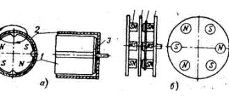
The easiest way to determine the number of revolutions of a three-phase asynchronous electric motor is to remove the rear casing and look at the stator winding.
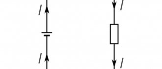
For a 3000 rpm engine, the stator winding coil occupies half a circle - 180 °, that is, the beginning and end of the section are parallel to each other and perpendicular to the center. For electric motors at 1500 rpm the angle is 120°, at 1000 rpm it is 90°. A schematic view of the coils is shown in the drawing. See the table for all motor winding data.
Find out the rotation speed using an ammeter
You can find out the motor shaft speed by counting the number of poles. To do this, we need a milliammeter - we connect the measuring device to the stator winding. When the motor shaft rotates, the ammeter needle will deviate. The number of needle deflections per revolution is equal to the number of poles.
- 2 poles – 3000 rpm
- 4 poles – 1500 rpm
- 6 poles – 2000 rpm
- 8 poles – 750 rpm
Measuring power with a wattmeter
The power consumption of three-phase current is measured using wattmeters. This can be a special wattmeter for a 3-phase network, or a single-phase one connected according to a specific circuit. Modern electricity metering devices are often made using digital circuitry. Such designs are characterized by high measurement accuracy and greater capabilities for operating with input and output data.
Measurement options:
- Star connection with neutral conductor and symmetrical load - the measuring device is connected to one of the lines, the readings taken are multiplied by three.
- Asymmetrical current consumption in a star connection - three wattmeters in the circuit of each phase. The wattmeter readings are summed up;
- Any load and delta connection - two wattmeters connected in a circuit of any two loads. The wattmeter readings are also summed up.
In practice, they always try to make the load symmetrical. This, firstly, improves network parameters, and secondly, simplifies the accounting of electrical energy.
Electric motor AIR characteristics
| engine's type | R, kW | Rated rotation speed, rpm | efficiency,* | COS f | 1p/1n | Mn/Mn | Mmax/Mn | 1n, A | Weight, kg |
| Buy AIR56A2 | 0,18 | 2840 | 68,0 | 0,78 | 5,0 | 2,2 | 2,2 | 0,52 | 3,4 |
| Buy AIR56V2 | 0,25 | 2840 | 68,0 | 0,698 | 5,0 | 2,2 | 2,2 | 0,52 | 3,9 |
| Buy AIR56A4 | 0,12 | 1390 | 63,0 | 0,66 | 5,0 | 2,1 | 2,2 | 0,44 | 3,4 |
| Buy AIR56V4 | 0,18 | 1390 | 64,0 | 0,68 | 5,0 | 2,1 | 2,2 | 0,65 | 3,9 |
| Buy AIR63A2 | 0,37 | 2840 | 72,0 | 0,86 | 5,0 | 2,2 | 2,2 | 0,91 | 4,7 |
| Buy AIR63V2 | 0,55 | 2840 | 75,0 | 0,85 | 5,0 | 2,2 | 2,3 | 1,31 | 5,5 |
| Buy AIR63A4 | 0,25 | 1390 | 68,0 | 0,67 | 5,0 | 2,1 | 2,2 | 0,83 | 4,7 |
| Buy AIR63V4 | 0,37 | 1390 | 68,0 | 0,7 | 5,0 | 2,1 | 2,2 | 1,18 | 5,6 |
| Buy AIR63A6 | 0,18 | 880 | 56,0 | 0,62 | 4,0 | 1,9 | 2 | 0,79 | 4,6 |
| Buy AIR63V6 | 0,25 | 880 | 59,0 | 0,62 | 4,0 | 1,9 | 2 | 1,04 | 5,4 |
| Buy AIR71A2 | 0,75 | 2840 | 75,0 | 0,83 | 6,1 | 2,2 | 2,3 | 1,77 | 8,7 |
| Buy AIR71V2 | 1,1 | 2840 | 76,2 | 0,84 | 6,9 | 2,2 | 2,3 | 2,6 | 10,5 |
| Buy AIR71A4 | 0,55 | 1390 | 71,0 | 0,75 | 5,2 | 2,4 | 2,3 | 1,57 | 8,4 |
| Buy AIR71V4 | 0,75 | 1390 | 73,0 | 0,76 | 6,0 | 2,3 | 2,3 | 2,05 | 10 |
| Buy AIR71A6 | 0,37 | 880 | 62,0 | 0,70 | 4,7 | 1,9 | 2,0 | 1,3 | 8,4 |
| Buy AIR71V6 | 0,55 | 880 | 65,0 | 0,72 | 4,7 | 1,9 | 2,1 | 1,8 | 10 |
| Buy AIR71A8 | 0,25 | 645 | 54,0 | 0,61 | 4,7 | 1,8 | 1,9 | 1,1 | 9 |
| Buy AIR71V8 | 0,25 | 645 | 54,0 | 0,61 | 4,7 | 1,8 | 1,9 | 1,1 | 9 |
| Buy AIR80A2 | 1,5 | 2850 | 78,5 | 0,84 | 7,0 | 2,2 | 2,3 | 3,46 | 13 |
| Buy AIR80A2ZHU2 | 1,5 | 2850 | 78,5 | 0,84 | 7,0 | 2,2 | 2,3 | 3,46 | 13 |
| Buy AIR80V2 | 2,2 | 2855 | 81,0 | 0,85 | 7,0 | 2,2 | 2,3 | 4,85 | 15 |
| Buy AIR80V2ZHU2 | 2,2 | 2855 | 81,0 | 0,85 | 7,0 | 2,2 | 2,3 | 4,85 | 15 |
| Buy AIR80A4 | 1,1 | 1390 | 76,2 | 0,77 | 6,0 | 2,3 | 2,3 | 2,85 | 14 |
| Buy AIR80V4 | 1,5 | 1400 | 78,5 | 0,78 | 6,0 | 2,3 | 2,3 | 3,72 | 16 |
| Buy AIR80A6 | 0,75 | 905 | 69,0 | 0,72 | 5,3 | 2,0 | 2,1 | 2,3 | 14 |
| Buy AIR80V6 | 1,1 | 905 | 72,0 | 0,73 | 5,5 | 2,0 | 2,1 | 3,2 | 16 |
| Buy AIR80A8 | 0,37 | 675 | 62,0 | 0,61 | 4,0 | 1,8 | 1,9 | 1,49 | 15 |
| Buy AIR80V8 | 0,55 | 680 | 63,0 | 0,61 | 4,0 | 1,8 | 2,0 | 2,17 | 18 |
| Buy AIR90L2 | 3,0 | 2860 | 82,6 | 0,87 | 7,5 | 2,2 | 2,3 | 6,34 | 17 |
| Buy AIR90L2ZHU2 | 3,0 | 2860 | 82,6 | 0,87 | 7,5 | 2,2 | 2,3 | 6,34 | 17 |
| Buy AIR90L4 | 2,2 | 1410 | 80,0 | 0,81 | 7,0 | 2,3 | 2,3 | 5,1 | 17 |
| Buy AIR90L6 | 1,5 | 920 | 76,0 | 0,75 | 5,5 | 2,0 | 2,1 | 4,0 | 18 |
| Buy AIR90LA8 | 0,75 | 680 | 70,0 | 0,67 | 4,0 | 1,8 | 2,0 | 2,43 | 23 |
| Buy AIR90LB8 | 1,1 | 680 | 72,0 | 0,69 | 5,0 | 1,8 | 2,0 | 3,36 | 28 |
| Buy AIR100S2 | 4,0 | 2880 | 84,2 | 0,88 | 7,5 | 2,2 | 2,3 | 8,2 | 20,5 |
| Buy AIR100S2ZHU2 | 4,0 | 2880 | 84,2 | 0,88 | 7,5 | 2,2 | 2,3 | 8,2 | 20,5 |
| Buy AIR100L2 | 5,5 | 2900 | 85,7 | 0,88 | 7,5 | 2,2 | 2,3 | 11,1 | 28 |
| Buy AIR100L2ZHU2 | 5,5 | 2900 | 85,7 | 0,88 | 7,5 | 2,2 | 2,3 | 11,1 | 28 |
| Buy AIR100S4 | 3,0 | 1410 | 82,6 | 0,82 | 7,0 | 2,3 | 2,3 | 6,8 | 21 |
| Buy AIR100L4 | 4,0 | 1435 | 84,2 | 0,82 | 7,0 | 2,3 | 2,3 | 8,8 | 37 |
| Buy AIR100L6 | 2,2 | 935 | 79,0 | 0,76 | 6,5 | 2,0 | 2,1 | 5,6 | 33,5 |
| Buy AIR100L8 | 1,5 | 690 | 74,0 | 0,70 | 5,0 | 1,8 | 2,0 | 4,4 | 33,5 |
| Buy AIR112M2 | 7,5 | 2895 | 87,0 | 0,88 | 7,5 | 2,2 | 2,3 | 14,9 | 49 |
| Buy AIR112M2ZHU2 | 7,5 | 2895 | 87,0 | 0,88 | 7,5 | 2,2 | 2,3 | 14,9 | 49 |
| Buy AIR112M4 | 5,5 | 1440 | 85,7 | 0,83 | 7,0 | 2,3 | 2,3 | 11,7 | 45 |
| Buy AIR112MA6 | 3,0 | 960 | 81,0 | 0,73 | 6,5 | 2,1 | 2,1 | 7,4 | 41 |
| Buy AIR112MB6 | 4,0 | 860 | 82,0 | 0,76 | 6,5 | 2,1 | 2,1 | 9,75 | 50 |
| Buy AIR112MA8 | 2,2 | 710 | 79,0 | 0,71 | 6,0 | 1,8 | 2,0 | 6,0 | 46 |
| Buy AIR112MB8 | 3,0 | 710 | 80,0 | 0,73 | 6,0 | 1,8 | 2,0 | 7,8 | 53 |
| Buy AIR132M2 | 11 | 2900 | 88,4 | 0,89 | 7,5 | 2,2 | 2,3 | 21,2 | 54 |
| Buy AIR132M2ZHU2 | 11 | 2900 | 88,4 | 0,89 | 7,5 | 2,2 | 2,3 | 21,2 | 54 |
| Buy AIR132S4 | 7,5 | 1460 | 87,0 | 0,84 | 7,0 | 2,3 | 2,3 | 15,6 | 52 |
| Buy AIR132M4 | 11 | 1450 | 88,4 | 0,84 | 7,0 | 2,2 | 2,3 | 22,5 | 60 |
| Buy AIR132S6 | 5,5 | 960 | 84,0 | 0,77 | 6,5 | 2,1 | 2,1 | 12,9 | 56 |
| Buy AIR132M6 | 7,5 | 970 | 86,0 | 0,77 | 6,5 | 2,0 | 2,1 | 17,2 | 61 |
| Buy AIR132S8 | 4,0 | 720 | 81,0 | 0,73 | 6,0 | 1,9 | 2,0 | 10,3 | 70 |
| Buy AIR132M8 | 5,5 | 720 | 83,0 | 0,74 | 6,0 | 1,9 | 2,0 | 13,6 | 86 |
| Buy AIR160S2 | 15 | 2930 | 89,4 | 0,89 | 7,5 | 2,2 | 2,3 | 28,6 | 116 |
| Buy AIR160S2ZHU2 | 15 | 2930 | 89,4 | 0,89 | 7,5 | 2,2 | 2,3 | 28,6 | 116 |
| Buy AIR160M2 | 18,5 | 2930 | 90,0 | 0,90 | 7,5 | 2,0 | 2,3 | 34,7 | 130 |
| Buy AIR160M2ZHU2 | 18,5 | 2930 | 90,0 | 0,90 | 7,5 | 2,0 | 2,3 | 34,7 | 130 |
| Buy AIR160S4 | 15 | 1460 | 89,4 | 0,85 | 7,5 | 2,2 | 2,3 | 30,0 | 125 |
| Buy AIR160S4ZHU2 | 15 | 1460 | 89,4 | 0,85 | 7,5 | 2,2 | 2,3 | 30,0 | 125 |
| Buy AIR160M4 | 18,5 | 1470 | 90,0 | 0,86 | 7,5 | 2,2 | 2,3 | 36,3 | 142 |
| Buy AIR160S6 | 11 | 970 | 87,5 | 0,78 | 6,5 | 2,0 | 2,1 | 24,5 | 125 |
| Buy AIR160M6 | 15 | 970 | 89,0 | 0,81 | 7,0 | 2,0 | 2,1 | 31,6 | 155 |
| Buy AIR160S8 | 7,5 | 720 | 85,5 | 0,75 | 6,0 | 1,9 | 2,0 | 17,8 | 125 |
| Buy AIR160M8 | 11 | 730 | 87,5 | 0,75 | 6,5 | 2,0 | 2,0 | 25,5 | 150 |
| Buy AIR180S2 | 22 | 2940 | 90,5 | 0,90 | 7,5 | 2,0 | 2,3 | 41,0 | 150 |
| Buy AIR180S2ZHU2 | 22 | 2940 | 90,5 | 0,90 | 7,5 | 2,0 | 2,3 | 41,0 | 150 |
| Buy AIR180M2 | 30 | 2950 | 91,4 | 0,90 | 7,5 | 2,0 | 2,3 | 55,4 | 170 |
| Buy AIR180M2ZHU2 | 30 | 2950 | 91,4 | 0,90 | 7,5 | 2,0 | 2,3 | 55,4 | 170 |
| Buy AIR180S4 | 22 | 1470 | 90,5 | 0,86 | 7,5 | 2,2 | 2,3 | 43,2 | 160 |
| Buy AIR180S4ZHU2 | 22 | 1470 | 90,5 | 0,86 | 7,5 | 2,2 | 2,3 | 43,2 | 160 |
| Buy AIR180M4 | 30 | 1470 | 91,4 | 0,86 | 7,2 | 2,2 | 2,3 | 57,6 | 190 |
| Buy AIR180M4ZHU2 | 30 | 1470 | 91,4 | 0,86 | 7,2 | 2,2 | 2,3 | 57,6 | 190 |
| Buy AIR180M6 | 18,5 | 980 | 90,0 | 0,81 | 7,0 | 2,1 | 2,1 | 38,6 | 160 |
| Buy AIR180M8 | 15 | 730 | 88,0 | 0,76 | 6,6 | 2,0 | 2,0 | 34,1 | 172 |
| Buy AIR200M2 | 37 | 2950 | 92,0 | 0,88 | 7,5 | 2,0 | 2,3 | 67,9 | 230 |
| Buy AIR200M2ZHU2 | 37 | 2950 | 92,0 | 0,88 | 7,5 | 2,0 | 2,3 | 67,9 | 230 |
| Buy AIR200L2 | 45 | 2960 | 92,5 | 0,90 | 7,5 | 2,0 | 2,3 | 82,1 | 255 |
| Buy AIR200L2ZHU2 | 45 | 2960 | 92,5 | 0,90 | 7,5 | 2,0 | 2,3 | 82,1 | 255 |
| Buy AIR200M4 | 37 | 1475 | 92,0 | 0,87 | 7,2 | 2,2 | 2,3 | 70,2 | 230 |
| Buy AIR200L4 | 45 | 1475 | 92,5 | 0,87 | 7,2 | 2,2 | 2,3 | 84,9 | 260 |
| Buy AIR200M6 | 22 | 980 | 90,0 | 0,83 | 7,0 | 2,0 | 2,1 | 44,7 | 195 |
| Buy AIR200L6 | 30 | 980 | 91,5 | 0,84 | 7,0 | 2,0 | 2,1 | 59,3 | 225 |
| Buy AIR200M8 | 18,5 | 730 | 90,0 | 0,76 | 6,6 | 1,9 | 2,0 | 41,1 | 210 |
| Buy AIR200L8 | 22 | 730 | 90,5 | 0,78 | 6,6 | 1,9 | 2,0 | 48,9 | 225 |
| Buy AIR225M2 | 55 | 2970 | 93,0 | 0,90 | 7,5 | 2,0 | 2,3 | 100 | 320 |
| Buy AIR225M4 | 55 | 1480 | 93,0 | 0,87 | 7,2 | 2,2 | 2,3 | 103 | 325 |
| Buy AIR225M6 | 37 | 980 | 92,0 | 0,86 | 7,0 | 2,1 | 2,1 | 71,0 | 360 |
| Buy AIR225M8 | 30 | 735 | 91,0 | 0,79 | 6,5 | 1,9 | 2,0 | 63 | 360 |
| Buy AIR250S2 | 75 | 2975 | 93,6 | 0,90 | 7,0 | 2,0 | 2,3 | 135 | 450 |
| Buy AIR250M2 | 90 | 2975 | 93,9 | 0,91 | 7,1 | 2,0 | 2,3 | 160 | 530 |
| Buy AIR250S4 | 75 | 1480 | 93,6 | 0,88 | 6,8 | 2,2 | 2,3 | 138,3 | 450 |
| Buy AIR250M4 | 90 | 1480 | 93,9 | 0,88 | 6,8 | 2,2 | 2,3 | 165,5 | 495 |
| Buy AIR250S6 | 45 | 980 | 92,5 | 0,86 | 7,0 | 2,1 | 2,0 | 86,0 | 465 |
| Buy AIR250M6 | 55 | 980 | 92,8 | 0,86 | 7,0 | 2,1 | 2,0 | 104 | 520 |
| Buy AIR250S8 | 37 | 740 | 91,5 | 0,79 | 6,6 | 1,9 | 2,0 | 78 | 465 |
| Buy AIR250M8 | 45 | 740 | 92,0 | 0,79 | 6,6 | 1,9 | 2,0 | 94 | 520 |
| Buy AIR280S2 | 110 | 2975 | 94,0 | 0,91 | 7,1 | 1,8 | 2,2 | 195 | 650 |
| Buy AIR280M2 | 132 | 2975 | 94,5 | 0,91 | 7,1 | 1,8 | 2,2 | 233 | 700 |
| Buy AIR280S4 | 110 | 1480 | 94,5 | 0,88 | 6,9 | 2,1 | 2,2 | 201 | 650 |
| Buy AIR280M4 | 132 | 1480 | 94,8 | 0,88 | 6,9 | 2,1 | 2,2 | 240 | 700 |
| Buy AIR280S6 | 75 | 985 | 93,5 | 0,86 | 6,7 | 2,0 | 2,0 | 142 | 690 |
| Buy AIR280M6 | 90 | 985 | 93,8 | 0,86 | 6,7 | 2,0 | 2,0 | 169 | 800 |
| Buy AIR280S8 | 55 | 740 | 92,8 | 0,81 | 6,6 | 1,8 | 2,0 | 111 | 690 |
| Buy AIR280M8 | 75 | 740 | 93,5 | 0,81 | 6,2 | 1,8 | 2,0 | 150 | 800 |
| Buy AIR315S2 | 160 | 2975 | 94,6 | 0,92 | 7,1 | 1,8 | 2,2 | 279 | 1170 |
| Buy AIR315M2 | 200 | 2975 | 94,8 | 0,92 | 7,1 | 1,8 | 2,2 | 248 | 1460 |
| Buy AIR315MV2 | 250 | 2975 | 94,8 | 0,92 | 7,1 | 1,8 | 2,2 | 248 | 1460 |
| Buy AIR315S4 | 160 | 1480 | 94,9 | 0,89 | 6,9 | 2,1 | 2,2 | 288 | 1000 |
| Buy AIR315M4 | 200 | 1480 | 94,9 | 0,89 | 6,9 | 2,1 | 2,2 | 360 | 1200 |
| Buy AIR315S6 | 110 | 985 | 94,0 | 0,86 | 6,7 | 2,0 | 2,0 | 207 | 880 |
| Buy AIR315M(A)6 | 132 | 985 | 94,2 | 0,87 | 6,7 | 2,0 | 2,0 | 245 | 1050 |
| Buy AIR315MV6 | 160 | 985 | 94,2 | 0,87 | 6,7 | 2,0 | 2,0 | 300 | 1200 |
| Buy AIR315S8 | 90 | 740 | 93,8 | 0,82 | 6,4 | 1,8 | 2,0 | 178 | 880 |
| Buy AIR315M(A)8 | 110 | 740 | 94,0 | 0,82 | 6,4 | 1,8 | 2,0 | 217 | 1050 |
| Buy AIR315MV8 | 132 | 740 | 94,0 | 0,82 | 6,4 | 1,8 | 2,0 | 260 | 1200 |
| Buy AIR355S2 | 250 | 2980 | 95,5 | 0,92 | 6,5 | 1.6 | 2,3 | 432,3 | 1700 |
| Buy AIR355M2 | 315 | 2980 | 95,6 | 0,92 | 7,1 | 1,6 | 2,2 | 544 | 1790 |
| Buy AIR355S4 | 250 | 1490 | 95,6 | 0,90 | 6,2 | 1,9 | 2,9 | 441 | 1700 |
| Buy AIR355M4 | 315 | 1480 | 95,6 | 0,90 | 6,9 | 2,1 | 2,2 | 556 | 1860 |
| Buy AIR355MA6 | 200 | 990 | 94,5 | 0,88 | 6,7 | 1,9 | 2,0 | 292 | 1550 |
| Buy AIR355S6 | 160 | 990 | 95,1 | 0,88 | 6,3 | 1,6 | 2,8 | 291 | 1550 |
| Buy AIR355MV6 | 250 | 990 | 94,9 | 0,88 | 6,7 | 1,9 | 2,0 | 454,8 | 1934 |
| Buy AIR355L6 | 315 | 990 | 94,5 | 0,88 | 6,7 | 1,9 | 2,0 | 457 | 1700 |
| Buy AIR355S8 | 132 | 740 | 94,3 | 0,82 | 6,4 | 1,9 | 2,7 | 259,4 | 1800 |
| Buy AIR355MA8 | 160 | 740 | 93,7 | 0,82 | 6,4 | 1,8 | 2,0 | 261 | 2000 |
| Buy AIR355MV8 | 200 | 740 | 94,2 | 0,82 | 6,4 | 1,8 | 2,0 | 315 | 2150 |
| Buy AIR355L8 | 132 | 740 | 94,5 | 0,82 | 6,4 | 1,8 | 2,0 | 387 | 2250 |
up
How to find out your scheme
To correctly determine and calculate power, knowledge of several factors is required:
- Number of power phases;
- Method of connecting consumers.
For a single-phase connection, two wires are used:
A three-phase network is characterized by the presence of three or four conductors (connection with a grounded neutral). In this case, two different switching schemes are used:
- "Triangle". Each load is connected to two adjacent ones. The voltage of each phase is supplied to the consumer connection points.
- "Star". All three consumers are connected at one point. The power phases are connected to the second ends. This is an isolated neutral circuit. In a circuit with a grounded neutral, the consumer connection point is connected to the neutral conductor.