The widespread use of the asynchronous electric motor (IM) is due to its reliability and simplicity of design. The stator of such a motor is standard; it is a hollow cylinder made of electrostatic steel plates with a three-phase winding. The rotor can be squirrel-cage and phase. The latter option has become more widespread for a number of reasons, although its design is much more complex than that of a squirrel-cage rotor.
Wound rotor design
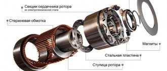
The phase rotor of the IM is structurally similar to its stator. The rotor base is made of electrostatic steel plates, which are mounted on the shaft. The design has longitudinal grooves into which the turns of the phase winding coils are placed. The number of rotor phases strictly corresponds to the number of stator phases. To connect the rotor winding to the circuit, 3 slip rings are installed on the latter’s shaft, to which the ends of the winding are connected, which are in contact with the conductive brushes. In turn, the brushes have outlets into the housing box, which will allow you to connect external additional resistance.
Depending on the network voltage, the winding phases are connected in a “triangle” or “star”. The axes of the coils of a two-pole electric motor are shifted 120 degrees relative to each other.
Slip rings are made of brass or steel. They are mounted on the shaft with mandatory insulation between each other. The brushes are located on a brush holder, made of metalgraphite, and pressed against the rings by means of springs.
Types of electromechanical devices
Stator - concept and principle of operation
The rotor is used in electromechanical devices such as motors operating on direct and alternating electric current and generators.
AC units
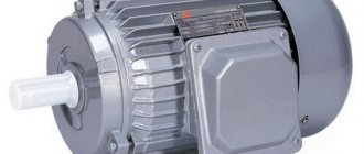
These units include various electric motors. The most common model of this device consists of the following parts:
- Aluminum or cast iron ribbed housing with a mounting box for connecting the stator and rotor windings;
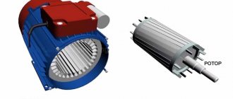
- The stator is a stationary part in the form of a hollow cylinder located inside the housing. The stator winding consists of 3 pairs of coils of insulated copper wire located opposite each other, wound in the grooves of the housing
- An all-metal cylindrical rotor with a shaft and grooves into which highly conductive aluminum rods are soldered.
AC powered motor
The rotor rotates on two support bearings pressed onto its shaft. Cooling of an electric motor operating at high speeds occurs thanks to the impeller - a small fan consisting of many blades and located at one end of the rotor shaft. The ribbed structure of the aluminum housing also contributes to effective cooling of the operating unit.
The operating principle of such an engine is as follows:
- When current is connected to the unit, it alternately passes through one of three pairs of stator coils.
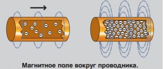
- When electric current flows through pairs of stator coils, they create a magnetic field, the lines of force of which intersect the rotor.
- Alternately powered pairs of coils create a moving magnetic field, which, according to the law of electromagnetic induction, provokes the appearance of an electric current in the stationary metal rods of the rotor.
- The induced current in the rotor results in a force that pushes it out of the stator's magnetic field. Since the frequency of current supply to the stator coils is on average about 30 pulses per second, the buoyant force that appears in the rotor leads to its rotation at high speed.
Important! Depending on the simultaneity of the rotation of the rotor and the magnetic field generating this movement, an alternating current electric motor can be synchronous (the rotor of the unit rotates synchronously with the magnetic field of the stator) and asynchronous (the rotation of the armature is not synchronized with the movement of the magnetic field of the stator). The first type is characterized by high power and reliability, while the second is characterized by a wide variety of designs and applications.
DC machines
The most common brushed DC motor is an electrical unit consisting of:
- Cast iron body with cooling fins and a special mounting box for connecting the unit windings;
- Shaft made of durable tool steel with two bearings;
- An armature consisting of a core (a set of plates made of special electrical steel), an armature winding (coils of copper wire placed in the grooves of the core);
- An inductor consisting of excitation poles with coils of copper wire wound on them;
- Collector - copper plates located on the shaft, to which the leads of the armature winding coils are connected;
- Spring-loaded graphite or metal-graphite brushes (brush group).
Such an engine is cooled, like its analogue operating on alternating current, by an impeller located on the shaft.
DC motor
Important! Unlike an AC electric motor, the rotor speed in such a power unit is controlled by a special unit, which, using a Hall sensor mounted on the shaft, determines the position of the rotor and its speed.
A similar unit works as follows:
- Voltage is applied to the field winding, thereby creating a constant magnetic field;
- Through the brushes and commutator, voltage is supplied to the coils of the armature core - the magnetic field that arises is repelled from the same one formed by the inductor, as a result of which the engine begins to rotate (“starts”);
- Subsequently, when rotating, the remaining coils of the armature winding are energized through the brushes, which leads to uniform rotation of the armature at a certain speed.
The rotation of such a unit is stopped by stopping the supply of voltage to the brush group.
In addition to the electric motors described above, machines operating on direct current also include a rotary starter - a device necessary for starting gasoline and diesel internal combustion automobile engines.
Why do you need additional resistance?
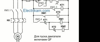
Additional resistance serves to start the engine with a load on its shaft. As soon as the nominal shaft speed is reached, the resistance is turned off as unnecessary, and the rings are short-circuited. Otherwise, the operation of the electric motor will be unstable and there will be a loss of efficiency.
The role of additional external resistance, as a rule, is performed by a step rheostat. In this case, the engine will also accelerate in steps. Devices are often used that can increase the efficiency of the motor, while relieving the brushes of excessive friction on the rings. After acceleration, the device raises the brushes and closes the rings.
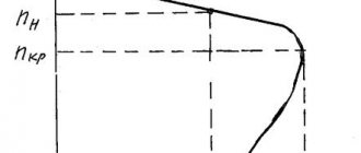
To implement automatic starting of the electric motor, an inductance connected to the rotor winding is used. The fact is that at the moment when the start is carried out, the inductance and current frequency in the rotor are maximum. As the engine accelerates, these indicators drop, and eventually the engine returns to normal operating mode.
Principle of operation
The stator electromagnets are located close to the rotor bars and transmit electricity to them to rotate it. The magnetic field induced in the rotor will follow the magnetic field of the stator, thereby performing mechanical rotation of the rotor shaft and associated units. At the same time, the electromagnetic induction created by the stator coils pushes the current on the rods strictly away from itself. The value of the current in the rods changes with time.
Write comments, additions to the article, maybe I missed something. Take a look at the site map, I will be glad if you find anything else useful on my site. All the best.
The difference between a squirrel-cage rotor and a phase rotor
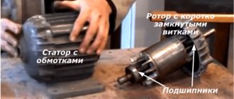
In a squirrel-cage motor rotor, unlike the phase version, there are no windings. They are replaced by rods closed at the ends with rings made of aluminum or copper. Visually, the design of such a rotor resembles a squirrel wheel, which is where it got its name - “squirrel cage”.
The squirrel-cage rotor is driven into rotation by inducing current by the magnetic field of the stator. To eliminate the pulsation of the magnetic field in the rotor, the rods of the “squirrel cage” are located parallel to each other, but at an angle relative to the axis of rotation. IMs with a squirrel-cage rotor are highly reliable due to the absence of brushes, which fray over time. In addition, their cost is less than that of variants with a wound rotor.
Asynchronous motor rotor: design
Rotor is an element of an electric motor rotating inside the stator (stationary component), the shaft of which is connected to parts of working units, for example, saws, turbines and pumps. The laminated core is made from individual electrical steel plates with semi-closed or open grooves.
The massive rotor is a solid steel cylinder placed inside the stator, with a core pressed onto its surface.
The non-contact rotor winding, not connected to any external electrical circuit, creates torque and is of two types:
- squirrel-cage (squirrel-cage rotor);
- phase (wound rotor).
Advantages and disadvantages of an electric motor with a wound rotor
IMs with phase-wound rotors have become widespread due to a number of serious advantages over other machines of this kind. Among them, it is worth noting the high starting torque, as well as the relatively constant rotation speed even under high loads. Such electric motors require less starting current to start, and the design allows the use of automatic starting devices. In addition, these electric machines can withstand prolonged overloads well.
Like any electrical mechanism, wound-rotor electric motors have a number of disadvantages:
- Sensitivity to voltage changes;
- Large overall dimensions
- High price;;
- More complex design due to the rotor circuit with additional resistance;
- Lower power factor and efficiency indicators (relative to IM with a squirrel-cage rotor).
Single-phase asynchronous electric motors
Device and principle of operation
The power of such a single-phase 220V motor can, depending on the design, range from 5 W to 10 kW. Its rotor is usually a short-circuited winding (“squirrel cage”) - copper or aluminum rods closed at the ends.
Such a single-phase motor usually has two windings offset by 90° relative to each other. The working (main) one occupies most of the stator slots, and the starting (auxiliary) one occupies the remaining part. And it is called single-phase because it has only one working winding.
Alternating current flowing through the main winding creates a periodically changing magnetic field. It can be considered to consist of two circular ones with the same amplitude, rotating towards each other.
According to the law of electromagnetic induction, in closed turns of the rotor, a changing magnetic flux creates an induced current that interacts with the field that generates it. If the rotor is stationary, the moments of the forces acting on it are the same, as a result of which the rotor remains stationary.
If the rotor begins to rotate, then the equality of the moments of these forces will be violated, since the sliding of its turns relative to the rotating magnetic fields will become different. As a consequence, the Ampere force acting on the rotor turns from the direct magnetic field will be significantly greater than from the reverse one.
An induced current in the rotor turns can only arise when they cross the magnetic field lines. And to do this, they must rotate at a speed slightly lower than the field rotation frequency (with one pair of poles - 3000 rpm). Hence the name that such electric motors received, asynchronous.
As the mechanical load increases, the rotation speed decreases and the magnitude of the induction current in the rotor turns increases. As a result, both the mechanical power of the engine and the power of the alternating current it consumes increase.
Startup and connection diagram
It is clear that it is inconvenient to manually spin the rotor every time you start the electric motor. The starting winding is used to create the initial starting torque. Since it makes a right angle with the working winding, in order to create a rotating magnetic field, the current in it must be shifted in phase relative to the current in the working winding by also 90°.
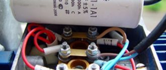
This can be achieved by including a phase-shifting element in its power supply circuit. A resistor or inductor cannot provide a phase shift of 90°, so in most situations it is logical to use a capacitor as a phase-shifting element. In this case, a single-phase electric motor has the best starting properties.
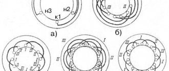
When the phase-shifting element is a capacitor, single-phase electric motors can be structurally as follows:
- with a starting capacitor (Fig. a);
- with starting and working (Fig. b);
- only with a working capacitor (Fig. c).
The first (most common) option involves connecting the starting winding with a capacitor for a short time during the start-up, after which they are turned off. It can be implemented using a time relay, or even simply by closing the circuit while pressing the start button. This starting circuit is characterized by a relatively small starting current, but in rated mode the characteristics are low. The reason is that the stator field is elliptical (it is stronger in the pole direction than in the perpendicular direction).
A circuit with a working, always-on capacitor works better in nominal mode, but has mediocre starting characteristics. The option with a starting and running capacitor is intermediate between the two described above. Calculating the values of their capacitances is relatively simple: for the working one 0.75 μF per 1 kW of power, for the starting one - 2.5 times more.
Scope of application of electric motors with wound rotor
Due to their high torque, low starting currents and the ability to operate for a long time at high loads, motors with a wound rotor are used where high electric motor power is needed, but there is no need to smoothly regulate the rotation speed over wide ranges. In addition, these machines are perfectly suited for starting with a load on the shaft.
Due to their high performance, wound rotor motors are most often used on various serious, heavy power equipment, for example, cranes, elevator drives, machine tools, and various lifts. In other words, these engines are used where there is a need to start under load, and not at idle.
Checking a wound rotor motor
As is known, electric motors with a wound rotor have windings on both the stator and the rotor, which increases the likelihood of failure of just one of them.
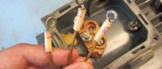
To check the stator windings of a three-phase IM for integrity, you need to get to their connection terminals. Then you need to measure the resistance between the phase terminals separately, having first removed the jumpers. If the resistance of any winding is less than that of others, this indicates a short circuit between its turns. In this case, the motor is rewinded.
To check the rotor windings, you need to find the leads from the slip rings. Then you need to make sure that the winding resistances match. If the design of the electric motor provides for a system for disconnecting the rotor windings, the lack of contact may be due to the breakdown of this mechanism, and not to the breakage of the turns.
The following factors may indicate the presence of any malfunction of the blood pressure:
- Reduced rotation speed under load. Characteristic of high resistance in the rotor circuit, weak contact in its winding, low mains voltage
- Deployment of the IM when the rotor circuit is open - short circuit in the rotor winding
- Excessive uniform increase in engine temperature - prolonged overload of the motor or its insufficient cooling
- Heating of the stator winding of a local nature - double short circuit of the stator coils to the housing or between phases, short circuit between turns, incorrect connection of coils in phase with each other
- Heating of the stator steel of a local nature - violation of the insulation between the steel sheets, their melting and burnout, short circuit
- Extraneous noise during AD operation. It can be caused by both bearing failure and insufficient pressing of active steel. Determined by ear by the nature of extraneous noise
- Burnout in the armature winding of the fuses, lack of contact in the supply wiring, failure of the rheostat
For self-diagnosis and correction of electric motor malfunctions, at least minimal knowledge of the design of blood pressure and electrical circuits in general is necessary. However, it is highly not recommended to repair an electric motor with a wound rotor yourself, as this can lead to electric shock.
Full diagnostic inspection of the engine
In order to inspect the stator and other central elements of the electric motor, special goats are used, equipped with two rollers in the upper part. The latter simplify the rotation of parts.
Self-repair of the motor should begin with a thorough study of all technical documentation. Next, the degree of wear of the bearings is determined, and other defects are detected and eliminated.
It is necessary to check the motor rotor for the condition of all metal elements, the attachment of the plates to the shaft, the quality of the closed wiring and, finally, the proper functioning of the fans.
Technical work is carried out using a set of special keys, an ordinary tester and lifting mechanisms. The main thing is not to forget to disconnect the motor from the network. All components are cleaned of dust layers using brushes and blown with compressed air. In the future, it is advisable to put small parts and all their fastenings in a separate box to avoid loss.
The electric motor rotor is disassembled taking into account the following recommendations. As soon as the shield is separated from the motor body, it is moved along the shaft, being careful not to damage the insulation of the windings. For these purposes, high-density cardboard is used, placing it between the stator and rotor, and subsequently laying parts on it.
Springs and bearings are also removed from the shaft. The short-circuited winding and core are dismantled. The main requirement when removing the rotor is careful movement along the axis.
When checking fans, pay attention to the integrity of the blades and the reliability of their fastening. The procedure is done using a hammer. Defective parts are replaced. The balancing must not be disturbed, so before inspection it is necessary to make a note on the rotor so that each element falls into place when assembled.