Why do you need a speed controller?
Typically, mini drills are built on the basis of conventional DC motors.
And the speed of such engines depends on the load and applied voltage. As a result, at idle speed the engine spins very strongly, and during drilling moments the engine speed fluctuates in a wide range. If you reduce the voltage on the motor when there is no load on it, you can achieve an increase in the service life of both the drills and the motors themselves. In addition, even drilling accuracy is improved. The easiest way to achieve this is to measure the current drawn by the motor.
There are many circuits of similar regulators on the Internet, but most of them use linear voltage regulators. They are massive and require cooling. In collaboration with TinyElectronicFriends, we wanted to make a compact board based on a switching stabilizer so that it could simply be “put on” the motor.
Typical tool failures
Knowing the design of an electric drill, it is easy to determine the reason why one or another of its functions does not work. It should be noted that you can avoid breakdowns of power tools if you periodically carry out preventive maintenance related to replacing the lubricant of mechanical parts.
After completing drilling work, it is necessary to remove dust from the tool, especially from its ventilation holes. The nature of faults is divided into electrical or mechanical origin.
Electrical damage
This type of breakdown occurs due to exceeding the permissible load on the device and violations in its operation. They manifest themselves in the refusal of the tool to turn on, in a malfunction of the reverse or speed controller. Most often, to restore functionality, you will need to disassemble the start button and clean all places associated with the electrical contact.
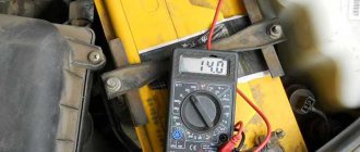
The appearance of a burning smell indicates an overload in the operation of the electric motor. In this case, the condition of the brushes and windings is first checked, and the connection points of the power wire are examined to ensure there are no burns. Burning is associated with the ingress of dust, as a result of which the contact resistance increases, which leads to heating. Electrical faults are easily calculated using a multimeter and visual inspection.
Mechanical breakdowns
Mechanical faults are more difficult to detect. This kind of breakdown is usually accompanied by the appearance of extraneous sounds, and it will not be possible to eliminate them without disassembling the instrument. If the drill is poorly fixed in the chuck, it will need to be replaced, since the wear of the gear connection cannot be restored independently.
The appearance of a wedge during operation is associated with damage to the gearbox or bearing. If you disassemble the device, the damaged unit will be immediately visible. Wear on gears or splines will indicate the need to replace them. Bearings are checked by rocking them on the shaft. If the movement is not smooth or extraneous sounds are heard, then the bearing is replaced. After you manage to find the faulty unit and repair it, before putting the device back together, you need to clean the gearbox of old lubricant and apply new one. Then the device will be able to serve for more than one year.
Originally posted 2018-07-04 08:18:20.
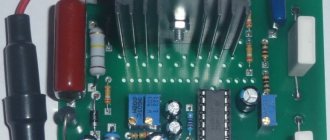
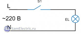
Scheme
A PWM regulator with a built-in switch MC34063 regulates the voltage on the motor.
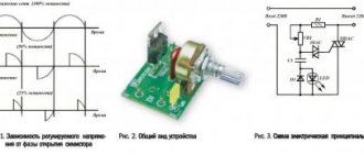
The voltage on the shunt R7, R9, R11 is amplified by the operational amplifier and, through a comparator, supplied to the feedback input of the PWM controller. If the current is less than a certain value, then a voltage is applied to the motor, depending on the resistance setting RV1. That is, at idle speed only part of the power will be supplied to the engine, and the trimming resistor RV1 will allow you to adjust the speed at the same time.
If the signal at the output of the op-amp exceeds the voltage on the comparator, then the full supply voltage will be supplied to the motor. That is, when drilling, the engine will turn on at maximum power. The switching threshold is set by resistor RV2. A linear stabilizer is used to power the op-amp.
All components of the circuit will dissipate very little heat and it can be assembled entirely using SMD components. It can operate over a wide range of supply voltages (depending on resistance R6), and does not require controllers or speed sensors.
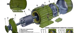
Do-it-yourself repair of a drill gearbox
If there is a need to disassemble a tool (breakage, simply replacing a part, or another reason), then it makes sense to pay attention to the gearbox and evaluate its technical condition. Perhaps some parts of the transmission mechanism have worn out
In most drills, the gearbox is designed quite simply - two flat gears, which are made of metal or hard plastic. For diagnostics, it is worth blocking the motor spindle and trying to turn the gears
In this case, it is important to evaluate the degree of backlash, and also check whether there is slippage at different transmission points
When it comes to a professional tool, the gearbox can be equipped with a gear selector or contain an adjustable safety clutch. Only these parts cannot be repaired. Therefore, we have to install new ones.
To replace the gear, you cannot do without the help of a circlip remover.
When removing a part, it is important not to lose the key, since it is very difficult to find a replacement. When carrying out DIY repairs on an impact drill, when the gearbox has already been disassembled, you should remove the armature completely, which will allow you to evaluate the smoothness of operation and check for play in the bearings
Armed with an awl, you can remove the protective covers of the separator to ensure its safety. For the mandrel, it is best to choose a copper tube or a wooden block with a longitudinal hole.
After performing manipulations with the gearbox, you need to remove any remaining grease and fill the chamber with new molybdenum paste (up to 2/3 of the volume). Before reassembling in reverse order, you should make sure that there are no foreign objects.
List of components
Here is a complete list of everything needed for assembly:
- Printed circuit board (link to manufacturing files at the end of the article)
- U1 - MC34063AD, switching regulator, SOIC-8
- U2 - LM358, operational amplifier, SOIC-8
- U3 - L78L09, stabilizer, SOT-89
- D1,D3 - SS14, Schottky diode, SMA - 2 pcs
- D2 - LL4148, rectifier diode, MiniMELF
- C1 - capacitor, 10uF, 50V, 1210
- C2 - capacitor, 3.3nF, 1206
- C3, C4 - capacitor, 4.7 µF, 1206 - 2 pcs
- C5 - capacitor, 22uF, 1206
- R1-R3,R7,R9,R11 - 1 Ohm resistor, 1206 - 6 pcs.
- R4, R10 - resistor 22 kOhm, 1206 - 2 pcs.
- R5 - 1kOhm resistor, 1206
- R6 - resistor 10-27 kOhm, 1206. The resistance depends on the rated voltage of the motor used. 12V - 10kOhm, 24V - 18kOhm, 27V - 22kOhm, 36V - 27kOhm
- R8 - resistor 390 Ohm, 1206
- RV1, RV2 - subscript resistor, 15 kOhm, type 3224W-1-153 - 2 pcs.
- XS1 - terminal, 2 pins, pitch 3.81mm
We also made a limiter ring on a 3D printer for easy installation on the engine. The download link for the STL file is at the end of the article.
Replacing a button
As for the starting mechanisms, which do not have a speed controller and the direction of rotation of the engine, not everything is so simple here. Although their design is somewhat lightweight, it is still quite complex. However, there is often no point in repairing the drill button yourself, since it is much more practical to install a new one.
To do this, you should visit the nearest store that sells spare parts for electric tools.
Here you need to take into account an important nuance. There is a great variety of drill models, so not all buttons are absolutely identical. When going shopping, you need to copy the data of the old part onto a sheet of paper. But even with such actions, misunderstandings may arise, since there is a possibility that the purchased button with the same parameters will not be installed in the body of the power tool, since there are differences in the design of this mechanism, which makes it impossible to secure it.
For this reason, the best option is to take the old button with you and use it to select a new part with exactly the same parameters, including dimensions.
Tags: machine, beat, sconce, view, engine, house, , clamp, replacement, sign, insulation, cable, like, capacitor, design, , magnet, installation, multimeter, voltage, nominal, rule, principle, wire, start , , work, size, regulator, resistor, relay, repair, rheostat, row, connection, resistance, means, term, circuit, type, current, , photo, shield, power tool, anchor
Assembly and configuration
Everything is assembled quite simply.
The contact pads are designed for hand soldering. It is worth starting assembling the board itself by installing all the components on the side of the board without trimmers, and then on the reverse side. It is easier to install the terminal last. The R6 rating is selected according to the rated voltage of your motor. In this device, it is important to control the position of the key on the microcircuits and the polarity of the diodes. All other components are non-polar. Place a spacer between the board and the motor above so that the board does not touch the motor. The board itself is placed directly on the engine lamellas. Check the polarity of the motor connection several times so that it turns to the right, and then solder the contacts.
Contacts for supplying voltage, the board input is labeled “GND” and “+36V”. The negative of the input voltage source is connected to the “GND” contact, and the positive to “+36V”. The power supply voltage must match the rated voltage of the motor.
Setting up the controller is very simple:
- Set the regulator response threshold to the maximum using resistor RV2
- Set resistor RV1 to the optimal engine speed in idle mode
- Set the response threshold with resistor RV2 so that when the slightest load appears, the voltage on the motor increases
Mechanical damage
Why does the device still not function if you have checked everything and ruled out breakdowns in the electrical circuit of the drill? There can be only one answer - the non-working condition of the product arose due to the presence of mechanical faults.
- Bearings don't work. Dust gets into the lubricant due to a breakthrough in the oil seal, so they wear out quickly and may at some point jam. It’s easy to fix: wash the bearing in kerosene, change the seals, fill it with new grease, preferably a special composition for products with high rotation speeds.
- A broken gearbox is a very serious failure; you need spare gears, or you will have to replace the entire module. You only need to install the same model. If the drill is a common modification, then buying spare parts for it in stores is not a problem.
- Experts consider the breakdown of cartridge parts to be another of the most difficult malfunctions.
We tried to talk about all the failures that occur during the operation of electric drills. Remember that DIY repairs are always much cheaper than buying a new product.
Sometimes a construction tool becomes a victim of malfunctions at the most inopportune moment. To correctly repair an electric drill, you need to understand how the tool works. Below we describe the features of an electric drill and give recommendations on what to do in case of the most common problems.
Disassembled drill
Symptoms of electric drill problems
Every electric drill system can fail. You can determine the causes of a malfunction by knowing their main symptoms.
Mechanical defects
The following signs indicate that the problem lies in one of the mechanical devices:
- jamming of the cartridge, inability to turn it by hand;
- metallic knocking and grinding noises during operation;
- crunch of plastic inside the case;
- hum of worn-out bearings, increased vibration;
- the impact mechanism does not turn on;
- the cartridge flies off the working shaft.
Mechanical failure can lead to malfunctions that occur periodically. Don't expect it to correct itself. As soon as the first signs of a problem are detected, it is necessary to stop work and eliminate the defect. Otherwise, the cost of repairs will increase significantly.
Signs of electrical failure
The electrical part also has its own characteristic signs of malfunction:
- the drill does not start, the motor does not rotate;
- the motor hums, but does not work;
- brushes spark strongly;
- The speed controller does not work, the speed does not change;
- The reverse does not work, the cartridge rotates only in one direction;
- the engine runs unstably, sometimes breaking at high speeds;
- there is a characteristic smell of smoldering wiring;
- The drill body gets hot.
How to repair an anchor at home
A third of screwdriver failures occur due to the anchor. With everyday intensive operation, malfunctions can occur within the first six months, for example, if the brushes are not replaced in a timely manner. With gentle use, the screwdriver will last a year or more.
The anchor can be saved if the balance is not disturbed. If during operation of the device you hear an intermittent hum and there is strong vibration, then this is an imbalance. This anchor must be replaced. And the winding and commutator can be repaired. Small short circuits are eliminated. If a significant part of the winding is damaged, it can be rewound. Worn and badly damaged lamellas should be sharpened, extended or soldered. In addition, you should not undertake anchor repairs if you are unsure of your capabilities. It is better to replace it or take it to a workshop.
Collector groove
Over time, wear from the brushes forms on the commutator. To get rid of it, you need to:
- Grind the commutator using cutters for longitudinal grinding, that is, through cutters.
- We also need a reverse cone for centering on the bearing. Make a hole in it up to 8 mm.
- Since copper is malleable, adjust the machine to a speed of 600 to 1500 rpm.
- Primary feed in half divisions. When the cutter lightly touches the product, make a longitudinal groove of the entire collector. Based on the resulting shiny pattern, you will see the condition of the lamellas and all surface irregularities.
- If the collector is level, then the groove will be uniform.
- If there are holes, continue grooving until the surface is level.
- For the last pass, you need to move the cutter one-fourth from the division.
- To polish, take thousand-grit sandpaper and turn on the machine so that the armature rotates in the direction in which it rotates during operation.
Don't forget to clear the rotor of chips to prevent a short circuit.
Video on the topic
How to rewind an anchor
Before disassembling the armature, write down or sketch the direction of the winding. It can be left or right. To determine it correctly, look at the end of the armature from the commutator side. Wear gloves and take sharp wire cutters or a hacksaw. Remove the winding end parts. The collector needs to be cleaned, but it is not necessary to remove it. Carefully, without damaging the slot insulators, knock out the rods of the remaining parts of the winding using a hammer and metal chisel.
Video: Removing the winding
Using a needle file, without damaging the insulator film, remove the remaining impregnation. Count the conductors in the slot. Calculate the number of turns in the section and measure the diameter of the wire. Draw a diagram. Cut cardboard sleeves for insulation and insert them into the grooves.
Video: Winding left and right
After winding, weld the section leads to the collector cocks. Now check the winding with a short circuit tester and indicator. Proceed with impregnation.
Instructions for impregnation (taking into account the speed controller)
- After making sure that there are no problems, send the armature to the electric oven to warm up for better flow of the epoxy resin.
- After warming up, place the anchor on the table at an angle for better spreading over the wires. Apply resin to the frontal area and slowly rotate the anchor. Drip until glue appears on the opposite frontal part.
- Place the anchor horizontally and drip onto both frontal parts. Twist the anchor until it loses fluidity.
- Leave in a vertical position until complete polymerization.
At the end of the process, lightly grind the commutator. Balance the anchor using a dynamic balancer and an angle grinder. Now make the final grind on the bearing. It is necessary to clean the grooves between the lamellas and polish the collector. Make a final check for opens and shorts.
The peculiarity of the winding for angle grinders with adjustable speed is that the rotor is wound with a power reserve. Current density affects the number of revolutions. The wire cross-section is too high and the number of turns is too low.