Physics with formulas ›
In this chapter...
- We generate electric current by moving the conductor
- Catching the magnetic flux
- We determine the direction of magnetic induction using Lenz's rule
- We take into account inductance and capacitance with alternating current
- Calculate the resistance of the oscillatory circuit
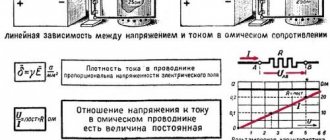
In this chapter, we begin to study alternating current, i.e. electric current with variable voltage and current. This current has an unusual resistance that varies with frequency, called electrical impedance. But impedance is just one of the many “delicacies” of this chapter. It also talks about the inductive and capacitive reactance created by capacitors and inductors, as well as other properties of alternating current electrical circuits.
Inducing electromotive force
If you try to change the magnetic flux (see Chapter 18) through a surface bounded by a conducting circuit, then an electromotive force (emf) will arise in it, which is proportional to the rate of change of the magnetic flux. The electric current caused by this EMF is called induced current, and the phenomenon itself is called electromagnetic induction.
Magnetic flux can be represented as a certain number of magnetic field lines running perpendicular to the surface.
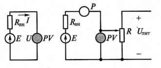
Let's try to find the emf. electromagnetic induction of a conducting circuit with a rod moving in a magnetic field (Fig. 19.1). Voltage (electromagnetic induction emf) is induced in the rod precisely due to the movement of the rod in the magnetic field. As a result, an electric current will arise in a closed conductive circuit. Let a metal rod be 1 m long and move at a speed of 100 km/h (about 28 m/s) in a magnetic field of 1 T. What voltage will be at the edges of the rod if it moves at right angles to the magnetic field? You just need to substitute the values into the following formula:
At right angles at the edges of the rod there will be a voltage of about 28 V. How is this formula obtained?
We create voltage by moving a conductor in a magnetic field
In Fig. 19.1, a metal conductor rod moves with speed v to the right along metal guides and is in a magnetic field directed from the reader perpendicular to the plane of the page. What is happening from a physics point of view?
An electric charge \( q \) inside a metal rod moves in a magnetic field with a speed \( v \), so a force acts on it:
where \( q \) is the electric charge and \( B \) is the magnetic induction.
It is this force that induces an electric current. It corresponds to the electric field strength \( E \), which is calculated using the following formula:
The work \( A \) to move a charge \( q \) to a distance \( L \) in such an electric field is determined by the formula:
Where do we get the formula for voltage (see the definition of voltage in Chapter 16):
We express the voltage through the change in the contour area
Let's see how the contour area changes in the example in Fig. 19.1. Let a metal rod pass a distance \(\Delta x \) during the time \( \Delta t \) through the magnetic field. We can say that \( v= \Delta x/\Delta t \), resulting in:
Now let's see what the product \( \Delta xL \) is. This is the distance that a rod travels in some time multiplied by the length of that rod. Looking at Fig. 19.2, you will see that \(\Delta xL\) is equal to the area \(\Delta S\) covered by the rod during its movement (this area is shaded).
So, if the rod travels a distance \( \Delta x \) in time \( \Delta t \), then the change in the area of the closed region is equal to \( \Delta S=\Delta xL/\Delta t \). Then the emf formula electromagnetic induction can be written as follows:
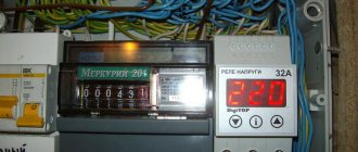
Phase (Phase Voltage) Misalignment in a Three-Phase Electrical Network
• Essence of the phenomenon • Causes of occurrence • Consequences • Methods for eliminating phase imbalance • Alternative technology. • Range of changes in phase voltages.
• Practical use.
The essence of the phenomenon
Phase imbalance manifests itself in three-phase four- (five-) wire networks with a solidly grounded neutral with voltages up to 1000 V.
As a rule, a low-voltage three-phase electrical network with a voltage of 400 V (0.4 kV) contains sources of electricity, the windings of which are connected in a “star” with a zero output.
If a three-phase network is four-wire, then the neutral conductor performs two functions. First function: the neutral working conductor is used to connect single-phase electrical receivers. Second function: the neutral working conductor is used to operate the protection. In a five-wire network, each of the two listed functions has its own wire.
In low-voltage networks, primary and secondary sources of electricity (power supplies) are distinguished, regardless of the method of obtaining electrical energy.
Primary sources include those that directly generate electricity, for example, electric generators (hydraulic units, steam turbines, diesel engines, and gas engines can be used as drives).
Secondary sources include those that convert electrical energy from primary sources, as a rule, these are transformers installed in transformer substations (TS).
An ideal model that displays the relationship and relative position of phase and line voltages can be depicted in the form of an equilateral triangle with vertices “A”, “B”, “C” and .Vectors AB, BC and CA (lying on the sides of the triangle) are line voltages (380V ).The vectors drawn from the center of the triangle to its vertices - 0A, 0B and 0C - are phase voltages. Ideally, they are equal to each other 0A=0B=0C and shifted relative to each other by an angle of 120°, that is└A0B=└B0C =└C0A=120°.
This model is ideal and there is no phase voltage imbalance.
Since many consumers, including single-phase ones, are connected to TP transformers, at every random moment in time one can expect that the loads in different phases will be different. Moreover, even if single-phase loads are the same in size, then their switching on or off under load cannot occur synchronously. The situation arises RA > RB > RC ≠ 0, where “R” is the load resistance, and, accordingly, “RA” is the load resistance on phase A, “RB” is the load resistance on phase B, “RC” is load resistance on phase C.
The difference in phase loads in magnitude and nature creates conditions for the occurrence of phase voltage imbalance.
If we look at the equilateral triangle described above, then graphically it will look like this: point 0 in the center of the triangle, from which the vectors of ideal phase voltages of 220V 0A, 0B and 0C emanate, is shifted relative to the center of the triangle. Let's call it 0′.
The phase voltage vectors themselves are shifted at an arbitrary angle relative to each other. The displaced phase voltage vectors 0'A, 0'B and 0'C are not equal to each other, 0'A ≠ 0'B ≠ 0'C.
The voltage on each phase changes from a value of 220 V, for example, to 190 V, 240 V and 230 V, respectively.
This situation is called phase voltage imbalance.
If the load resistances were equal, then the currents flowing through them would also be equal to each other. Considering that the shift angle between them is 120°, their geometric sum would be equal to zero.
However, if they are unequal, as a result of summation, a current I00′ arises, which is called equalizing. And, therefore, the voltage U00′, which is called the bias voltage.
Phase imbalance (phase voltages), as a rule, is characterized by the invariance or sameness of the line voltages of the source and a significant difference in the magnitude of the phase voltages.
That is, the equilateral triangle formed by the vectors of linear voltages remains an equilateral triangle, this means that the value of the three linear voltages corresponds to 380V, minor deviations of the values are possible, which are called acceptable.
The phase voltage vectors inside the triangle, which connect the point inside the triangle with its vertices, shift significantly, the magnitude of the phase voltages and the shift angle between them change.
Causes of phase imbalance
Conventionally, the causes of phase imbalance can be divided into external and internal.
Internal reasons are associated with electricity consumers who unevenly load the network phases without taking into account the power of single-phase electrical receivers, the simultaneity factor of their inclusion,
connect powerful two-phase electrical receivers to household sockets.
In real life, the cause of phase imbalance is uneven loading not only in size, but also in the nature of the load. The load can be active (resistive) - (R) or reactive: inductive (L) or capacitive (C).
External causes of phase imbalance may be associated with faults in the distribution network (for example, in high-voltage power lines (PTL)
at high humidity and defects in strings of insulators or arresters of individual phases) or the presence of powerful consumers connected to two phases, i.e. to line voltage (for example, consumers of traction networks or electric motors of electric trains).
Also, the reasons can be combined (external and internal).
Consequences of phase imbalance
The consequences of phase imbalance are manifested in an increase in power consumption from the network; in the incorrect operation of electrical receivers, their malfunctions, failures, shutdowns, blown fuses, and wear of insulation.
Conventionally, the negative consequences of phase imbalance can be divided into three groups:
1. Consequences for electrical receivers (devices, equipment) associated with their damage, failures, increased wear, and reduced service life.
a) consequences for single-phase electrical consumers Low voltage causes incorrect operation of single-phase consumers: dim light of lighting devices, prolonged heating of heating devices, prolonged start-up of motor devices, computer malfunctions, etc. High voltage causes failures of electrical receivers due to wear of the insulation, switching them off by protective devices, and blown fuses.
b) the consequences of phase imbalance for three-phase power consumers. The main part of three-phase consumers (consumers powered by line voltage) are electric motors that drive submersible and sewage pumps, automatic gate drives, machine tools, etc. The control and monitoring system for the launch of such three-phase consumers, as a rule, is connected to phase voltage.
We calculate electromagnetic induction using Faraday's law
In the previous formula for calculating the emf. electromagnetic induction:
the quantity \( B\Delta S \) is called magnetic flux. Magnetic flux is a measure of how much flux of the magnetic induction vector passes through some surface. For example, when the magnetic induction doubles, its flux will also double. The unit of measurement of magnetic flux in the SI system is weber (Wb), 1 Wb = T m2, and magnetic flux is denoted by the Greek letter \( \mathbf{Ф} \). (In the CGS system, the unit of magnetic flux is the maxwell (Mks); 1 Wb = 108 Mks.)
Thus, the formula for e.m.f. induction:
converted to:
where is the change in magnetic flux \( \Delta \mathbf{Ф}=\Delta S/\Delta t \).
From the last formula it follows that the created emf. electromagnetic induction is the rate of change of magnetic flux. However, this is not the final formula yet. It is usually written with a minus sign (this sign, which appears thanks to Lenz’s rule, is discussed in more detail in the next section):
The minus sign means that the emf created. Electromagnetic induction in turn creates a current that will resist changes in magnetic flux. This formula is called Faraday's law. Typically, the formulation of this law uses a magnetic flux passing through a coil with \( N \) turns.
If there is a coil with \( N \) turns and the magnetic flux passing through it changes, then, according to Faraday’s law, the emf created in this coil. electromagnetic induction is calculated by the formula:
How does the magnetic flux change in a coil if its dimensions do not change? This occurs due to a change in either the magnitude of the magnetic field or the surface area that the magnetic field penetrates. In Fig. Figure 19.4 shows a top view of the coils located at an angle to the magnetic induction vector. Thus, when the angle \( \theta \) changes, the flux passing through the coil also changes
As you can see, the e.m.f. electromagnetic induction can be created in a coil in two ways: when the magnitude of the magnetic field changes or when the angle between the coil and the lines of magnetic induction changes, i.e. the area of the circuit, and therefore the magnetic flux that penetrates the circuit.
Determining the sign using Lenz's rules
When a magnetic field penetrates a circuit, an emf is generated in it. electromagnetic induction, i.e. a certain energy is spent to create an electric field. And after its creation, this entire system resists any changes.
If you create a huge magnetic field penetrating a wire loop, and then suddenly turn off the source of the magnetic field, you will notice that the magnetic field passing through the loop does not disappear immediately, but gradually. Why is this happening? The fact is that the emerging emf. electromagnetic induction causes current to flow in such a way that it maintains the achieved stable state, i.e. kept the magnetic field unchanged.
This is the essence of Lenz's rule: emf. electromagnetic induction will act so that the resulting current creates an induced magnetic field that opposes the change in flux.
Let the magnetic field penetrating the circuit change over time, as shown in Fig. 19.5. Then the e.m.f. electromagnetic induction will act in such a way as to maintain the existing position, i.e. will create an induced magnetic field, which, as shown in Fig. 19.5, counteracts the increase in the already existing magnetic field.
Pay attention to the direction of the induced current in the circuit. If you point the fingers of your right hand (except the thumb, which is set to the side) along the turns of the coil in the direction of current flow, then the thumb of this hand will point in the direction of the induced magnetic field (you can learn more about the rule of the right and left hands in Chapter 18). It is this field that will counteract the increase in the magnetic field already applied to the coil.
Knowing Lenz's rule, you can always determine the direction of the induction current - it is directed so as to maintain the existing position. If the magnetic flux increases, then the induced current creates an induced magnetic field, which tries to prevent the flux from increasing. And if the magnetic flux decreases, then the induction current is directed so as, on the contrary, to increase the flux.
Try to check the knowledge you just gained using Fig. 19.5. Where is the current directed if the external magnetic flux passing through the circuit increases over time?
Calculating inductance
How strongly can a circuit resist a change in the magnetic flux passing through it? This ability to counteract is determined by its inductance. What it is?
If a current of force \( I \) flows in a conducting circuit, creating a magnetic field, then the magnitude of the magnetic flux \( Ф \) passing through the circuit is related to the magnitude of the current as follows:
The proportionality coefficient \( L \) is called inductance (or, strictly speaking, the self-inductance coefficient of the circuit. - Ed. note). Inductance depends on the size and shape of the circuit, as well as on the magnetic permeability of the environment.
The well-known Faraday law (see above), according to which the emf. electromagnetic induction is proportional to the change in flux through a coil with \( N \) loops-turns
Let's rewrite it in a slightly different form. Let's change this formula by introducing inductance into it:
where \( L_{cat} \) is the inductance of the entire coil with \( N \) circuits and turns.
Here, all \( N \) turns of the coil are penetrated by the total magnetic flux \( NF \), which is proportional to the strength of the current \( I \) passing through the coil, with a proportionality coefficient \( L_{cat} \) , i.e. \(NF=L_{cat}I \).
In the SI system, inductance is measured in henry (H), 1 H = 1 Wb/1 A.
The quantity \( L \) is not just a proportionality coefficient, but a coefficient of self-inductance of the circuit. It shows how strongly the circuit can respond to changes in flow. When the strength of the current passing through it changes, we get a change in the magnetic flux, and the larger \(L\), the better the circuit counteracts the change in current, creating its own current. This means that the circuit can resist sudden changes in the current flowing through it, since its inductance tries to counteract any change in flow. For this reason, the coils used in electrical circuits are called inductors.
Chapter 16 describes some circuit elements that deal with electric fields, namely resistors and capacitors. Now another type of circuit element has been added to them, namely inductors, which have a very useful quality for their use in electrical circuits. In a capacitor, the charge does not change instantly, but gradually, which allows you to smoothly change the voltage in electrical circuits. Likewise, the strength of the current flowing through the inductor also does not change instantly, but gradually, which allows it to change smoothly in electrical circuits.
We study AC and voltage circuits
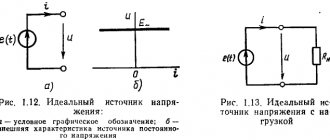
The unique behavior of capacitors and resistors in electrical circuits becomes truly useful when current and voltage change over time—in other words, when dealing with alternating currents and alternating voltages. For example, electrical power from a household outlet is characterized by variability in current and voltage. In alternating current, the direction of the current and the sign of the voltage periodically change to the opposite. In Fig. Figure 19.6 shows an example of an AC electrical circuit (bottom) and a graph of voltage versus time (top).
At the bottom, the circle with a winding line indicates an alternating current source; the voltage it creates is shown in the upper part of Fig. 19.6.
We estimate the average value of alternating voltage
What does AC voltage feel like? There are many ways to change voltage using electrical circuits, but the most common method generates a sinusoidal wave, shown in Fig. 19.6, as alternating voltage fluctuations from a household outlet.
Borrowing some concepts from rotational motion (see Chapter 7), stress can be expressed mathematically:
where \( U_0 \) is the maximum voltage, \( f \) is the frequency of voltage fluctuations (for example, 50 Hz for current from a home outlet in the CIS countries), and \( t \) is time. What is the current produced by this voltage when the switch is closed? In the circuit shown in Fig. 19.6, the only element (other than the switch, which can be considered a simple conductor) is a resistor (see Chapter 17). A resistor does not respond to changes in voltage and current the way capacitors and inductors do. For a resistor, it doesn't matter how the voltage changes. Its resistance \( R \) remains constant and does not depend on the rate of change of voltage and current. The voltage \( U \) and the current \( I \) on it are always related by the well-known law:
Therefore, the current strength is expressed by the following formula:
What about the power dissipated in the circuit, i.e. power that the resistor dissipates as heat? From Chapter 17 we know that power \( P = IU \), but since voltage and current change over time, it cannot be said that \( P = I_0U_0 \). In fact, the instantaneous AC power \( P_{mg} \) is determined by the formula:
Since, when averaging over a period, the last term becomes equal to zero, the average alternating current power \( P_{average} \) is equal to:
Often this formula is written as follows:
The quantities \( I_{eff} \) and \( U_{eff} \) are called the effective (or effective) current value and the effective (or effective) voltage value.
Finding the effective values of current and voltage
Using the RMS values of current and voltage, you can obtain the power dissipated in a resistor from an electrical circuit using one of the following expressions (in which the power dissipation is calculated in the same way as for constant currents and voltages):
The resistor deals with alternating current, for which the formula \( U=IR \) is always true, unless \( U \) is the voltage at the ends of the resistor, and \( I \) is the current strength, going through it. Therefore, if the formula for the voltage at the ends of the resistor is:
then the current flowing through the resistor is calculated by the formula:
Thus, if at the top of Fig. Figure 19.7 shows the voltage at the ends of the resistor, then the lower part of this figure shows the current flowing through the resistor.
This is simple enough, but how does changing voltage and current affect inductors and capacitors?
Anticipating voltage using capacitors
In Fig. Figure 19.8 shows a circuit with a capacitor in an alternating current circuit. From the previous sections it is known that for resistors in an alternating current circuit \( U_{eff}=I_{eff}R \). How to connect the voltage at the ends of the capacitor with the current flowing through it?
Using the following formula:
It is similar to the previous formula \( U_{eff}=I_{eff}R \), but what else is this parameter \( R_c \)? This is the capacitance of the capacitor, which allows you to estimate how much the capacitor can act like a resistor when the frequency changes. Capacitance is measured in ohms, just like the resistance of a resistor, and based on measurements taken during experiments, it became known that:
where \( f \) and \( C \) are the frequency and capacitance, respectively.
We measure the current flowing through the capacitor
Knowing the voltage applied to the capacitor, you can calculate the current flowing through it. Let the capacitance of the capacitor in Fig. 19.8 is 1 µF (1 microfarad, 1 µF = 10-6 F; see Chapter 16 for more information on capacitance and its units), and the effective value of the applied voltage is 12 V. What will be the current at a frequency of 10 Hz and 104 Hz? Based on the above formulas:
we get for 10 Hz:
and for 104 Hz:
The difference is considerable, and all thanks to the change in frequency. As you can see, when working with capacitors (as opposed to resistors), you need to seriously consider frequency.
Looking at instantaneous values
Using averaged (effective) values, you can effectively work with parameters whose instantaneous values change over time. The capacitor is alternately charged and discharged without wasting energy on heat, i.e. in an AC circuit, a capacitor does not end up wasting energy (unlike a resistor). Since current and voltage change over time, a good indicator of what is happening is the RMS value (which is the average value over the period of oscillation). It is the actual voltage value of 220 V that is indicated on a regular household outlet.
Let us now consider what is not effective, i.e. value averaged over some time, and real instantaneous, i.e. time-dependent value. In Fig. Figure 19.9 shows a graph of the voltage from the source in Fig. 19.8. What then will be the current graph?
As you can see in the figure, the current graph has the same shape as the voltage graph, but is slightly shifted to the left. Since the horizontal coordinate axis denotes time, it is clear that the current reaches its peak before the voltage, or, as physicists say, ahead of the voltage. In reality, the peak current values are a quarter of a period ahead of the voltage, therefore the current reaches a certain “height”, i.e. peak value before the voltage does so. So if:
(note that instead of \( 2\pi\!f \) there is \( \omega \), as in Chapter 7, when we were talking about angular motion), then:
Here's how to comment on these expressions. Let the current reach its peak and begin to decline. However, having passed its peak and decreasing in value, it still remains positive, i.e. continues to accumulate charge on the capacitor. And since the capacitor voltage is \( U = Q/C \), where \( Q \) and \( C \) are the charge and capacitance, respectively, the voltage continues to rise as long as the current is positive. Only when the current becomes negative (after crossing the horizontal axis) does the charge begin to leave the capacitor, and then the voltage begins to decrease.
The fact that the current strength is ahead of the voltage sounds like this in the language of physics: the current strength and voltage are shifted in phase. In a resistor, where \( U=IR \) and there is no dependence on time, the voltage and current always have the same phase. And in a capacitor, where the current leads the voltage by a quarter of a period, which is \(\pi/2\), the current and voltage are out of phase by \(\pi/2\). This phenomenon observed in a capacitor can be described differently: the current leads the voltage by \(\pi/2\), or the voltage \(\pi/2\) lags behind the current.
The voltage and current amplitudes in the capacitor can take different values. In Fig. In Figure 19.8, these quantities are shown with the same amplitude so that the phase difference can be clearly seen.
Now let's move on to mathematics. If the voltage applied to the capacitor is expressed by the formula:
as is known:
In trigonometry \( \sin(\omega t+\pi/2)=\cos(\omega t) \), therefore:
This equality makes the phase difference in the capacitor between voltage and current very clear: these quantities change like the sine and cosine of the angle \( \omega t \), respectively, and the sine and cosine are shifted in phase by 90°, i.e. by \( \pi/2 \).
This equality can be rewritten using \( U_0 \), for example, like this: \( I=(U_0/R_C)\!\cos(\omega t) \).
We lag behind the voltage using inductors
In Fig. Figure 19.10 shows a wavy thing that looks like a spring. This is how electrical circuits indicate an inductor, which, like capacitors, reacts to alternating voltage.
How does an inductor react to alternating voltage? Same as a capacitor:
but the formula relating the effective values of voltage and current for an inductor is as follows:
What is \( R_L \)? This is the inductive reactance of the coil, which indicates (much like the resistance of a resistor) how strongly the coil will resist a change in voltage. It is measured in ohms and, as is known, is equal to:
where \( L \) is the inductance of the coil, measured in henry (H). Inductive reactance is directly proportional to inductance, and capacitive reactance is inversely proportional to capacitance:
Like a capacitor, an inductor alternately stores and releases electrical charge without dissipating any energy in an AC circuit to heat. If the voltage supplied from the source depends on time according to the formula:
then how does the current passing through the inductor behave? The answer can be seen in Fig. 11.19. This time, the current lags behind the voltage, and the voltage, on the contrary, leads the current, i.e. we have a situation exactly opposite to that observed with a capacitor.
Why are the current and voltage shifted in phase, and in the direction opposite to the phase shift of capacitors? Look at the graph shown in Fig. 11.19.
When the current reaches its maximum and minimum values, its change at these points is zero. Consequently, the electromagnetic induction voltage, which takes into account all changes in the magnetic flux in the coil, is also zero at these points. Therefore, current and voltage are out of phase. If the voltage applied to the coil is calculated by the formula:
then, due to the current lagging behind the voltage, its formula will be as follows:
In an inductor, the current lags behind the voltage by a quarter of a period, which means that the current reaches a certain height, for example, its peak value, after the voltage does.
The last formula can also be written this way:
This equality makes the phase difference in the inductor between current and voltage very clear: these quantities change like the cosine with a minus sign and the sine of the angle \( \omega t \), and the cosine with a minus sign and sine out of phase by 90°, i.e. \( \pi /2 \).
This equality can be rewritten using \( U_0 \), for example, like this: \( I=-(U_0/X_1)\!\cos(\omega t) \).
AC current and voltage phase shift
DC power, as we already know, is equal to the product of voltage and current. But with constant current, the directions of current and voltage always coincide. With alternating current, the coincidence of the directions of current and voltage occurs only in the absence of capacitors and inductors in the current circuit.
For this case, the power formula
remains fair.
Figure 1 shows the curve of changes in instantaneous power values for this case (the direction of the current and voltage are the same). Let us pay attention to the fact that the directions of the voltage and current vectors in this case coincide, that is, the phases of the current and voltage are always the same .
Figure 1. Phase shift of current and voltage. There is no phase shift, the power is always positive.
If there is a capacitor or inductor in the AC circuit, the phases of the current and voltage will not coincide.
Read about the reasons for this discrepancy in my textbooks for a capacitive circuit and for an inductive circuit, but now let’s establish how it will affect the amount of alternating current power.
Let's imagine that at the beginning of rotation, the radius vectors of current and voltage have different directions. Since both vectors rotate at the same speed, the angle between them will remain constant throughout their rotation. Figure 2 shows the case when the current vector Im behind the voltage vector Um by an angle of 45°.
Figure 2. Phase shift of current and voltage. The phases of current and voltage are shifted by 45, the power becomes negative at some periods of time.
Let's consider how the current and voltage will change. From the constructed sinusoids of current and voltage, it can be seen that when the voltage passes through zero, the current has a negative value.
Then the voltage reaches its maximum value and begins to decrease, and the current, although it becomes positive, has not yet reached its maximum value and continues to increase. The voltage has changed its direction, but the current still flows in the same direction, etc. The current phase always lags behind the voltage phase. shift between the voltage and current phases , called phase shift.
Indeed, if we look at Figure 2, we will notice that the current sinusoid is shifted to the right relative to the voltage sinusoid. Since we plot the degrees of rotation along the horizontal axis, the phase shift can also be measured in degrees. It is easy to see that the phase shift is exactly equal to the angle between the radius vectors of current and voltage.
Due to the current phase lagging behind the voltage phase, its direction at some moments will not coincide with the direction of the voltage. At these moments, the current power will be negative, since the product of a positive value and a negative value will always be negative. This means that the external electrical circuit at these moments becomes not a consumer of electrical energy, but a source of it. Some of the energy supplied to the circuit during the portion of the period when the power was positive is returned to the energy source during the portion of the period when the power is negative.
The greater the phase shift, the longer the parts of the period during which the power becomes negative become, and, consequently, the less will be the average current power.
With a phase shift of 90°, the power will be positive for one quarter of the period and negative for the other quarter of the period. Consequently, the average power of the current will be zero , and the current will not produce any work (Figure 3).
Figure 3. Phase shift of current and voltage. The phases of current and voltage are shifted by 90, the power is positive during one quarter of the period, and negative during the other. On average, the power is zero.
It is now clear that the alternating current power in the presence of a phase shift will be less than the product of the effective values of current and voltage, i.e. the formula
in this case will be incorrect
DID YOU LIKE THE ARTICLE? SHARE WITH YOUR FRIENDS ON SOCIAL NETWORKS!
Related materials:
- The concept of alternating current
- Receiving alternating current
- Period, frequency, amplitude and phase of alternating current
- RMS value of current and voltage
- AC power
Comments
#14 rrr 03.12.2018 14:20 Please tell me how to draw microprocessor circuits in this application. There are no necessary circuits in this library, and drawing with rectangles is very time consuming and not practical
Quote
#13 Almira 06/10/2018 06:52 Question: does the phase shift depend on the value of active resistance? If no/yes, why?
Quote
#12 Alexander 40 07/11/2017 19:15 why does a 220 volt transformer connected in series with the primary winding get very hot? Probably 220 is added to a charged capacitor of 1 microforad due to the phase shift and it turns out about 440 volts on the primary winding.
Quote
#11 Vitaly 12/15/2016 21:03 I quote the Master:
I quote Stas: What nonsense. When the phases are shifted by 90*, the current does not do any work. We take an electric hotplate, connect a capacitor in series and plug it into the socket, everything works, the hotplate heats up, the current does work.
Nobody said that it wouldn't warm up!
Read carefully! Tile - This is active power Even with a network shift of 90 degrees, the tile will not affect the angle and vice versa) if I’m wrong, correct me, just guesses) Quote #10 Rostik 06/07/2016 02:28 But the question is, is it possible to do this by taking one phase from the 220 network and throw one phase wire straight to the stove and the second wire from the same phase through the condenser and then to the electric stove, that is, make a phase circuit; will the stove work more powerfully or nothing will happen?
Quote
Sed 01/20/2016 17:57 topic not solved
Quote
Vladimir 24 12/03/2015 08:50 Thank you. The ongoing processes are described very intelligibly, clearly, and clearly. Nice article and useful.
Quote
zed 05/26/2015 08:25 Stas, if you connect a capacitor to a tile with active resistance, then there will be a phase shift, but not 90. Therefore, the tile will heat, but not as efficiently as without a capacitor... This is mathematics...
Quote
Andrey 12/28/2014 00:44 More articles like this, you’re a great author, I tried to understand a three-phase circuit many times and all the formula triangles were useless and it all ended there. Until I figured out to replace each winding with just a battery with a different voltage and direction as per the sine wave graph, and lo and behold, I began to combine and everything worked. Then I finally understood what zero is. For more people like you, these academics and so on are of no use. so they will write that life is not enough to figure it out. It feels like they are purposefully confusing so that only the smartest of the people can guess.
Quote
Master 10.22.2014 18:33 I quote Stas:
What nonsense. When the phases are shifted by 90*, the current does not do any work. We take an electric hotplate, connect a capacitor in series and plug it into the socket, everything works, the hotplate heats up, the current does work.
Nobody said that it wouldn't warm up!
Read carefully! Quote everything is absolutely correct 12/13/2013 14:18
Quote
Administrator 12/12/2013 07:42 Do not substitute concepts! The tile is a resistive load, in this case the phase difference between current and voltage is zero. And on the capacitor that you connected to the circuit, the voltage lags behind the current by 90 degrees (do not forget that the current when connected in series is common through all elements). Therefore, the power on the capacitor will change during one quarter of the period will be positive, and during the other quarter of the period it will be negative. Total for the period P=0. Therefore, the work will be zero. But in tiles it’s different, there is no shift P=I*U. For clarification, look at the pictures:
That’s why capacitors are used as “watt-free resistors”
Quote
Stas 12/11/2013 10:59 What nonsense. When the phases are shifted by 90*, the current does not do any work. We take an electric hotplate, connect a capacitor in series and plug it into the socket, everything works, the hotplate heats up, the current does work.
Quote
tmp 22.11.2013 18:05 Simple and accessible
Quote
Update list of comments
Add a comment
Fighting triple resistance: oscillatory circuit
In Fig. Figure 19.12 shows a typical oscillating circuit circuit with a “triple threat” in one electrical circuit: a resistor, an inductor and a capacitor.
How to estimate the total resistance of such a circuit? Now it needs to take into account the resistance of the resistor (see Chapter 17), as well as capacitive and inductive reactance (see previous sections in this chapter). Is the formula correct in this case:
No, unfortunately, it is not true, since over time the voltage in the resistor, capacitor and inductor change differently and their individual voltages cannot be summed up. Instead, you will have to introduce a new quantity - impedance \( Z \) (it is often called the complex resistance of the circuit):
What is the impedance \(Z\)? It is calculated using the following formula:
Let \( R_L \) = 16 Ohms, \( R_C \) = 12 Ohms, \( R \) = 3 Ohms, and \( U_{eff} \) = 10 V. What is the effective value of the current? First we find the impedance \(Z\) using the formula:
Then, using the equality \( U_{act}=I_{act}Z \), we get:
The effective current value is 2 A.
In addition, the phase difference between current and voltage (i.e., whether the current lags behind the voltage or advances it) can be determined by the following formula for the tangent of the phase shift \( \delta \) between the current and voltage:
Chapter 20. A little light on mirrors and lenses →
← Chapter 18. Magnetizing: attracting and repelling
Chapter 19. Calming current and voltage fluctuations
2.8 (55%) 4 votes
Phase shift between voltage and current
In general, the initial phases of current and voltage on a two-terminal network do not coincide. According to formula (3.20), the initial voltage phase is equal to
.
| And 3.37 | The phase difference (phase shift) of voltage and current is equal to . (3.24) |
If the angle is positive, then the phase of the voltage is greater than the phase of the current; in this case, it is said that the voltage leads the current in phase. If the angle is negative (at negative), then the phase of the voltage is less than the phase of the current, in this case it is said that the voltage lags behind the current in phase. If there are coils and capacitors in the circuit, then the circuit is in resonant mode.
Triangle of resistances
The resistance triangle (Fig. 3.5) is used to remember formulas (3.23) and (3.24)
And .
| And 3.38 | Rice. 3.5. Triangle of resistances |
From this triangle, according to the rules of trigonometry, two more formulas are obtained:
, .
| And 3.39 | There is a one-to-one correspondence between two pairs of parameters and , on the one hand, and and , on the other hand. Any passive two-terminal network in an alternating sinusoidal current circuit is completely characterized by either active and reactance ( and ), or impedance and phase angle ( and ). |
Comment
. In principle, it is enough to know any two parameters to determine the other two.