In order to obtain high-quality and beautiful soldering, it is necessary to correctly select the power of the soldering iron and ensure a certain temperature of its tip, depending on the brand of solder used. I offer several circuits of homemade thyristor temperature controllers for soldering iron heating, which will successfully replace many industrial ones that are incomparable in price and complexity.
Attention, the following thyristor circuits of temperature controllers are not galvanically isolated from the electrical network and touching the current-carrying elements of the circuit can lead to electric shock!
To adjust the temperature of the soldering iron tip, soldering stations are used, in which the optimal temperature of the soldering iron tip is maintained in manual or automatic mode. The availability of a soldering station for a home craftsman is limited by its high price. For myself, I solved the issue of temperature regulation by developing and manufacturing a regulator with manual, stepless temperature control. The circuit can be modified to automatically maintain the temperature, but I don’t see the point in this, and practice has shown that manual adjustment is quite sufficient, since the voltage in the network is stable and the temperature in the room is also stable.
Classic thyristor regulator circuit
The classic thyristor circuit of the soldering iron power regulator did not meet one of my main requirements, the absence of radiating interference into the power supply network and the airwaves. But for a radio amateur, such interference makes it impossible to fully engage in what he loves. If the circuit is supplemented with a filter, the design will turn out to be bulky. But for many use cases, such a thyristor regulator circuit can be successfully used, for example, to adjust the brightness of incandescent lamps and heating devices with a power of 20-60 W. That's why I decided to present this diagram.
In order to understand how the circuit works, I will dwell in more detail on the principle of operation of the thyristor. A thyristor is a semiconductor device that is either open or closed. to open it, you need to apply a positive voltage of 2-5 V to the control electrode, depending on the type of thyristor, relative to the cathode (indicated by k in the diagram). After the thyristor has opened (the resistance between the anode and cathode becomes 0), it is not possible to close it through the control electrode. The thyristor will be open until the voltage between its anode and cathode (labeled a and k in the diagram) becomes close to zero. It's that simple.
The classical regulator circuit works as follows. AC mains voltage is supplied through the load (incandescent light bulb or soldering iron winding) to a rectifier bridge circuit made using diodes VD1-VD4. The diode bridge converts alternating voltage into direct voltage, varying according to a sinusoidal law (diagram 1). When the middle terminal of resistor R1 is in the extreme left position, its resistance is 0 and when the voltage in the network begins to increase, capacitor C1 begins to charge. When C1 is charged to a voltage of 2-5 V, current will flow through R2 to the control electrode VS1. The thyristor will open, short-circuit the diode bridge and the maximum current will flow through the load (top diagram).
When you turn the knob of the variable resistor R1, its resistance will increase, the charging current of capacitor C1 will decrease and it will take more time for the voltage on it to reach 2-5 V, so the thyristor will not open immediately, but after some time. The greater the value of R1, the longer the charging time of C1 will be, the thyristor will open later and the power received by the load will be proportionally less. Thus, by rotating the variable resistor knob, you control the heating temperature of the soldering iron or the brightness of the incandescent light bulb.
Above is a classic circuit of a thyristor regulator made on a KU202N thyristor. Since controlling this thyristor requires a larger current (according to the passport 100 mA, the real one is about 20 mA), the values of resistors R1 and R2 are reduced, R3 is eliminated, and the size of the electrolytic capacitor is increased. When repeating the circuit, it may be necessary to increase the value of capacitor C1 to 20 μF.
Simple power regulator circuit
You can adjust the power of the soldering iron using analog or digital soldering stations for this purpose. The latter are quite expensive, and it is not easy to assemble them without experience. While analog devices (which are essentially power regulators) are not difficult to make with your own hands.
Here is a simple diagram of a device using thyristors, thanks to which you can regulate the power of the soldering iron.
The simplest regulator
Radioelements indicated in the diagram:
- VD – KD209 (or similar in characteristics)
- VS-KU203V or its equivalent;
- R1 – resistance with a nominal value of 15 kOhm;
- R2 – variable resistor 30 kOhm;
- C – electrolytic type capacitance with a nominal value of 4.7 μF and a voltage of 50 V or more;
- Rn – load (in our case it is a soldering iron).
This device regulates only the positive half-cycle, so the minimum power of the soldering iron will be half the rated one. The thyristor is controlled through a circuit that includes two resistances and a capacitance. The charging time of the capacitor (it is regulated by resistance R2) affects the duration of the “opening” of the thyristor. Below is the operating schedule of the device.
The influence of resistance R2 on the operation of the regulator
Explanation of the picture:
- graph A – shows a sinusoid of alternating voltage supplied to the load Rn (soldering iron) with a resistance R2 close to 0 kOhm;
- graph B – displays the amplitude of the sinusoid of the voltage supplied to the soldering iron with a resistance R2 equal to 15 kOhm;
- graph C, as can be seen from it, at the maximum resistance R2 (30 kOhm), the operating time of the thyristor (t2) becomes minimal, that is, the soldering iron operates with approximately 50% of the nominal power.
The circuit diagram of the device is quite simple, so even those who are not very well versed in circuit design can assemble it themselves. It is necessary to warn that when this device operates, a voltage dangerous to human life is present in its circuit, therefore all its elements must be reliably insulated.
As already described above, devices operating on the principle of phase regulation are a source of strong interference in the electrical network. There are two options for getting out of this situation:
- supply voltage through a smoothing filter (its circuit is easy to find), the simplest implementation option is a ferrite ring with a network cable wrapped around it;
Filter based on a ferrite ring from the monitor cable - To assemble a device that does not create interference, we will give an example of such a circuit.
The simplest thyristor regulator circuit
Here is another very simple circuit of a thyristor power regulator, a simplified version of the classic regulator. The number of parts is kept to a minimum. Instead of four diodes VD1-VD4, one VD1 is used. Its operating principle is the same as the classical circuit. The circuits differ only in that the adjustment in this temperature controller circuit occurs only over the positive period of the network, and the negative period passes through VD1 without changes, so the power can only be adjusted in the range from 50 to 100%. To adjust the heating temperature of the soldering iron tip, no more is required. If diode VD1 is excluded, the power adjustment range will be from 0 to 50%.
If you add a dinistor, for example KN102A, to the open circuit from R1 and R2, then the electrolytic capacitor C1 can be replaced with an ordinary one with a capacity of 0.1 mF. Thyristors for the above circuits are suitable, KU103V, KU201K (L), KU202K (L, M, N), designed for a forward voltage of more than 300 V. Diodes are also almost any, designed for a reverse voltage of at least 300 V.
The above circuits of thyristor power regulators can be successfully used to regulate the brightness of lamps in which incandescent light bulbs are installed. It will not be possible to adjust the brightness of lamps that have energy-saving or LED bulbs installed, since such bulbs have electronic circuits built in, and the regulator will simply disrupt their normal operation. The light bulbs will shine at full power or flicker and this may even lead to their premature failure.
The circuits can be used for adjustment with a supply voltage of 36 V or 24 V AC. You only need to reduce the resistor values by an order of magnitude and use a thyristor that matches the load. So a soldering iron with a power of 40 W at a voltage of 36 V will consume a current of 1.1 A.
Modern triac regulator circuit
Below is a modern circuit diagram of a triac power regulator. In order to understand the principle of operation of a power regulator on a triac, you need to imagine how it works.
Triacs, unlike thyristors, can operate not only in DC circuits, but also in AC circuits. This is their main difference. The triac also operates in key mode - either open or closed. To open the transition A1-A2, you need to apply a voltage of 2-5 V to the control electrode G relative to pin A1. The triac will open and not close until the voltage between terminals A1-A2 becomes zero.
The triac power regulator circuit operates as follows. AC mains voltage is supplied through the load (incandescent light bulb or soldering iron winding) to terminal A1 of triac VS2 and one of the terminals R2. When the middle terminal of resistor R2 is in the extreme left position, its resistance is 0 and when the voltage in the network begins to increase, capacitor C1 quickly charges. When C1 is charged to a voltage of 30 V, a breakdown of the dinistor VS1 occurs and the current flows to the control electrode G VS2 and the junction of the triac A1-A2 opens (graph 1).
When you turn the knob of variable resistor R2, its resistance will increase, the charging current of capacitor C1 will decrease and it will take more time for the voltage on it to reach 30 V. Therefore, the triac will open after some time. The greater the value of R2, the longer the charging time of C1 will be and the triac will open with a longer delay. This way, less energy will be supplied to the load.
The given classic circuit of a triac power regulator can also operate at a network voltage of 127, 24 or 12 V. It is only enough to reduce the value of the variable resistor. In the above circuit, the power is regulated not from 0 volts, but from 30, which is more than enough for practical use. This circuit was successfully repeated when repairing the electronic circuit for controlling the rotation speed of a blender motor.
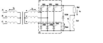
Three-phase thyristor voltage rectifier: examples of practical application
The three-phase thyristor rectifier is designed to convert the three-phase alternating voltage of the network into a constant regulated one. Let's consider examples of the practical application of a controlled thyristor converter.
The three-phase thyristor rectifier is designed to convert three-phase alternating mains voltage into adjustable constant voltage. The rectifier is one of the most common and classic power electronics products. We invite the reader to familiarize themselves with its internal structure and application options.
The general structure of a typical rectifier system is shown in Figure 1:
Figure 1. Three-phase thyristor current (voltage) rectifier
Three-phase alternating voltage is supplied to the primary winding of the network transformer TV through the network choke L. The voltage from the secondary winding is supplied to the controlled thyristor rectifier VS, assembled using a Larionov bridge circuit. The output voltage of the rectifier contains harmonics and filtering, for the suppression of which an L-shaped inductive-capacitive filter F is designed. In some cases, grounding of the negative wire (PE wire) is required.
Let's look at practical examples of using this device.
Example 1. Power distribution across three phases when supplying a single-phase load
Quite often there is a case when the heating element of an electric furnace is single-phase. With a large number of such furnaces in an enterprise and powering them with single-phase voltage, severe phase imbalances occur, which adversely affects other consumers and reduces the throughput of the electrical network. One solution could be to use a rectifier - when powering the load through a controlled rectifier, the power is evenly distributed across all three phases:
Figure 2. Powering a single-phase load from a three-phase rectifier
Example 2: DC Power Supply
The voltage rectifier can be used as a regulated high-power DC power supply. Such a source can be used for various applications: powering galvanic baths, charging batteries (thyristor charger), powering devices and substation automation with operational current (operating current cabinet SHOT). If it is necessary to implement a DC power system with protective grounding, galvanic isolation through a transformer is required.
Figure 3. DC Power Supply
Example 3: DC Motor Control
The classic application of a three-phase rectifier is to control the speed of a DC motor (DC):
Figure 4. DC Motor Speed Controller
To do this, you need two rectifiers: one powers the field winding, the second powers the armature winding. Currently, the DC electric drive is being intensively replaced by the AC variable frequency drive (VFD); However, for a number of reasons, DC motors are now widely used in industry and transport.
Figure 5. Three-phase thyristor controlled AC rectifier TVN
The Russian manufacturer of adjustable rectifiers is, which serially and on order produces a three-phase thyristor voltage rectifier TVN. The company's products are distinguished by a wide range of service functions, the presence of a complex of protections, stability, and reasonable weight and dimensions. The price of a thyristor rectifier is kept at a level affordable for most potential customers. Modern materials and components are used in production, for example, thyristor modules from Semikron, the world's leading manufacturer of power semiconductor devices. All products undergo careful control at all stages.
Basic technical data:
- rated output current 40, 80, 125, 160, 200, 250, 315, 400, 500, 630 A;
- output voltage – adjustable or stabilized (according to order);
- control system – microprocessor;
- output voltage and current stabilization modes;
- protection against short circuit, overload, overheating, loss or “sticking” of phases;
- data indication on a liquid crystal display;
- programming parameters from the push-button control panel;
- wide choice of control signals;
- degree of protection IP41 with the possibility of increasing to IP54;
- Upon request, additional equipment includes a smoothing choke, a mains filter, smoothing capacitors, and an analog output board.
Based on materials
Thyristor circuit of the regulator does not emit interference
The main difference between the circuit of the presented soldering iron power regulator and those presented above is the complete absence of radio interference into the electrical network, since all transient processes occur at a time when the voltage in the supply network is zero.
When starting to develop a temperature controller for a soldering iron, I proceeded from the following considerations. The circuit must be simple, easily repeatable, components must be cheap and available, high reliability, minimal dimensions, efficiency close to 100%, no radiated interference, and the possibility of upgrading.
The temperature controller circuit works as follows. The AC voltage from the supply network is rectified by the diode bridge VD1-VD4. From a sinusoidal signal, a constant voltage is obtained, varying in amplitude as half a sinusoid with a frequency of 100 Hz (diagram 1). Next, the current passes through the limiting resistor R1 to the zener diode VD6, where the voltage is limited in amplitude to 9 V, and has a different shape (diagram 2). The resulting pulses charge the electrolytic capacitor C1 through diode VD5, creating a supply voltage of about 9 V for microcircuits DD1 and DD2. R2 performs a protective function, limiting the maximum possible voltage on VD5 and VD6 to 22 V, and ensures the formation of a clock pulse for the operation of the circuit. From R1, the generated signal is supplied to the 5th and 6th pins of the 2OR-NOT element of the logical digital microcircuit DD1.1, which inverts the incoming signal and converts it into short rectangular pulses (diagram 3). From pin 4 of DD1, pulses are sent to pin 8 of D trigger DD2.1, operating in RS trigger mode. DD2.1, like DD1.1, performs the function of inverting and signal generation (Diagram 4).
Please note that the signals in diagram 2 and 4 are almost the same, and it seemed that the signal from R1 could be applied directly to pin 5 of DD2.1. But studies have shown that the signal after R1 contains a lot of interference coming from the supply network, and without double shaping the circuit did not work stably. And installing additional LC filters when there are free logic elements is not advisable.
The DD2.2 trigger is used to assemble a control circuit for the soldering iron temperature controller and it works as follows. Pin 3 of DD2.2 receives rectangular pulses from pin 13 of DD2.1, which with a positive edge overwrite at pin 1 of DD2.2 the level that is currently present at the D input of the microcircuit (pin 5). At pin 2 there is a signal of the opposite level. Let's consider the operation of DD2.2 in detail. Let's say at pin 2, logical one. Through resistors R4, R5, capacitor C2 will be charged to the supply voltage. When the first pulse with a positive drop arrives, 0 will appear at pin 2 and capacitor C2 will quickly discharge through the diode VD7. The next positive drop at pin 3 will set a logical one at pin 2 and through resistors R4, R5, capacitor C2 will begin to charge.
The charging time is determined by the time constant R5 and C2. The greater the value of R5, the longer it will take for C2 to charge. Until C2 is charged to half the supply voltage, there will be a logical zero at pin 5 and positive pulse drops at input 3 will not change the logical level at pin 2. As soon as the capacitor is charged, the process will repeat.
Thus, only the number of pulses specified by resistor R5 from the supply network will pass to the outputs of DD2.2, and most importantly, changes in these pulses will occur during the voltage transition in the supply network through zero. Hence the absence of interference from the operation of the temperature controller.
From pin 1 of the DD2.2 microcircuit, pulses are supplied to the DD1.2 inverter, which serves to eliminate the influence of the thyristor VS1 on the operation of DD2.2. Resistor R6 limits the control current of thyristor VS1. When a positive potential is applied to the control electrode VS1, the thyristor opens and voltage is applied to the soldering iron. The regulator allows you to adjust the power of the soldering iron from 50 to 99%. Although resistor R5 is variable, adjustment due to the operation of DD2.2 heating the soldering iron is carried out in steps. When R5 is equal to zero, 50% of the power is supplied (diagram 5), when turning at a certain angle it is already 66% (diagram 6), then 75% (diagram 7). Thus, the closer to the design power of the soldering iron, the smoother the adjustment works, which makes it easy to adjust the temperature of the soldering iron tip. For example, a 40 W soldering iron can be configured to run from 20 to 40 W.
Temperature controller design and details
All parts of the thyristor temperature controller are placed on a printed circuit board made of fiberglass. Since the circuit does not have galvanic isolation from the electrical network, the board is placed in a small plastic case of a former adapter with an electrical plug. A plastic handle is attached to the axis of the variable resistor R5. Around the handle on the regulator body, for the convenience of regulating the degree of heating of the soldering iron, there is a scale with conventional numbers.
The cord coming from the soldering iron is soldered directly to the printed circuit board. You can make the connection of the soldering iron detachable, then it will be possible to connect other soldering irons to the temperature controller. Surprisingly, the current consumed by the temperature controller control circuit does not exceed 2 mA. This is less than what the LED in the lighting circuit of the light switches consumes. Therefore, no special measures are required to ensure the temperature conditions of the device.
Microcircuits DD1 and DD2 are any 176 or 561 series. The Soviet thyristor KU103V can be replaced, for example, with a modern thyristor MCR100-6 or MCR100-8, designed for a switching current of up to 0.8 A. In this case, it will be possible to control the heating of a soldering iron with a power of up to 150 W. Diodes VD1-VD4 are any, designed for a reverse voltage of at least 300 V and a current of at least 0.5 A. IN4007 (Uob = 1000 V, I = 1 A) is perfect. Any pulse diodes VD5 and VD7. Any low-power zener diode VD6 with a stabilization voltage of about 9 V. Capacitors of any type. Any resistors, R1 with a power of 0.5 W.
The power regulator does not need to be adjusted. If the parts are in good condition and there are no installation errors, it will work immediately.
The circuit was developed many years ago, when computers and especially laser printers did not exist in nature, and therefore I made a drawing of the printed circuit board using old-fashioned technology on chart paper with a grid pitch of 2.5 mm. Then the drawing was glued with Moment glue onto thick paper, and the paper itself was glued to foil fiberglass. Next, holes were drilled on a homemade drilling machine and the paths of future conductors and contact pads for soldering parts were drawn by hand.
The drawing of the thyristor temperature controller has been preserved. Here is his photo. Initially, the rectifier diode bridge VD1-VD4 was made on a KTs407 microassembly, but after the microassembly was torn twice, it was replaced with four KD209 diodes.
Three-phase thyristor voltage rectifier: examples of practical application
The three-phase thyristor rectifier is designed to convert the three-phase alternating voltage of the network into a constant regulated one. Let's consider examples of the practical application of a controlled thyristor converter.
The three-phase thyristor rectifier is designed to convert three-phase alternating mains voltage into adjustable constant voltage. The rectifier is one of the most common and classic power electronics products. We invite the reader to familiarize themselves with its internal structure and application options.
The general structure of a typical rectifier system is shown in Figure 1:
Figure 1 Three-phase controlled current (voltage) rectifier
Three-phase alternating voltage is supplied to the primary winding of the network transformer TV through the network choke L. The voltage from the secondary winding is supplied to the controlled thyristor rectifier VS, assembled using a Larionov bridge circuit. The output voltage of the rectifier contains harmonics and filtering, for the suppression of which an L-shaped inductive-capacitive filter F is designed. In some cases, grounding of the negative wire (PE wire) is required. Let's look at practical examples of using this device.
Example 1. Power distribution across three phases when supplying a single-phase load
Quite often there is a case when the heating element of an electric furnace is single-phase. With a large number of such furnaces in an enterprise and powering them with single-phase voltage, severe phase imbalances occur, which adversely affects other consumers and reduces the throughput of the electrical network. One solution could be to use a rectifier - when powering the load through a controlled rectifier, the power is evenly distributed across all three phases:
Figure 2 Powering a single-phase load from a three-phase rectifier
Example 2 DC Power Supply
The voltage rectifier can be used as a regulated high-power DC power supply. Such a source can be used for various applications: powering galvanic baths, charging batteries (thyristor charger), powering devices and substation automation with operational current (operating current cabinet SHOT). If it is necessary to implement a DC power system with protective grounding, galvanic isolation through a transformer is required.
Figure 3 DC Power Supply
Example 3 DC Motor Control
The classic application of a three-phase rectifier is speed control of a DC motor (DC):
Figure 4 DC Motor Speed Controller
To do this, you need two rectifiers: one powers the field winding, the second powers the armature winding. Currently, the DC electric drive is being intensively replaced by the AC variable frequency drive (VFD); However, for a number of reasons, DC motors are now widely used in industry and transport.
The Russian manufacturer of adjustable rectifiers is, which serially and on order produces a three-phase thyristor voltage rectifier TVN. The company's products are distinguished by a wide range of service functions, the presence of a complex of protections, stability, and reasonable weight and dimensions. The price of a thyristor rectifier is kept at a level affordable for most potential customers. Modern materials and components are used in production, for example, thyristor modules from Semikron, the world's leading manufacturer of power semiconductor devices. All products undergo careful control at all stages.
Figure 5 Three-phase thyristor controlled AC rectifier TVN
Basic technical data:
- rated output current 40, 80, 125, 160, 200, 250, 315, 400, 500, 630, 800, 1000 A;
- output voltage – adjustable or stabilized (according to order);
- control system – microprocessor;
- output voltage and current stabilization modes;
- protection against short circuit, overload, overheating, loss or “sticking” of phases;
- data indication on a liquid crystal display;
- programming parameters from the push-button control panel;
- wide choice of control signals;
- degree of protection IP41 with the possibility of increasing to IP54;
- Upon request, additional equipment includes a smoothing choke, a mains filter, smoothing capacitors, and an analog output board.
How to reduce the level of interference from thyristor regulators
To reduce interference emitted by thyristor power regulators into the electrical network, ferrite filters are used, which are a ferrite ring with wound turns of wire. Such ferrite filters can be found in all switching power supplies for computers, televisions and other products. An effective, noise-suppressing ferrite filter can be retrofitted to any thyristor regulator. It is enough to pass the wire connecting to the electrical network through the ferrite ring.
The ferrite filter must be installed as close as possible to the source of interference, that is, to the installation site of the thyristor. The ferrite filter can be placed both inside the device body and on its outside. The more turns, the better the ferrite filter will suppress interference, but simply threading the power cable through the ring is sufficient.
The ferrite ring can be taken from the interface wires of computer equipment, monitors, printers, scanners. If you pay attention to the wire connecting the computer system unit to the monitor or printer, you will notice a cylindrical thickening of insulation on the wire. In this place there is a ferrite filter for high-frequency interference.
It is enough to cut the plastic insulation with a knife and remove the ferrite ring. Surely you or someone you know has an unnecessary interface cable from an inkjet printer or an old CRT monitor.