What is an asynchronous motor?
Before moving on to the model, algorithms and control systems of an electric drive, you need to know exactly what it is. This makes it possible to identify moments in its circuit that can be used to organize a smooth change in key characteristics (frequency/rotation speed, voltage). Accordingly, it is possible to determine the parameters of the controller, develop technological maps for its placement in the cabinet and maintenance.
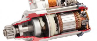
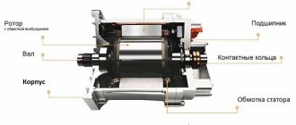
The operation of any asynchronous motor is based on the excitation of a magnetic field on the contact windings when electricity is supplied from the control cabinet. It occurs on the stator - the stationary part of the engine, which consists of a ring core (magnetic core) assembled from individual metal plates. Each of them has concentric grooves on the inside of the ring, which when combined form longitudinal grooves. They are used to wind the wire that forms the basis of the stator winding.
Also, an asynchronous motor has a moving part - a rotor combined with a drive shaft. It also has a plate core with grooves, but on the outside. Instead of wire, copper rods are used, which are closed at the edges by plates (this version of the engine is called a squirrel-cage motor).
Due to the fact that the rotation frequencies of the magnetic fields of the stator and rotor are different, an electric current is induced in the windings of the latter due to induction. This in turn induces an electromagnetic force that causes the rotor to move (rotate). The frequency difference is usually called glide. Its value is about 2...10%.
Vector asynchronous motor control, application and methods
To understand what “vector” control is, it is the reaction of a turning device with the so-called “spatial” vector, which rotates at the frequency of the engine sphere. And in order to better understand all its functions, it is advisable to review the article and find the necessary information.
An asynchronous motor is a motor of variable flow, where the energy in the stator windings creates a rotating field of magnets. Such a field induces currents in the winding of the rotor, affects the operating currents, attracting the rotor into operation.
However, in order for the rotating magnetic sphere of the stator to induce currents in a working rotor, the rotor in the hardware spinning is forced to be slightly behind the spinning of the stator. Consequently, in a non-synchronous motor, the speed of rotor circulation is constantly approximately the same as the speed of rotation of the magnetic field (which is caused by pulses of unstable current, which is why the motor is powered). When the rotor's departure from the moving magnetic field of the stator is greater (rolling), a heavy load will therefore be created on the motor.
A lack of synchronism between the torsion of the rotor and the magnets in the stator is a normal feature for an unstable motor, which is where its name comes from. The rotating magnets in the stator are formed using coils powered by flows that are in phase.
Naturally, for the sake of this mission, a 3-phase unstable current is adapted. There are also single-phase asynchronous motors, in which the progression of phases among the currents in the windings is formed by connecting all sorts of resistances in the windings. To carry out high-quality adjustment of the angular speed of rotation of the rotor, and also the rotation factor on the shaft of current brushless motors, they use either vector or scalar control by an electronic drive.
Vector control is a method of controlling brushless motors of unstable current, which allows you to independently and, in principle, inertia-free coordinate the speed of rotation and the torque on the electric motor shaft.
The key idea behind vectorial movement is to check not only the magnitude and impulse of the feeding force, but also the phase. In other words, the value and angle of the plastic vector are tested.
Advantages of vector control:
- highest reliability of speed control;
- smooth start of movement and smooth motor handling across the entire frequency spectrum;
- rapid suppression when changing the load: when the overload changes, there is absolutely no change in speed;
- enhanced range of management and punctuality of regulation;
- heating leaks and magnetization are reduced, and the efficiency of the electric motor increases.
The disadvantages of vector control include:
- the need to adjust motor parameters;
- huge swings of rapidity under long-term load;
- high computational complexity.
The following methods of adjusting an asynchronous motor are used: ·
- rheostat - modification of the transmission of rotation of an asynchronous motor with a wound rotor by replacing the resistance of the rheostat in the rotor circuits, and in addition, this makes the starting torque larger and increases the decisive slip; ·
- frequency - reversal of the circulation pulses of an asynchronous motor by changing the conductivity of the flow in the supply voltage, due to which this helps to modify the repeatability of the rotation of the stator field. The motor is introduced through a conductive reformer;
- reconnection of the windings using a “star” to “triangle” circuit during engine startup, which creates a threefold reduction in the starting currents in the windings, but it also helps to reduce the torque; ·
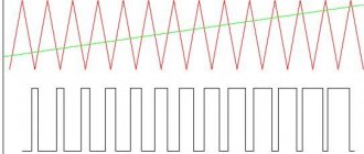
- pulsating feed - power supply of a specific option (for example, sawtooth); · the establishment of an auxiliary EMF is harmonious or oppositely directed with the slip frequency into the secondary circuit; ·
- changing the number of poles, if such a reversal is reasonably foreseen (only on squirrel-cage rotors);
- replacement of the amplitude of the supply voltage if only the amplitude (or influencing value) of the swirling flow is modified. Further, the control and excitation voltage vectors remain perpendicular (autotransformer starting); ·
- phase control is characterized by the fact that the reversal of the rotor spinning impulses is created by changing the advancement of the phases between the vectors of excitation and control forces. ·
- amplitude-phase reception covers the two described methods; ·
- investment in the reactor stator power supply apparatus; ·
- inductive reaction on a wound-rotor motor.
Electric scheme
The basis of the circuit is the outline of the control of magnetic flux coupling and circumstances together with the evaluation unit, which can be used in a variety of ways. This means that the outer speed control loop is highly unified and generates speed control signals to adjust the M* factor and magnetic flux linkage* (via the flux control source). The speed of the motor can be measured using a meter (speed / position) or can be done through an assessment, which allows you to create sensorless control.
Classification of vector control technologies
Only the most famous control technologies are discussed here. The discussed methods for controlling the factor are presented for control systems for asynchronous motors and synchronous motors with long-term magnets with sinusoidal return EMF.
Most often, torque control methods are divided into the following types:
- Linear (PI, PID) regulators;
- Nonlinear (hysteresis) regulators.
- No return communication.
- There is feedback.
- In an established order.
Vector regulation details
To get rid of the disadvantages, back in 1971, Siemens engineers recommended using vector guidance in the tool, during which control is executed with feedback of values in the flow. The initial arrangements of the vectorial direction contained detectors in the instruments. Now the approach to this method is quite different:
- An exact sample of the motor allows one to analyze the speed of rotor circulation and the gross torque from the initial stage of the existing phase currents (from the repeatability and number of currents in the stator windings).
This more conscious approach helps to create an independent and almost inertia-free coordination of both the shaft moment and the speed of shaft circulation on the pressure force, since flow phases are provided during control. Some more executive systems of vector control are equipped with fundamental methods of feedback on the force of movement, and control systems without speed meters are called sensorless.
In connection with the areas of use of any of the electric drives, their vector control technique will have to have its own characteristics, as well as some required level of accuracy for control. If the conditions for actual speed regulation allow a slope of 1.5%, and the scale of regulation is no higher than 1 to 100, then the sensorless design will be absolutely perfect. When accuracy of speed adjustment with a shift of no more than 0.2% is required, and the spectrum is combined to 1 in 10,000, then the existence of a feedback connection via the speed meter on the shaft is important.
The presence of the rapidity connector in the vector control examples allows the start to be perfectly coordinated even at low conductivities up to 1 Hz. Well, vectorial control delivers the benefits it deserves. The highest precision in regulating the speed of rotation of the rotor (and without a speed meter on the device) in conditions of movably replaceable overload on the shaft, so jerks are not expected. Easy and direct shaft handling at low speeds.
High efficiency for low losses in the normal environment of these power supplies. Vector control also has its disadvantages. Computational entanglement. The need to create initial parameters (for example, a controlled drive).
For a quantitative electronic drive, vectorial control is not suitable; here, scalar control will be preferably used.
The result occurs due to the phenomenon of circulation currents in the cylinder. Since it seems in the law of electromagnetic induction discovered by Faraday, to replace the flux of magnets with an isolated silhouette in the middle is the emf or voltage. This meaning, applied to a copper cylinder, instantly activates the origin of current in the cylinder.
Also, this current also organizes its own, counter electromagnetic flow, concentrated directly to the other side from the replacement of the magnet flow:
- The high-frequency current appearing in an isolated shorting circuit has a similar side of motion that the magnetic field it creates acts as a resistance to this change in the magnetic flux that was activated by this current.
- The closed outline resists the change in magnetic flow in the instrument.
- If you quickly place a magnet on a copper cylinder, then a bold modification of the magnetic flow occurs, so similar counter-currents will flow in the cylinder, then the magnetic sphere in it at the beginning of movement will be equally zero: the magnetic field of the adjacent magnet will be absolutely compensated by the magnetic currents of the cylinder.
When the magnet is presented and held, the energy in the cylinder, due to the presence of the functional resistance of copper, will slowly decrease, and the field of the cylinder, organized with flows, will disappear: the magnetic flow of a long-term magnet will “break out” inside the cylinder, as if the cylinder does not exist at all. You just need to try to hide the magnet, then the cylinder will respond again - only now it will perhaps be able to independently “recreate” the disappearing electromagnetic flux in the middle of the body, then at first it will resist replacing the magnetic flux, in such a situation and its disappearance.
What does it mean to “recreate electromagnetic motion”?
Therefore, it is known that for a certain period of time, the wind cylinder can be considered a symbolic “continuous magnet” - a turbulent current moves in the unit, causing a magnetic field (with this type, superconductors “hang” in a magnetic field). The rotor of an asynchronous motor, with a “squirrel cage” appearance, with a current from one of the “frames” of the squirrel cage responds to an increase in the external magnetic field.
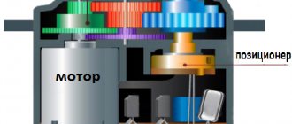
Vector sensor design of discontinuous motor guidance
The caretaker contains evidence from the rotor location sensor, and leaking stator fluids in the axes, . At the end of the contemplator is the location of the rotor “magnet”, the actual angle of the contemplative flux clutch of the rotor. In the remaining ones, the design is absolutely similar to a similar scheme assigned to a continuous tool, only the d, q axes are rewritten to x, y, and the x axis is assigned a flux assignment that can be assisted by a “magnet” in the rotor. In addition, an “s” indicator has been added for many values to make it clear that only the value provided places the position towards the stator, instead of the rotor.
What happens? The rotor magnet always slides due to its location on the rotor on the edge of the y-axis. The stronger the current, the more powerful the sliding. The viewer in the present period calculates the location of a given magnet and “adjusts” the x, y axes all the time forward tangent to the d, q axes (the location of the rotor). The x-axis constantly fits the current location of the flux linkage in the rotor - the location of the "magnet". The x, y axes always move (in motor effort) a little faster than the rotor is spinning, eliminating slipping.
The energy in the rotor, if measured or simulated, comes out sinusoidal. These devices are exclusively modified without the conduction of stator flows, but with the presence of pulse slips, that is, infinitely slowly. When the industrial intermittent stator is 50 Hz, then when the load mode is switched on, the harmonic in the rotor is small hertz values.
Why is vector control with an asynchronous engine better than scalar control?
Scalar guidance is if the force of the established conductivity and amplitude is adapted to two-speed engines - for example, 380V 50Hz. And due to overload for the rotors, this does not affect the operation in any way - without current regulators and so on... The radio frequency of the force and this amplitude are simply set - scalar values, and the energy and flows in the engine are independently set, as they need.
In the created system of the motor product, vectorial control is indistinguishable from scalar control - vector control will undoubtedly also be presented at the same 380V, 50Hz even under normal load. However, transitional types are excluded... if it is necessary to quickly turn on an electric motor with a given torque, if it is necessary to develop a diagram, when there is a pulsating load, when it is necessary to generate heat, the electric generator regulation with the required degree of strength - scalar regulation either cannot perform such data, or does so with very poor , slow transient actions, which can also “knock out the protection” of reconfiguring pulses due to excess current or the force of the long-term current link (the engine swings and can jump into the power generator, for which the frequency device may not be prepared).
In the vector structure, “controlling”. The beginning of the movement is set by itself, and so is the flow. It is allowed to narrow it at the right stage so as not to exceed the laws of protection. It is possible to adjust and boost currents if it is immediately necessary to produce a significantly more powerful torque. It is possible to coordinate not only the start of the motor, but also the flow (x-axis current): when the overload on the motor is not great, then there is no reason to maintain the current in the rotor (to create an “optimal mode” magnet) - it is possible to relax it, making less loss.
It is necessary to regulate haste with the speed regulator with increasing punctuality and speed. It is important to use a non-simultaneous drive as a traction drive, giving it the required traction torque. In short, for heavy efforts with active motor output, vectorial control by an asynchronous motor is indispensable.
In addition, there are characteristic features of the vector control of an asynchronous mover from a synchronous one.
The first is a value measuring device. When, in order to carry out a simultaneous drive, it is important to understand the unconditional position of the rotor in order to know the position of the magnet, then such information is not needed in an asynchronous drive. The rotor does not have a certain defined pole system, the “magnet” slides there non-stop, but you can look at the control circuits for the rotor flux coupling, and there is also no need to reduce the position: only the harmonic of the rotor circulation is included in the switching methods. Therefore, it is possible to save money on the meter: an ordinary incremental encoder is sufficient to observe the ionization of rotation (possibly a tachogenerator), perfect position meters are not important.
The next step is motion control in an asynchronous motor apparatus. In a continuous machine with long-lasting magnets, the flow is not adjusted, which eliminates the highest frequency of motor rotation: it will not take force from the inverter. In a multi-time engine, sometimes this happens... you simply need to reduce the order on the x-axis and move on! The largest fluctuation is not limited. In exactly the same way, there are sensorless methods of vector control of an asynchronous motor, which evaluate the rotor flux angle as a non-working warning of the position (or speed) meter of the rotor shaft.
Literally the same as in continuous instruments, in the system of operability of such methods there are difficulties with low oscillations of the rotor rotation, in which the EMF of the motor is small. If with industrial asynchronous engines the work is done cheaper by installing a duralumin cage, then in traction, in which large-scale dimensions are more needed, the opposite will be true; a copper cylinder can be recycled.
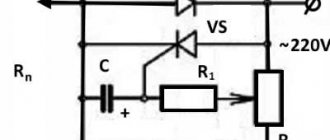
Thyristor control
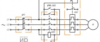
To control an asynchronous motor, it is important to use thyristors in combination with relay-contactor units. They are adapted as powerful ingredients and are part of the stator circuit; relay-contactor circuit breakers are connected to the control circuit. Thyristors are used as power connectors, it is allowed to apply force to the stator at startup to zero according to the common adverb, reduce the energy and moments of the box, implement effective braking or step-by-step operation.
To start the motor, it is connected to the interacting switch QF, presses the SB1 “Start” button, and as a result, contactors KM1 and KM2 are connected. On the moving cathodes of the thyristors, impulses are given, closed at 60 relative forces. A low power is applied to the motor stator, which makes the starting current lower and the starting torque as well.
How can you control the engine speed?
Obviously, the motor in normal operation from the mains (electrical cabinet) has a standard speed/rotation frequency. This limits its direct use, forcing the use of various gear mechanisms to reduce the frequency to the required one. But even then, there is no way to dynamically change the speed, and with it, power, flow, since the frequencies at the output of the engine and gearbox still remain fixed. To expand the existing framework, different control methods are used (frequency, pulse, phase, etc.), which can be divided into two large groups:
- Scalar. Typically used on drive motors of compressor, fan, pump and other mechanisms where monitoring of rotation speed or any other parameter associated with sensors is required,
- Vector. This is an advanced concept that provides separate, independent control, torque and magnetic flux control. The rotor current coupling is maintained at a constant level, which allows maintaining the maximum torque value.
Asynchronous motor control
The difference between scalar and vector control lies precisely in the possibility of excitation (flow) control. In fact, it is represented as a DC motor having windings independent of each other. This approach allows you to create a similar mathematical model of the controller operating system.
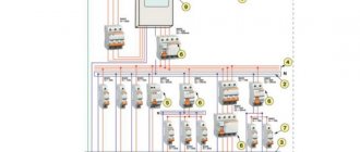
Schematic diagram
The circuit shown in Fig. 2 consists of: control device D2 (microcontroller PIC16F628-20/P is used, operating at a frequency of 20 MHz), control buttons “Start” (SA1), “Stop” (SA2), increase and decrease buttons frequencies SA3 and SA4, respectively, binary-seven-segment decoder D1, LED matrices HG1 and HG2, braking unit VT9, VT10, K1.
The power circuit uses a three-phase bridge driver D4 IR2130 from International Rectifier, which has three outputs for controlling the lower bridge switches and three outputs for switches with a floating control potential.
Rice. 2. Schematic diagram of microcontroller control of an asynchronous three-phase motor.
Rice. 2. Schematic diagram of microcontroller control of an asynchronous three-phase motor (continued).
This microcircuit has a current protection system, which in case of overload turns off all switches and also prevents the simultaneous opening of the upper and lower transistors, thereby preventing the flow of through currents. To reset the protection, you must set all units at the inputs HNx, LNx. IRF740 MOS transistors are used as power switches.
The overload circuit consists of a current sensor R10, a voltage divider R7R9, which allows you to accurately set the protection operation current, and an integrating circuit R6C3, which prevents false operation of the current protection at switching times. The protection response voltage is 0.5 V at the ITRP input (D4).
After the protection is triggered, log “0” appears at the FAULT output (open collector), the HL1 LED lights up and all power switches are closed.
To more quickly discharge the gate capacitances of power transistors, diodes can be installed parallel to the resistors included in the gate circuit in the opposite direction. The engine must be turned on in a star circuit.
The power supply consists of powerful diodes VD11-VD14, a current-limiting resistor R20, a filter capacitance C10, a capacitance C11 that prevents surges that occur during switching on parasitic inductances of the circuit, as well as a low-power transformer T1, a 15 V voltage regulator D5 for powering the driver circuit, stabilizer voltage 5 V D3 to power the microcontroller and indication circuit.
When using a more powerful motor, instead of IRF740 transistors, you can use IGBT transistors of the types IRGBC20KD2-S, IRGBC30KD2-S, while the diodes VD7-VD10, VD15, VD16 should be unsoldered. Capacitor C11 type K78-2 for a voltage of 600...1000 V. Instead of VD1-VD6, it is advisable to use ultra-fast diodes of type 10DF6, and reduce capacitances C15-C17 to 2.2...4.7 μF, which should be designed for a voltage of 50 V. Transformer T1 0.5.2 W from a calculator with a rewound secondary winding. The winding is wound with wire 00.2 and should produce 19.20 V.
Forms and diagram of vector control
All existing vector engine control systems can be divided into two groups:
- Sensor The engine control unit has speed feedback with it, using the corresponding sensors located on the shaft,
- Sensorless. These are systems that operate without speed sensors on the main shaft.
Sensor systems are more complex, since the control accuracy is 1:10000. Sensorless systems operate at a level of no more than 1:100. All frequency generators, taking into account the level of interference generated, are installed in central or separate cabinets.
If we present all of the above as a visual diagram, we get something like this:
Here you can see such key components of the control system as:
- AD is actually an asynchronous motor (object of control),
- BRP – logical block of regulators for equation variables,
- BVP is a logical block responsible for calculations based on variables,
- BZP is a block that specifies the values of variables,
- DS – speed sensor on the motor shaft,
- AIN PWM – pulse amplitude/pulse width modulation unit.
What is shown in the diagram as blocks is, in practice, just parametric elements of the control circuit, which is implemented on a microcontroller. Accordingly, the controller itself and accompanying actuators are mounted in an electrical cabinet. For proper installation, a technological map is being developed.
Review of options for direct torque control of asynchronous electric motors - part 1
Unlike the FOC control method, which contains a pulse width modulation unit and a current loop, DTC and DSC contain relay controllers that operate directly on stator flux and torque without the use of internal current loops.
Since the appearance of these two works, researchers in the field of electric drive have turned their attention to improving new control methods and developing improved methods based on the same principle [4-8].
Most of the work was aimed at overcoming the main disadvantages of DTC and DSC:
- Large range of fluctuations in the values of the electromagnetic torque and the amplitude of the stator flux vector (“ripple” or “ripple” in foreign literature).
- Inconstancy of the switching frequency of the inverter keys, which negatively affects the thermal state of the keys.
- A large value of the amplitude of the stator current when the amplitude of the stator flux vector changes, in particular during startup.
If the third drawback can be eliminated by introducing feedback on the amplitude of the stator current or limiting the rate of increase in the amplitude of the stator flux vector, then the first and second drawbacks are difficult to overcome.
In foreign literature, many methods have been proposed for direct control of the torque and flow of asynchronous electric motors, which can be usefully divided into groups:
- Closed-loop control methods based on an integrated representation of the electric motor model (ISC) [8, 9].
- Open-loop methods based on calculating the optimal duration of the voltage vector pulse based on a linearized engine model [10, 11].
- Open-loop methods based on calculating set values, components of the stator voltage vector, contributing to the achievement of the stator flux amplitude and electromagnetic torque of set values after one sampling period (Deadbeat DTC) [12, 13].
- Closed-loop methods for controlling the electromagnetic torque and amplitude of the stator flux vector, based on a model of the electric motor in a coordinate system associated with the stator flux vector (DTC-SVM) [14-16].
- Methods for increasing the switching frequency of inverter switches by introducing a high-frequency interference signal into error signals for controlling the torque and amplitude of the stator flux vector (Dithering DTC) [17, 18].
- Methods based on DTC and fuzzy logic used to control the width of voltage pulses (Fuzzy based DTC) [19].
- Methods based on fuzzy logic, completely replacing the original DTC system (Fuzzy DTC) [20-22].
- Methods for controlling the electromagnetic torque and amplitude of the stator flux vector based on artificial neural networks (ANNDTC) [21, 22].
Frequency controller management
Modern current/voltage frequency converters operate in both scalar and vector versions, using parametric mathematical models implemented in the program code of the built-in microcontroller. Electronic frequency drives operate on thyristor bridge circuits and include the following main components:
- Rectifier - a thyristor or transistor bridge that converts alternating current into direct current,
- An inverter is an AIM/PWM unit that operates on the reverse principle, that is, converting direct current into alternating current.
Since such a transition in one way or another affects the shape of the output voltage graph, the block controller/frequency driver can use special EMC filters in the inductor circuit. The latter are used to reduce the intensity of electromagnetic interference.
Frequency controller management
The central controller provides parametric control of the circuit, as well as auxiliary tasks, for example, condition diagnostics, overload protection, etc. The frequency generator itself is usually mounted in a separate cabinet to reduce electromagnetic interference to the equipment.
In general, vector control, organized on a modern controller and frequency converter, allows for smooth regulation of key quantities, as well as side parameters of equipment operation. Due to the presence of electromagnetic interference during operation, frequency units are usually located separately from the main electrical cabinet.