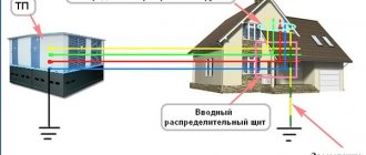
Portable grounding is a protective device designed to ensure safe operation in electrical installations. A grounding device is installed in de-energized areas of the installation where repair work will be carried out. This is necessary in order to prevent accidental supply of voltage to the area removed for repair and to eliminate the occurrence of induced voltage. If voltage is accidentally applied to the prepared area, a short circuit occurs and the protective equipment breaks the power circuit, thereby protecting repairmen from electric shock. During a short circuit, the voltage tends to zero and the current to infinity. Below we will look at the device, purpose and scope of portable grounding.
What is portable grounding and its purpose
Portable grounding (PG) is a special product designed for grounding individual sections of an electrical installation that do not have stationary grounding blades. The main function of the PP is to ensure the safety of workers when carrying out repair work.
This is what portable grounding looks like
Installing a PZ allows you to protect personnel from exposure to electric current due to erroneous, spontaneous supply of voltage, as well as as a result of the formation of induced voltage. When voltage is applied to a grounded section of the electrical network, a short circuit current is generated, which leads to the launch of protection, followed by disconnection of the voltage source.
Grounding for overhead lines
Portable grounding for overhead lines is designed to protect workers from high voltage damage by grounding a section of overhead lines from erroneously supplied or induced voltage from adjacent lines. Grounding connections for overhead lines consist of phase clamps or clamps, short-circuiting/grounding flexible conductors, insulating grounding rods (insulating ropes), as well as grounding clamps. For various types of work, portable grounding can be produced as single-phase or three-phase (for 0.4 kV overhead lines - five-phase), and also, in some cases, the number of phases can be more than 3.
On overhead lines, two main types of grounding are used - with a solid insulating rod and a composite rod consisting of metal conductive links and an insulating part. Grounding connections for overhead lines with a solid insulating rod are universal and most common. Mainly used when working from towers and lifts, as well as when using claws and manholes. Grounding connections with metal conductive links are used on overhead lines of high voltage classes when working from a crossarm. Recently, such groundings have begun to be used on 6-10 kV lines for installation from the ground. The use of metal conductive links is caused by the need to reduce the weight of the grounding as a whole with a long rod length. The combination of a structural and conductive grounding element makes it possible to reduce the weight load on the worker’s hands to an acceptable value. For this reason, grounding for overhead lines with metal conductive links, as a rule, is made single-phase.
Device
There are two main options for using PP. The first option is intended for use in switchgears, and the second - on overhead power lines. Grounding can be made in single-phase or three-phase design.
The PZ can be made in three design variations: rod, rod with a metal link (ZPL-10) and rodless (ZPP-15).
Portable grounding type ZLP-10
The design of the product consists of the following elements:
- flexible conductor (copper or aluminum);
- fastening clips;
- tips (clamps);
- dielectric rod.
The rodless design of the PZ is usually used for use in complete switchgears.
Example of a rodless PZ design
To simultaneously short-circuit three phases through a single grounding conductor, a three-phase grounding conductor is used.
Single-phase version of portable grounding is intended for separate connection of phases to the grounding loop. Used on power lines with a voltage level of more than 110 kV. This is due to the significant distance from the grounding bus to the phase wires and the phase-to-phase span.
The flexible conductor may be coated with transparent insulation. It can be made of aluminum or copper wires. Using clamps, the PZ is attached to live parts and to the ground loop. The device of phase clamps can be made in the form of clamps and copper tips. The clamps are tightened using an insulating rod, with the help of which the minimum permissible distance to live parts is achieved.
What to do if there is no standard protective grounding
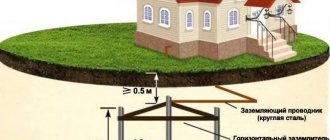
If work is carried out on an ungrounded (standard) electrical installation, it is necessary to create a temporary grounding loop. For this purpose, the same triangle is organized in accordance with the rules for organizing a protective grounding system. A portable grounding connection is connected to it.
The ground electrode is organized using metal pins, profiles (they are driven in with a sledgehammer), or gimlets. Such devices must have a device for removing them from the ground after completion of work.
Another option for easy installation is a return hammer ground electrode. With its help, you can easily immerse the rod in the ground and remove it back.
Installation of portable grounding on a temporary circuit is carried out according to the same rules as on a stationary protective grounding bus.
Requirements
There are many requirements for portable grounding systems. Among the main ones, thermal and dynamic stability with respect to short circuit currents stands out. The design of products should ensure ease of use.
The shorting conductors must withstand environmental influences ranging from -45 to +45 degrees. The cross-sections of the grounding conductors must correspond to the voltage levels. In electrical installations up to 1 kV, 16 square millimeters are used, and at voltages above 1 kV - 25. At a voltage level of more than six kilovolts, the cross-section of the conductors can reach one hundred and twenty square millimeters.
If there are different voltage levels in electrical installations, it is permitted to use portable grounding with the largest required cross-section to service all electrical equipment.
The product package must include technical documentation. The clamp can be fastened to the conductor cores by bolting, welding, pressing or using pressure plates. The clamp must ensure reliable contact at the application site. Insulating structures must be made of dielectric materials.
It is prohibited to use protective shells on conductive elements of the ground electrode, which interfere with visual inspection of their integrity. To insulate wires, it is allowed to use only a transparent sheath.
Grounding for switchgear
Portable grounding for switchgear is intended to protect workers from high voltage damage by grounding a section of the switchgear from erroneously supplied or induced voltage from neighboring circuits. Having an identical design, grounding connections for switchgear differ in the method of installation in the switchgear: phase clamps are installed on conductive busbars, on special ball or cylindrical tips, or instead of fuses. Various locations for installing grounding in the switchgear are determined by the work regulations and the design features of the electrical installations being serviced.
Calculation of cross-section for PZ
The minimum cross-section of the grounding conductor is determined by the formula:
Smin = (Ik.z.*√t)/C
- I short circuit – maximum current value during a short circuit;
- √t – the longest response time of the main protective devices to disconnect a short circuit;
- C is the calculated coefficient, which reflects the change in the resistance of the material under the influence of heat.
The longest time to disconnect a short circuit is taken to be the total value of the following indicators:
- activation time of the main protection;
- response time of automatic restart (reclose);
- duration of machine shutdown.
The calculated value of I short circuit depends on the type of neutral of the electrical network. With a grounded neutral, the value of single-phase short circuit current is used, with an isolated neutral - three-phase.
Requirements for electric shock protection systems
Portable protection systems are reliable to use. They do not cause installation problems and create a strong and reliable barrier that prevents the risk to the health and life of people working with electrical networks.
This equipment must have the following parameters:
Impeccable dynamic strength. The clamps must not break due to the force applied by the electricians.
Thermal resistance to grounding-induced short circuit current. None of the elements of the device should be subject to burning, melting, or overheating as a result of exposure to ultra-high temperatures. Otherwise, burnt and melted ends may cause high voltage.
Conductors in portable grounding are connected by welding or crimping. Conductors can also be connected with bolts. In this case, the fastening must be duplicated for strength using hard solder.
It is prohibited to use soldered grounding that is not additionally secured by other elements, since the solder may melt. Copper wires used in portable grounding do not have insulation precisely for the reason that it involves overheating when a short circuit occurs (the insulating materials melt under the influence of ultra-high temperatures).
Installation and removal of portable grounding
The process of applying and removing grounding is identical for all voltage levels. There are differences only in the number of people performing these operations. In electrical installations up to 1 kV, installation and removal of the ground electrode is carried out individually, and at voltages above 1 kV, the procedure is performed by two people. One person acts as a controller, and the second is an executor.
Process of installation and installation of PZ
Sequence of actions when installing the software:
- Make sure the integrity of the installed grounding;
- Check that there is no voltage at the electrical installation that must be grounded;
- Connect the clamp PZ to the ground loop;
- Place grounding conductors on current-carrying elements.
Operations for removing portable grounding are carried out in the reverse order. All actions must be carried out using dielectric gloves and rods, as well as personal protective equipment. In electrical installations up to 1 kV, only insulating gloves may be used. When the voltage of current-carrying elements is more than 1000 V, the simultaneous use of gloves and rods is required.
Checking the absence of voltage in a section of the distribution installation is carried out with a voltage indicator.
Parallel installation of portable ground electrodes in an electrical network with a voltage of more than six thousand volts is allowed. This is due to the fact that the required wire cross-sections reach significant values. And it leads to an increase in the mass and size of the PZ, which entails difficulties in their operation.
Grounding locations
Portable grounding must be applied to the current-carrying parts of all phases of the electrical installation section that is disconnected for work on all sides from which voltage can be supplied, including due to reverse transformation. It is sufficient to apply one ground connection on each side. These grounds can be separated from live parts or equipment on which work is performed by disconnected disconnectors, circuit breakers, circuit breakers, or removed fuses.
The application of grounding directly to the current-carrying parts on which work is performed is required when these parts may be under induced voltage (potential) or voltage from an extraneous source of dangerous magnitude may be applied to them. Places for applying grounding must be selected so that the grounding is separated by a visible gap from live parts that are energized. When using portable groundings, their installation sites must be at such a distance from live parts that remain energized that the application of groundings is safe. When working on busbars, at least one grounding must be applied to them. In closed switchgears, portable grounding connections must be applied to live parts in designated locations. These areas must be cleared of paint and bordered with black stripes.
In electrical installations whose design is such that applying grounding is dangerous or impossible, additional safety measures must be taken when preparing the workplace to prevent accidental supply of voltage to the work site. These measures include:
- locking the disconnector drive with a padlock
- enclosing the knives or upper contacts of the specified devices with rubber caps or hard linings made of insulating material
Tests
To confirm compliance with GOST requirements, portable grounding systems are subjected to the following types of tests:
- acceptance (during the initial check for compliance with established standards);
- periodic (permissible once every five years);
- standard (with design changes).
Portable groundings are considered suitable for use if the following measures are successfully completed:
1. Visual inspection of the integrity of all structural elements.
Includes inspection of clamps, conductor cores, insulating rod, restrictive ring on the rod, anti-corrosion coating, protective insulation and technical documentation.
2. Climatic tests.
The procedure is carried out at negative and positive temperatures. Its value should reach forty-five degrees Celsius, respectively, below and above zero. Portable grounding is exposed to temperature for two hours. If there are no signs of destruction of the protective insulation and plastic elements, the product is considered suitable for use.
3. Determination of the mechanical strength of rods.
This experiment is intended to measure the bending of the PZ rod. The permissible deflection deviation is ten percent relative to the insulating length of the rod used for electrical installations with voltages up to 220 kV. For higher voltage levels, a twenty percent deviation is allowed.
To carry out the test, the rod is fixed in a horizontal plane. Securing the end of the rod and the place where the restrictive ring fits. Use a metal ruler to set the level of the rod axis. And according to it, the amount of deflection is calculated.
4. Checking the cross-section of the cores.
To establish the actual cross-section of the portable grounding, it is disassembled into strands. Their number is recorded and the number of conductors in one strand is counted. The diameter of the conductor is measured to determine its cross-section. The resulting calculated value is multiplied by the number of conductors in the strand and by the number of strands.
5. Measurement of thermal and dynamic resistance.
The experiment consists of passing through the finished product the appropriate value of short circuit current from laboratory current sources. The current flow continues until the prototype is completely destroyed. If within three seconds no mechanical damage or cores being thrown from the installation sites were observed, then the sample satisfies thermal and dynamic resistance.
6. Determination of the level of contact resistance.
A microohmmeter is used to measure the resistance at the point where the conductors are connected to the clamp. This indicator should not exceed 600 μOhm.
7. Electrical checks of insulating elements.
The insulating parts of portable grounding are subjected to high-voltage tests.
During operation, mechanical tests of grounding wires are not performed. Rods with metal elements are subject to electrical testing. This procedure is performed every two years.
The product is removed from service if the following defects are found:
- disruption of the connection between the clamp and the conductor;
- traces of metal melting or destruction of grounding conductors;
- the presence of more than five percent breakage of conductor cores.
Calculation of cable cross-section during installation
The cross-section of the portable grounding cable is selected based on the maximum possible response current of the protection of an electrical installation or overhead line, taking into account the response time of the protection.
In practice, it is customary to use a cable with a cross-section of at least 16 mm2 to protect electrical installations with voltages up to 1000 V, and 25 mm2 for those above 1000 V. The maximum cross-section of the grounding cable is 95 mm2. If it is necessary to use grounding with a large cross-section or if the required one is not available, you can use several grounding devices of a smaller cross-section installed in parallel. The total area of several grounding conductors must be equal to or greater than the required one.
To determine the cross-section of the cable, it is necessary to determine the cross-section of the elementary core by its diameter and multiply by the total number of cores. It is impossible to determine the cable cross-section by directly measuring its diameter, since due to the loose fit of the individual cores, the resulting value will be greatly overestimated and will not correspond to the real one .
Equipment and markings
Depending on the design of the product, the kit includes:
- portable grounding, assembled or disassembled;
- insulating rods;
- covers;
- technical certificate.
All portable grounding connections must be marked. Which reflects the following information:
- trademark or name of the enterprise that produced the PZ;
- release date and product type;
- core section;
- operating voltage level.
Grounding power lines on poles
Portable grounding intended for power lines differs from “ground” options in the presence of long insulated rods. In addition, the working ends are not equipped with screw clamps, but with gripping hooks with clamps.
Since such work is usually carried out in a field where there is no standard protective grounding, portable grounding electrodes are used. They are usually included in the kit.
Taking into account the absence of screw terminals, and, as a result, less reliable contact with the current-carrying wire, duplicate grounding connections are installed: 2-3 sets per high-voltage wire.
Installation is carried out from the ground: that is, the operator stands on the ground, rather than installing grounding from a pole.
Portable grounding rods for power lines are single-phase. To connect grounded wires to each other, the lines are connected on the ground, at the point of connection with a portable ground electrode.
Portable grounding for overhead lines ZPL-10/Z (with indicators UVNBU-6÷35, UVNBU-1)
Standing apart from the range of protection devices of different designs for overhead lines are portable grounding devices of the ZPL-10/Z type. Their special status is due to the fact that they are intended for grounding overhead line wires with a voltage of 6-10 kV directly from the ground surface, that is, lifting onto a support or structure is not required. Next, we must say about one more feature of such PZs - they are supplied complete with high voltage indicators of the type UVNBU-6-35 or UVNBU-6-35-0.4. Immediately before installing the grounding of the high-voltage wire, the absence of voltage is checked using these indicators, which ensures additional safety during this work. The total length of the composite insulating and telescopic working rod is more than 8 m with a grounding conductor cross-section of 25 mm2, according to the standard.
Voltage indicators allow you to check its presence both through direct contact and at a distance from the wire through the indication of the presence of an electric field of a certain magnitude around it. In this case, light and sound signals of a certain frequency, sound intensity and tonality are initiated. To carry out a voltage test, the delivery set includes special universal rods. The UVNBU is powered from an autonomous battery source; there is a mode for checking the functionality of the non-contact voltage indicator.
Technical characteristics of portable grounding for overhead lines ZPL 10/3
| Grounding type: | ZPL-10/Z with UVNBU-6÷35 | ZPL-10/Z with UVNBU-6÷35 and 0.4 |
| Rated operating voltage, kV | from 6 to 10 | 6÷10 and 0.4 |
| Total length of the grounding rod, mm, not less | 3200 | |
| Number of grounding rods, pcs. | 2 | |
| Ground rod type | telescopic | |
| Ground Clamp Type | gravitational | |
| Length of phase wires, mm, not less | 4000 | |
| Length of grounding descent, mm, not less | 4000 | |
| Length of grounding pin, mm, not less | 620 | |
| Wire cross-section, mm2, not less | 25 | |
| Thermal resistance current, kA/3 s, not less | 4 | |
| Total length of insulating rod, mm, not less | 4900 | |
| Number of insulating rod links, pcs. | 23 | |
| Length of insulating part, mm, not less | 2000 | |
| Handle length, mm, not less | 2600 | |
| Operating conditions: temperature, °C humidity at a temperature of 25 °C, % | -30 to +40 to 80 | |
| Weight, kg, no more: | ||
| — grounding rod with clamp | 13,6 | |
| - insulating rod | 2,9 | |
| — grounding assembly | 16,5 | |
| Service life, years, not less | 2 |
Portable grounding for overhead lines ZPL-10/Z (with indicator UVNBU-1)
UVNBU-1 portable grounding indicator for overhead lines ZPL-10/Z
Tags: machine, beat, sconce, view, generator, house, , clamp, grounding, measurement, cable, how, circuit, , installation, voltage, neutral, nominal, crimping, transfer, connection, strip, rule, check, wire, start-up, , work, size, calculation, repair, row, light, system, resistance, period, type, current, transformer, installation, phase, rod, shield
Increased security
The procedure for installing any portable grounding used in electrical installations requires the mandatory application of efforts to increase the level of safety of working personnel. Timely adoption of all necessary measures reduces to zero the likelihood of accidental supply of dangerous voltage to sections of the line where repair work is being carried out. To this end, the following mandatory actions will need to be taken:
The doors of the switching equipment, through which voltage from the cable input is supplied to this section of the electrical network, are securely locked. Special insulating caps are placed on the contacts of the knife blocks of the switches that supply voltage to the operating network. Warning posters such as “Work on the line” or “Caution - people are working” are posted on the keys of switching devices.
Posters posted on circuit breakers “Do not turn on, work on line”
Knowledge of the main provisions of this document must be checked during the briefing conducted with members of the installation team before the start of restoration work on the power line.
Each member of the electrical installation team must know in what cases and how he is obliged to act in the event of a threat of electric shock. The person who authorizes the team to work has the right to demand from each of its members knowledge of the rules for providing first aid to a victim of an electric shock. In addition, in particularly dangerous areas, in addition to the person responsible for the work, an observer from among the operational personnel is appointed. Its function is to monitor the order of work operations and issue instructions on violations committed during their implementation.
When removing and applying portable grounding, the employee must strictly follow the above procedure. Even if voltage is mistakenly supplied to the network, the worker will not receive an electric shock when the grounding cable clamp is connected.
Tools and materials
To make a homemade ground electrode, galvanized metal must be used - a pipe, angle or rod.
The finished ground electrodes are made of carved copper-plated pins connected by brass couplings. The connection between the pin and the ground wire is made using a stainless steel clamp and a special paste. Grounding conductors must not be painted or lubricated.
When choosing the cross-section of rolled products, the effect of corrosion is taken into account, as a result of which the cross-section is reduced. Minimum rolled sections:
- For galvanized rod - 6 mm;
- For rectangular rolled products - 48 mm2;
- For a metal rod - 10 mm.
The pins are connected to each other with a corner, strip or wire. With their help, grounding is supplied to the electrical panel. For connecting bars the dimensions are:
- Rod diameter - 5 mm;
- The size of the rectangular profile is 24 mm2.
The cross-section of the phase wire must be greater than the cross-section of the grounding wire in the room. Such conductors are subject to certain requirements affecting the diameter of the cores:
- Aluminum without insulation - 6 mm;
- Copper without insulation - 4 mm;
- Copper insulated - 1.5 mm;
- Aluminum insulated - 2.5 mm.
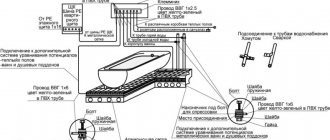
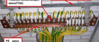
The grounding conductors are connected using grounding bars made of electrical bronze. All parts of the shield according to the TT diagram are attached to the wall of the box.
Installation of grounding on a home-made overhead line is carried out using a sledgehammer, with which the grounding conductor is driven into the ground. Driving in factory parts is done using a jackhammer. In both methods of grounding installation, it is advisable to use a stepladder. Manual welding is used for welding rolled ferrous metal.
Standards for grounding systems
Requirements for portable grounding are dictated by the following circumstances:
Conductor cross-section
In order to comply with mechanical strength parameters, the smallest cross-section of conductors should be:
Smaller sections are not allowed by regulations. For electrical installations with voltages from 6 to 10 kW and high short-circuit currents, conductors with extra-large cross-sections (from 120 to 185 square millimeters) cannot be avoided. It is very difficult to work with such sections, and therefore in such situations it is possible to use several portable grounding conductors, which are placed parallel in close proximity to each other.
To calculate the required cross-section of conductors, the formula is used:
The indicator tf can be considered identical to the time delay of the main protection of the relay connecting an electrical installation. The installation switch must stop a short circuit at the portable grounding site. It is necessary to avoid situations where it is necessary to make groundings of different sections for switchgears of the same voltage, therefore the largest indicator is taken as the time delay.
If the network has a grounded neutral, the conductor cross-section is selected based on the single-phase short circuit current. But in the case of an insulated neutral, high thermal stability during a two-phase circuit will be required.
The requirements for portable grounding exclude the possibility of using insulated wiring, since the insulating layer prevents the visual detection of defects in the conductor cores. As a result of damage, the cross-section becomes smaller, and this can cause a short circuit.
The design capabilities of the clamps must ensure their strong fixation on conductive elements using a special rod device. The shorting wires are connected to the terminals directly - without adapters. This standard is due to the fact that adapter tips may contain low-quality contacts. Such contacts are difficult to see, but if shorted, they are susceptible to fire.
The short-circuiting wires of a three-phase grounding conductor are connected to each other and the grounding conductor using crimping or welding. The connection can also be made with bolts, but in this case additional processing will be required - solder connection. Moreover, the solder must be hard, since soldering is prohibited for the reason that heating the device during operation will lead to melting of the solder and destruction of the connection.
It should also be said about what requirements are established for the marking of portable grounding devices. All devices must indicate the rated voltage of the electrical installation, cross-section of conductors and inventory number.
Requirements for overlay areas
According to technical rules, installation of portable grounding switches is carried out on all phase elements of the area disconnected from the electrical supply. Power is switched off at all connection points from which voltage may be supplied. In this case, the reverse transformation should also be taken into account. One grounding connection must be on each side - this condition is dictated by safety requirements. The area can be protected from live elements with disconnectors, switches or circuit breakers. You can also remove fuses for this purpose.
A clear break is required between the overlap areas to separate the devices from the live elements carrying voltage. The distance between live parts must comply with safety standards.
Portable grounding in closed-type distribution systems is installed on current-carrying elements. Areas specifically designed for grounding installation are selected. The paint layer is removed from such places, and the outline is highlighted with black stripes.
Important! Areas cleared of paint must be equipped with places for installing a clamp or have clamps.
If, for technical reasons, portable grounding cannot be installed in an electrical installation, additional measures will be needed to increase operational safety. To avoid accidental transmission of voltage, it is necessary to protect the upper contacts or blades with rigid insulation or rubber gaskets.