Current to voltage converter
A current-to-voltage converter (or IU converter for short) is a circuit solution that allows you to convert the output current signal of a source into voltage.
It is also called an amplifier - resistance converter . This name was given in the technical literature because the simplest current-to-voltage converter is a resistor.
All the magic of transformation occurs according to Ohm's law. Current iin flowing through resistor R Uout to drop across it . The magnitude of this voltage is directly proportional to the product of the resistor resistance and the input current. Perhaps the formula sounds even simpler:
Uout = R × iin
The main disadvantage of using a single resistor is its non-zero resistance. This circumstance becomes a serious problem when the source is not able to provide the required voltage level across the resistor. The result will be a voltage drop at the output.
Resistance affects the operation of the converter even more if the current source has a small output operating range. Such sources include, for example, a photodiode. Its output current is units of μA.
In the case of a DAC , especially a high-quality one, using a resistor for conversion is preferable. Read why and why in the article Resistor for a DAC with current output. This is due to some phase problems of the circuits that will be discussed. Fortunately for us, sources like the photodiode do not care about phase distortion.
Principle of operation
Voltage converter 12/220V HP-1200
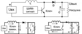
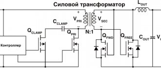
The main requirement that determines the operating principle of voltage converters is the ability to transfer useful power to the output with minimal losses (to ensure maximum efficiency). To do this, they often use loss-efficient modules, for example, electronic inverters. An electric voltage converter built according to a transformer circuit is the most convenient for considering the operating principle. The essence of its functioning is as follows:
- the potential is supplied to the input of the device from an alternating voltage generator or similar current source;
- a signal of similar shape is removed from the output of the transformer (from its secondary winding);
- if necessary, the alternating output voltage is first rectified by a special diode unit and then stabilized.
It is very difficult to achieve the required efficiency from such a circuit, since part of the transmitted power is lost in the transformer windings (due to thermal dissipation).
To obtain high efficiency from the device, key circuits operating in energy-efficient mode are installed at the transformer output. When they operate, based on high-speed switching of transistors from a closed state to an open state, power losses in the windings are significantly reduced.
Voltage converters designed to work with high-voltage power supplies traditionally use the phenomenon of self-induction. It is implemented in output ferrite cores when the current in the primary winding is abruptly interrupted. The same transistors are used as such a chopper, and the pulse voltage obtained at the output is then rectified. Such circuits make it possible to obtain high potentials of the order of several tens of kV. They are used in the power circuits of already outdated cathode ray tubes, as well as in television picture tubes. In this case, it is possible to obtain good efficiency (up to 80%).
Circuit of current-voltage converter on op-amp
The current-to-voltage converter circuit is not new at all, but it is proven and trouble-free. In general it looks like this:
iin signal current flows into the inverting input. Since the input current of an ideal op-amp is zero, all incoming current goes to the feedback R. This current creates a voltage drop across the resistor according to the same Ohm’s law.
As a result, the op-amp will try to maintain a voltage across the load resistance RN that is proportional to the input current. The gain of the circuit in this case has the dimension of resistance. Which once again explains the Soviet name amplifier-resistance converter:
K = Uout ÷ iin = R
DC to AC converters
These devices are called DC/AC inverters. They can be used as separate equipment or be part of uninterruptible power supplies and power conversion systems. The generation of alternating voltage is carried out using transistors and PWM. Periodic high-frequency opening/closing of transistors in an electrical circuit ensures a change in the direction of current flow and a sinusoid is obtained.
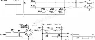
It is important not only how the voltage inverter works, but also what topology for generating a sinusoidal signal it uses. There are two main options:
Half-bridge topology with through neutral. It is distinguished by a minimal number of power transistors and a fairly simple circuit. The disadvantages include the need to use a bipolar power supply and a doubled number of high-voltage capacitors. This option is usually used for not very powerful loads (0.5-1 kW).
Bridge topology. The most common circuit in power converters. It is characterized by increased reliability, does not require large input capacitance, and ensures minimal ripple on transistors. Disadvantages include increased driver complexity and an increased number of transistors.
Converter for grounded source
Let's consider several circuits of a current-to-voltage converter using an op-amp, suitable for any case. Let's start with the converter circuit for the photodiode.
The direction of current flow is shown by an arrow, and for this case the output voltage will be:
Uout = − iin × R
The minus sign appears due to the selected direction of photodiode current flow. (Indicated by the arrow in the diagram above)
This diagram also shows an additional 1 MΩ resistor from the non-inverting ( + ) input of the op-amp to ground. The circuit will remain operational without this resistor, and the input of the operational amplifier in this case is directly grounded.
However, with a 1 MΩ resistor in the feedback circuit, for every 1 µA of input current, 1 Volt of voltage will be generated at the output. At this gain (a million times) a resistor is desirable due to the non-ideal nature of op amps.
The current-to-voltage converter is also used with signal sources connected to the power bus. This circuit is often used with elements such as phototransistors. The phototransistor consumes (passes) current under the influence of an external light source, the positive power bus.
Areas of use
The scope of application of multi-zone voltage converters is very extensive. They are traditionally used for the following purposes:
- in linear devices for distribution and transmission of electricity;
- for carrying out such critical technological operations as welding, heat treatment and the like;
- when it is necessary to supply power to load circuits in a wide variety of technical fields.
In the first case, the EMF generated at power plants is increased with the help of these devices from 6-24 kV to 110-220 kV - in this form it is easier to “drive” it through wires over long distances. At regional substations, other transformer devices ensure its reduction, first to 10 (6.3) kV, and then to the usual 380 Volts.
When servicing process equipment, voltage converters are used as electrothermal installations or welding transformers.
In industry
The most extensive area of application is providing high-quality power to the following industrial designs of consumers:
- equipment operating in automatic control and monitoring lines;
- telecommunications and communication devices;
- a wide range of electrical measuring instruments;
- special radio and television equipment and the like.
Current to voltage converter for ungrounded source
Such a converter is distinguished by the presence of a second current-sensing resistor in the signal current circuit, which is grounded. The circuit of a symmetrical current-voltage converter is similar to a differential amplifier.
As a result of the voltage drop across the grounded resistor, the op-amp input potential drops below the ground potential, and the output voltage is set to:
Uout = −2 × iin × R
A symmetrical current-to-voltage converter is an example of an operating circuit that requires an ungrounded (floating) signal source. The same photodiode can serve as such a source. In this case, the photodiode can be moved outside the board. To further minimize interference, it is advisable to use a shielded cable with the shield connected to ground.
DC voltage reduction
In the practice of powering household appliances, there are many examples of electrical devices operating on direct current. But the operating voltage rating may differ significantly, for example, if you need to get 12 V from 36 V, or in situations where you need to power the device from the USB connector of a personal computer with 3 V instead of the existing 5 volts.
To reduce this level from a power supply or other source by almost half, you can use both simple methods - including additional resistance in the circuit, and more effective ones - replacing the voltage stabilizer in the feedback branch.
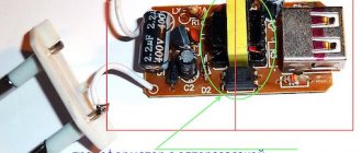
Rice. 1. Replacing a resistor or zener diode
The figure above shows an example of a power supply circuit in which you can lower the voltage by changing the resistor and zener diode parameters. This node is circled in red in the figure, but in other models the installation location, as well as the connection method, may differ. In some circuits, you can use only one zener diode to lower the voltage.
If you do not have the ability to connect to a power supply, you can get by with less elegant methods. For example, you can lower the voltage by including a resistor in the circuit or select diodes; the second option is more practical for DC circuits. This principle is based on the voltage drop due to the internal resistance of the elements. Depending on the conductivity ratio of the workload and the semiconductor element, about 3 to 4 diodes may be needed.
Rice. 2. Reducing DC voltage with diodes
The figure above shows a schematic diagram of voltage reduction using diodes. To do this, they are included in the circuit in series with respect to the load. In this case, the output voltage will be lower than the input voltage by exactly the same amount that will drop across each diode in the circuit. This is a fairly simple and affordable way to lower the voltage, but its main disadvantage is the power consumption for each diode, which will lead to additional energy costs.