Heater resistor
Self-service and repair of VAZ cars is a common occurrence for many car owners.
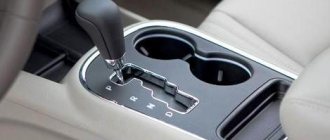
Periodic failure of some parts of the heating system is common in the “tenth” family. The most common problem is a broken heater rheostat. In the article we will look at where this element is located and how to replace it. The heater rheostat (resistor) is responsible for changing the speed of the hot air flow through manual control inside the car. If this part fails, the heater fan operates only in the 4th extreme position. Constant operation of the electric motor at high speed leads to inconvenience in using the stove and rapid wear of the fan.
What is it and why is it needed
It’s worth saying right away that replacing the Renault Logan heater resistor can be done with your own hands. There is nothing fundamentally difficult about this. But a novice motorist should find out what this element is, what it is needed for, and what functions it performs.
The main purpose of a resistor, rheostat or set of resistances is to create resistance. This is necessary to control and regulate the current strength, as well as resistance parameters.
In simple terms, this is a kind of filter. Due to the principle of operation, electricity with certain parameters is obtained at the output of the resistor. They can be adjusted by the user himself.
A resistor provides such properties by holding current, dividing and reducing voltage. These capabilities largely explain the widespread use of resistors in car designs. Moreover, it is a mistake to assume that the device is used only in the stove. This also applies to the cooling system, ignition, lighting.
If we talk about the resistor specifically for the stove, then it is part of the heating system. More precisely, it helps in controlling the operation of the electric fan of the stove.
All cars, including Renault Logan, require the use of a variable resistor. With its help, you can change and regulate the speed of the electric motor of the stove. That is, the resistor affects how fast the fan will rotate.
In the case of Renault Logan, 4 fan speeds are provided. In the zero position the motor does not work at all. At the first speed, the resistance is maximum, which is why the fan rotates slowly. As the mode increases, the resistance decreases and the fan rotation speed increases. At speed 4 there is no resistance at all. That is, the electric fan rotates as quickly as possible, since it receives power directly and not through a power-reducing resistor.
That is why, if this element fails, the stove does not work at the first 3 speeds, but turns on and turns the electric fan if you select the maximum 4 speed mode.
Since the resistance does not operate, this indicates that the resistor has burnt out. To be more precise, the thermal fuse burns out here.
Potentially it can be replaced, leaving the old resistor. But in this case there is a risk of making a mistake. As a result, if you do something wrong, the entire heating system, as well as the electrical components of the machine, can suffer.
Because of this, most Renault Logan owners prefer to completely replace the rheostat.
Location of the heater resistor on VAZ 2110-2112
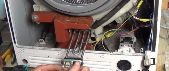
To replace a burnt-out resistor yourself, it is enough to know where the part is located, as well as to have a minimum set of tools on hand. Regardless of what year the car is, the location of the rheostat remains the same - in the engine compartment, near the heater fan. During a visual inspection, this resistance block cannot be seen, because it is hidden by a plastic cover (“frill”).
For an accurate understanding of where the part is located, here is a photo.
Reasons for rheostat failure
Despite the simplicity of the design of the heating system in VAZ cars of the “tenth” family, resistor malfunctions often occur. Let's consider several main reasons for the breakdown of this part:
- short circuit in the circuit (more precisely, low resistance of the windings in the fan motor);
- tight movement of the stove impeller caused by contamination and lack of lubrication on the mechanisms. The jamming of the stove causes the resistor to burn out;
- Constant operation of the stove in the first position. It is worth periodically running the heater at high speeds.
Also, the cause of a resistor malfunction may lie in the poor quality of the part. It is enough to install the factory version, and the problem will go away.
As a recommendation, we note that for normal operation of the heating system, it is necessary to periodically service the stove, change the cabin filter and prevent dirt and dry leaves from getting into the stove.
Sensors based on rheostats
There are direct relationships between the position of the rheostat slider, its resistance, the current in the circuit and the voltage. These features form the basis of the rotation angle sensor. Each position of the rotor in such a device corresponds to a certain electrical quantity.
Gradually, such sensors are being replaced by magnetic and optical devices. This is due to the fact that the characteristic of the dependence of angle and resistance is immune to interference from the influence of temperature. The transition to digital systems also contributes to the displacement of rheostatic sensors. Resistive meters can only be found in circuits that use analog signals.
Replacing a faulty resistance block
Because Apart from the body design, there are no differences in the mechanisms and main units between the VAZ 2110, 2111 and 2112; the instructions for replacing the heater rheostat are universal. You can repair a problem with the operation of the stove yourself if you have a couple of screwdrivers and several spanners.
The step-by-step process for replacing the rheostat looks like this:
- Open the hood and unscrew the wipers.
- Next, remove the plastic trim under the windshield (“jabot”).
- Remove the chip with wires from the rheostat and remove it from its seat.
Important! Before starting work, you should make sure that the cause of the problem lies in the resistor. The test is easy: get to the part and connect the multimeter to the power wires, then turn on the ignition. Another sign of a problem is that the stove operates only in the 4th position.
Also, as a recommendation, we note that at the time of disassembling the plastic lining, you can clean the stove cavity. When driving in the autumn, dry leaves and dirt often get into the stove, which makes it difficult for the fan to rotate.
Tips for using the stove
For several years of production of cars of the “tenth” VAZ family, engineers did not provide for the possibility of modifying the rheostat. The design with this part does not allow you to be 100% confident in the reliability of the heater. It is also worth noting that the location of the part is not the most convenient.
To ensure long-term operation of the resistor, we recommend following the following recommendations:
- use the stove in different positions and do not allow long periods of operation in one mode;
- If there are extraneous noises, creaks and whistles from the fan, it is recommended to stop its operation until the cause of the noise is eliminated.
Because The price of this part is low, and it often breaks down - we recommend carrying a spare with you in case of breakdown. We also note that in the absence of a spare part, the operation of the faulty heating element can be restored by resoldering the contacts. This method is temporary, so having instructions for replacement will not be superfluous.
Otherwise, the design of the heater in the “tenth” VAZ family is simple, so it rarely fails. The weak link in this design is the rheostat, but understanding how to replace it allows you not to think about a possible breakdown.
Source
How to change the fuse and resistor of a VAZ-2112 heater without involving specialists
It is the operation of the stove in the cold season that is the main problem of many VAZ-2112 owners. Although the heating system in these cars is relatively reliable and successful, no one is immune from malfunctions. You can fix some problems yourself, saving money and time.
There can be several problems with the heater, for example, supplying warm air only at a certain speed (the highest). In this case, it becomes immediately clear that the VAZ-2112 heater resistor needs to be replaced. Or it may be that a number of other elements do not work together with the heating system. Based on these signs, a malfunction of the safety element is determined. The work of replacing these parts is not difficult, so turning to specialists is simply pointless.
Problems with the backlight of the VAZ-2110 dashboard: causes and repairs
It’s probably no secret to anyone that the reliability of VAZ “ten” leaves much to be desired. Often, the owners of these cars have to deal with certain malfunctions. One of these problems is the lack of dashboard lighting. It is clear that the breakdown should be corrected as soon as possible. After all, going somewhere at night will be quite problematic - few people will like to move, essentially, blindly, without seeing either the current speed or other, no less important indicators.
DIY resistor replacement
To replace the VAZ-2112 heater resistor with a new one, you will need to perform a number of simple steps:
- Remove the “–” terminal from the battery to prevent a short circuit.
- We dismantle the lining, the trim from the frame on the windshield and the upholstery for sound insulation.
- The vacuum booster must also be dismantled, which will create difficulties when replacing a broken element.
- There is a block with wires on the resistor that needs to be disconnected.
- Now that access to the faulty element is provided, it is necessary to check its functionality. What if the problem of a non-working heater is not in this element, and we will replace the working resistor. To check, we will use an ohmmeter, which must be connected to the contacts one by one. If there is a deviation from the norm, you will need to change the resistor. Otherwise, you will need to look for the cause of the breakdown elsewhere.
- We remove the old element and install a new one in its place.
- The car is reassembled in the reverse order.
You already know where the heater resistor is located on the VAZ-2112 and how to replace it with a new one and can easily do this work yourself. And after these manipulations, your car’s heater will work like new. It will heat the interior at any speed and clearly respond to temperature control.
DIY fuse replacement
One of the reasons why the heating system refuses to work is a burnt-out fuse for the VAZ-2112 stove, located behind the heater. The fuse that belongs to the heating system is marked F7. The current strength is at 30A. This part is also related to the operation of the cigarette lighter, optics washer, lighting system in the glove compartment and heating on the rear window. Thanks to such a system, you can easily determine that it is the fuse for the VAZ-21124 stove that needs to be replaced - not only the heater will refuse to work, but also all the elements that were listed above.
There is nothing difficult in replacing the VAZ-2112 heater fuse, you already know where it is located and what marking it has. We simply remove the burnt out part and install a new one in its place. But fuses don't just blow. This is caused by a short circuit in the car circuit. If it is not found and repaired, the fuse will blow again and require replacement. And this is much more difficult, because in some cases it is necessary to go through the entire circuit of the car in order to detect the short one.
In these simple ways you can return the heater to its normal state and continue to enjoy comfortable operating conditions of the car during the cold season. You just need to believe in yourself and strictly follow the recommendations that were described, and when contacting a service station, you will have to wait some time (with the onset of winter, more clients) and say goodbye to your hard-earned money.
Source
Instrument lighting on VAZ 2110 does not work
Taking into account the existing Traffic Rules, the driver is obliged to turn on the headlights on his VAZ-2112 passenger car before moving off. This means that the backlight on the instrument panel will also turn on, although it is completely unnecessary during daylight hours, because the instruments can be viewed normally without it. Constantly burning instrument panel backlight lamps shortens their operating life and leads to more frequent malfunctions in this electrical circuit.
The simplest reason why the headlights do not light up is when children's playful hands, sitting in the driver's seat, touch the car controls. If they turn the rheostat knob that regulates the amount of light flux to the left all the way, then there will be practically no illumination of the instrument panel. Therefore, before you start troubleshooting, try turning this knob to the right. If the backlight works, then the problem will be easily solved. But if not, then only then will you have to look for the cause of this malfunction.
In this case, you will have to: either check whether the 5-amp fuse F1, which is located in the mounting block, is intact, or turn on the dimensions of your car, get out of it and see whether the parking lamps on the left side or the trunk lighting lamps are on, since all they receive power through this fuse. The right dimensions receive power through fuse F11.
If the left-hand side lamps are on and the instrument panel illumination does not work, it means that fuse F1 has not blown, so the next step is to check the contacts on the rheostat, with which I adjust the brightness of the instrument panel illumination lamps. There are cases when the plug comes off along with the contacts or it fails. You can check this assumption by removing the rheostat and closing its contacts directly. If the backlight lights come on, that means this is the reason.
A possible malfunction leading to loss of instrument panel illumination may be the instrument panel circuit board. This happens due to the burnout of the track on it, along which power is supplied to the backlight lamps. Considering that the instrument panel is not repairable, it will have to be replaced with a new one. And the filaments of the lamps themselves also burn out, although for this to happen on all the backlight lamps of the instrument panel at once, this is unlikely to happen.
Share this article with your friends:
Replacing the rheostat of the VAZ 2112 stove 16 valves
- To the beginning of the forum
- Forum Rules
- Old design
- FAQ
- Search
- Users
The 1-2-3 speeds of the VAZ-2112 2004 heater do not work. As I understand it, you need to buy an additional heater resistor? Is it installed under the frill and screwed into the stove body?
If someone has already changed this additional resistor, tell me, is it possible, without buying it, to repair the old one, solder and replace the resistors? Does it have a thermal fuse and can it be replaced with a fuse? If so, what amperage fuse? Thanks in advance for your answers!
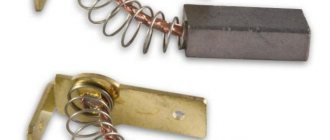
RDO 2108-8101081 is used on the oldest SAUO units, which have only 2 speeds. (0 A 1 2). RDO 2110-8118022-01 is installed on a modified heater until September 2003, the SAUO unit has 3 speeds (0 A 1 2 3). The most common malfunction in this resistance is that all stove speeds stop working, except maximum 3. The reason is that the thermal fuse is unsoldered (indicated by a red arrow), and is treated by soldering it in place. But if it is unsoldered later, you need to look in the direction of the motor, the motor takes a very large current (not lubricated, wear on the brush assembly, etc.). RDO 2123-2118022 has been installed on the latest heaters since September 2003, the SAUO unit has 4 speeds and does not have an auto mode (
0 1 2 3 4
).
Here I have a block like this, with stove speeds 0 1 2 3 4 I’ll try to repair the old one, there are only two resistors and a thermal fuse.
Added after 38 minutes 47 seconds:
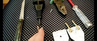
Does anyone know what thermal fuse is needed to repair this additional resistor?
?
Because, if in the second picture the thermal fuse is soldered with low-melting solder (as far as I can see), then in the third picture it is simply replaced by a fusible temperature insert (a cylinder on two antennae) and it does not unsolder, but simply burns out.
Part 1. Rheostat
Page 1 of 2Next ⇒Introduction
Current consumers (electrical measuring instruments, resistances, light bulbs, etc.) are designed for a certain power. For normal long-term operation of current consumers, the voltage and current on them should not exceed certain set values, which are called rated voltage and current values. If the nominal values are exceeded, the consumer (load) heats up and its service life decreases.
Very often there is a need to make measurements in different modes (at different current and voltage values). Often the current sources at our disposal provide a voltage that exceeds that for which the current consumer is designed. In these cases, control devices are used - rheostats and potentiometers.
When regulating the voltage across the load, it should be borne in mind that the current flowing through it will also change. We can talk about a proportional relationship between the voltage U
and current
I
, only if the load resistance
R
does not depend on either voltage or current. In most cases, this condition is met, and the load resistance can be considered independent of the current and voltage across them.
Changing the voltage applied to the load, and therefore the current flowing through it, is done either by using a rheostat or using a potentiometer.
Part 1. Rheostat
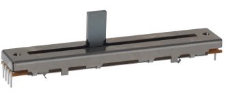
In laboratory practice, rheostats with sliding contacts are most widely used (Fig. 1). The rheostat consists of a porcelain or slate base on which bare wire made of rheotan, nichrome or other alloys with high resistivity is wound turn to turn. Above the winding there is a brass rod along which the slider D
(sliding contact).
resistance
is practically zero, ends at terminal C. As a rheostat, it is connected in series with the load through terminals A
and
C
or
B
and
C
(Fig. 2).
If the rheostat is connected through terminals A
and
C,
the current will flow through the turns located in the AC section.
When slider D
to the right (towards terminal
C,
see
Fig
. 1), the
AC
increases and the resistance of the rheostat increases.
When the rheostat is connected through terminals B
and
C,
the current flows through section
BC
and when slider
D
to the right (towards terminal
B
), section
BC
decreases and the resistance of the rheostat drops. The thinner the wire, the greater the total resistance of the rheostat and the less permissible current through it. For each rheostat, the rated resistance and the maximum continuous current are given.
Changing the current and voltage on the load using a rheostat occurs as follows. Let the load in the circuit be an electric light bulb (Fig. 2). As the resistance of the rheostat increases, the total resistance of the circuit increases ( Rtotal
), the total current (
I
) decreases, therefore, both the current through the load and the voltage across it decrease:
Rtotal = Rн
+
Rreost
,
I
=
U
/
Rtot, Un
=
I×Rn.
It should be remembered that the change in current in the circuit will not be inversely proportional to the change in the resistance of the rheostat, since in the circuit, in addition to the changing resistance of the rheostat, there is a constant load resistance. Only in those cases when Rreos t >> Rн , the total current, and, consequently, the current through the load, will change almost inversely proportional to the resistance of the rheostat. If the resistance ratio is inverse ( Rreost << Rн ), the current through the load will practically not change when the rheostat resistance changes.
Let's consider the effect of a rheostat from the point of view of changing the voltage across the load. Total current source voltage Uist
=
Un
+
Upeosti is distributed between the rheostat and the load in proportion to their resistances Un
/
Upeosti = Rn
/
Rpeost .
For example, when the resistance of the rheostat decreases, the total voltage is redistributed and at the same time the voltage across the load, and, consequently, the current through it increases. When choosing a rheostat, the most important parameters of the circuit are: voltage of the current source, load resistance, as well as permissible values of current and voltage (or limits for changing current and voltage) at the load. Current source voltage Uist
usually known.
The load resistance, if it is not indicated directly, has to be calculated based on data on the nominal parameters of the consumer (for example, voltage unom
and power
Wnom
).
To calculate a rheostat means to indicate its rated resistance and rated current. Let's consider two examples of calculation and selection of a rheostat.
1 . If the voltage of the current source is greater than the permissible voltage at the load, the rheostat is used as a ballast resistance, and its calculation is given in example 1.
Example 1. In a network with a voltage of 110 V, you need to turn on an electric light bulb with parameters of 24 V; 12 W. Calculate the rheostat that will provide the nominal glow of the light bulb in this circuit.
Let's find the current through the light bulb at nominal (normal) heat. Since the power released by the light bulb is W
=
I
×
U :
I = Wnom
/
Unom = 12 W/24 V = 0.5 A.
The same current, i.e. 0.5 A will also pass through the rheostat, since the lamp and the rheostat are connected in series. Thus, the rated current of the rheostat ( Ipeost/nom ) must be no less than 0.5 A. Since the current in the circuit should not exceed 0.5 A, and the total voltage is 110 V, it is obvious that the resistance of the entire circuit cannot be less , than: R = U
/
I = 110 V/0.5 A = 220 Ohm.
The circuit consists of a lamp and a rheostat connected in series, therefore, the total resistance is equal to the sum of the resistances of the individual sections ( Rtot
=
Rl
+
Rpeost ).
The lamp resistance can be calculated, knowing, for example, that with a rated voltage on the lamp of 24 V, the current through it is 0.5 A. Therefore, the lamp resistance: Rl = Unom
/
Inom
=
24 V/0.5 A = 48 Ohm.
Now you can find the resistance of the rheostat:
Rreost = Rtotal – Rl = 220 Ohm – 48 Ohm = 172 Ohm.
Another way of reasoning is also possible.
The total voltage of 110 V is distributed between the lamp and the rheostat in proportion to their resistances:
ul/ upeost
=
rl
/
rpeost , and Rpeost
=
Rl ×Upeost
/
Ul.
The voltage on the lamp should be 24 V, therefore, the rheostat will account for: 110 V - 24 V = 86 V.
Lamp resistance can be calculated using the formula for power as W
=
U2
/
R :
Rл= U
/
Wl
=
(24 V)2/12 W = 48 Ohm.
We get for the rheostat resistance Rreost = 48 Ohm × (86 V/24 V) = 172 Ohm.
In this case, the current through the rheostat: Ipeost
=
Upeost
/
Rpeost = 86 V/172 Ohm = 0.5 A.
Of course, the laboratory may not have a rheostat with nominal parameters of 172 Ohm and 0.5 A. You should choose a rheostat with high resistance and current values. In this case, rheostats are suitable: 200 Ohm, 1 A or 500 Ohm, 0.6 A.
Moreover, if you choose a rheostat with parameters of 500 Ohm, 0.6 A, then using this rheostat you can (if necessary) significantly reduce the voltage and current through the lamp compared to the nominal ones. So, with the rheostat fully inserted (500 Ohm), the current through the lamp is equal to Il
=
Uist
/(
Rl + Rreost
)
= 110 V / (48 + 500) 0m = 0.20 A. In this case, the voltage on the lamp is equal to Ul
=
Il × Rl = 0.20 A × 48 Ohm = 9.6 V.
The procedure for performing the work (to part 1 )
1. Obtain from the teacher a current consumer (light bulb, low-resistance resistor) to complete the practical task. Determine the nominal parameters of this load ( Rnom
,
Unom
,
Inom
,
Wnom
).
2. Calculate a rheostat to regulate the current and voltage across the load. Specific data about the current source and current control limits are specified by the teacher.
3. Draw a diagram (Fig. 4). On the diagram, indicate the initial voltage of the current source, the nominal parameters of the load and rheostat, the measurement limits of the ammeter and voltmeter. Show your calculations to your teacher.
4. Select a rheostat and the necessary electrical measuring instruments (ammeter and voltmeter) to monitor the current and voltage on the load.
5. Assemble a circuit to check the correct selection of the rheostat in accordance with the diagram in Fig. 4. Set the rheostat slider to the extreme position at which the current through the rheostat and the load will be minimal. After checking the circuit by a teacher or laboratory assistant, connect the circuit to a current source and make the necessary measurements.
6. Remove the rheostat. By changing the position of the engine, enter the results of the voltmeter and ammeter readings into the table.
| U,V |
| I, A |
7. Plot a graph of U(I).
In the report, provide a diagram, calculation of the rheostat, parameters of the selected rheostat and the results of checking the calculation, a table with measured data and a graph. Give a complete description of the ammeter and voltmeter you have chosen.
1Next ⇒
Site search:
Speed control
In order to be able to control the speed of the heater fan, there is an additional resistor located behind the vacuum booster, on the side of the heater. It is equipped with two spirals: the 1st has a resistance of 0.23 Ohm and provides the lowest, 1st fan rotation speed. The second, at 0.82 Ohm, makes it possible to turn on the 2nd speed. If this part is working properly, the driver has the ability to control the temperature in the cabin, lowering it or raising it. If it fails, then there is only one speed left for the heater - the highest. It is the additional VAZ resistor that ensures their switching, except for the last one. Therefore, in fact, the highest one works if it breaks.
Operating principle
The operating principle of all rheostats is similar. The slider rheostat has the simplest design and visually clear principle of operation. It is connected to the circuit through the lower and upper terminals. The design is made in such a way that the current does not pass across the turns, but through the entire length of the wire selected by the slider. This occurs due to reliable insulation between the conductors.
Slider positions
In most slider positions, only part of the rheostat is activated. In this case, changing the length of the conductor leads to regulation of the current strength in the circuit. To reduce wear on the turns, the slider has a sliding contact, often made of a graphite rod or wheel.
Slider rheostat device
This is interesting: Purpose and design of a manual transmission
The rheostat has the ability to operate in potentiometer mode. To do this, when making a connection, you must use all three terminals. The bottom two are used as an entrance. They are connected to a voltage source. The top and one of the bottom terminals are output. When you move the slider, the voltage between them is adjusted.
Rheostat used as a voltage divider
In addition to the potentiometer, a ballast mode of operation of the rheostat is also possible, when it is necessary to create an active load for energy consumption. In this case, it is necessary to take into account what scattering abilities the device has. Excessive heat can damage the device, so it is recommended to connect the rheostat to the network, having previously calculated the power dissipation and, if necessary, ensure sufficient cooling.
How to replace
The algorithm for replacing the heater resistor is as follows: 1. It is necessary to remove the negative terminal from the battery; 2. Remove the lining, then the windshield frame trim, remove the upholstery for sound insulation; 3. It is also better to remove the vacuum booster for ease of repair; 4. Disconnect the block with wires located on the resistor; 5. In order not to accidentally replace a device that is still in good working order (after all, the reason may not be in it), it is worth checking it with an ohmmeter, connecting it to the contacts one by one. If there are significant differences from normal readings, then it is necessary to change; 6. To remove a faulty heater resistor, simply unscrew the screw and remove the damaged part; 7. Install the new one in reverse order. Please also note that the block with wires can only be connected in one position.
That's all - your VAZ 2110 can hit the road in cold weather. You will not freeze, and you will not experience inconvenience due to the increased operation of the stove.
Source
How to determine the health of SMD resistors
SMD resistors are surface-mount components, the main difference of which is the absence of holes in the board. The components are installed on the current-carrying contacts of the printed circuit board. The advantage of SMD components is their small dimensions , which makes it possible to reduce the weight and size of printed circuit boards.
Testing SMD resistors with a multimeter becomes more difficult due to the small size of the components and their labels. The resistance value on SMD components is indicated as a code in special tables, for example, the designation 100 or 10R0 corresponds to 10 Ohms, 102 indicates 1 kOhm. Four-digit designations may occur, for example 7920, where 792 is the value and 0 is the multiplier, which corresponds to 792 ohms.
A surface mount resistor can be checked with a multimeter by completely desoldering it from the circuit, leaving one end soldered on the board and lifting the other with tweezers. After this, a measurement is carried out.
Hi all. I didn’t think that I would have to write the next entry so soon, but circumstances force me to.
Even when I bought the car, not all heater positions worked for me. I don’t remember exactly how it worked, it seems like only positions 2 and 4. Sometimes the 1st one could work, but this is rare. I don’t even know how the speeds worked in the last year.
Since the interior was disassembled and the dampers were being glued, I decided to check the heater resistor so that I wouldn’t have to get into it after assembling the interior.
Problems with the VAZ 2112 stove and its repair
The design of the VAZ 2112 stove heater differs from the previous VAZ-2108, 2109 family. When the engine is running, the radiator temperature should correspond to the general temperature of the cooling system. This means that the damper is always open and the supply of antifreeze (antifreeze) does not stop. The control system is electrical; processes are controlled by electronic sensors and controllers.
The center console has two control levers and one regulator. The driver, as necessary, sets the air temperature in the cabin, activates the desired mode (speed) of the fan, and directs the air flow to heat the glass and legs. A special electric thermometer installed in the ceiling controls the temperature. As soon as the temperature drops, the controller transmits a signal to the micromotor reducer, the heater is activated, and a flow of warm air enters the cabin. A malfunction of one or more units causes a breakdown, the VAZ 2112 stove does not heat well, and prompt repairs are required.
The device of the VAZ 2112 stove
Heater parts
- electro-pneumatic valve;
- front housing;
- water deflector;
- control valve;
- back of the case;
- radiator;
- radiator casing;
- lid;
- resistor;
- Electrical engine.
Heater ducts and controls
- Rear heating ducts.
- Plastic lining of the tunnel.
- Foot heating channels.
- Ventilation nozzles of the central part.
- Side nozzles.
- Heated front doors.
- Mechanical heating lever.
- Distributor housing.
- Damper for heating feet, windshield.
- Heater.
It is important to know. Differences in the design of the old and new VAZ 2112 in the shape of the heater radiator, the SAUO controller, and the micro-gearbox. Conventionally divided before 2004 and after. When purchasing, be careful not to hand over unnecessary parts.
From the above it follows that the heating system of the VAZ 2112 operates separately. The VAZ 2112 stove pumps air at the required temperature into the cabin. The pipes supply flow to heat the windshield, passengers' feet, and rear row of seats. Deformation of the dampers and deflectors creates an obstacle to the air flow, so the stove does not blow well and requires diagnostics.
Characteristic symptoms of malfunctions
In practice, there are five most common signs:
- The VAZ 2112 heater does not work, it constantly rotates at one stable speed;
- Temperature is not adjustable;
- The air flow control flaps are fixed and cannot be adjusted;
- Sensor - regulator on the ceiling is in a faulty state;
- Unstable operation of the ACS controller (automatic heater control system)
- Antifreeze leaking from under the radiator.
Trouble-shooting
Checking the cabin air temperature sensor
You can check the serviceability yourself; special skills are not required. Carefully remove the sensor from its original place. We find the contacts on the back side. Using a multimeter, apply a voltage of 1.2V. We set the regulators of the automatic heater control system to the “Min”, “Max” positions. The motor should not be activated.
The second method is to turn off the cabin air sensor. Check fan speed settings. The first speed (“A”) should be inactive.
Video: Heater VAZ 2110, 11, 12. Design and principle of operation.
Checking the proper operation of the automatic control system
The proper operation is checked with a multimeter. The voltage at the terminals of the pink and brown wires is measured, the ignition is activated. Smoothly turn the temperature regulator; the arrow on the multimeter display should show an increase in voltage.
On old-style heaters, at maximum voltage, the controller value remains unchanged. Take this into account so as not to make hasty conclusions about the malfunction of a particular unit.
The cause of controller malfunction may also be deformed dampers. To verify this and eliminate the breakdown, we disassemble the heater.
Prevention of the damper of the heating system of VAZ 2112
To be precise, two dampers are subject to inspection; this is the number of them present in the VAZ 2112. The cold air intake is regulated in the upper part. In the lower part, warm (hot) air is supplied to the car interior. Due to wear on the drive mechanism, the damper opens halfway or partially, the air flow is reduced, and the interior is not heated sufficiently.
Calculation of conductor resistance. Rheostats
In previous lessons we talked about electrical resistance. Let us remember that this is a physical quantity that characterizes the properties of a conductor to prevent the passage of electric current.
Having introduced a new quantity - resistance, we still have not answered one very important question: on what factors does the resistance of a conductor depend?
Analyzing the nature of electrical resistance, it can be assumed that the resistance depends on the length and thickness of the conductor, as well as the material from which it is made.
As usual, let's check the validity of this hypothesis experimentally. To do this, we use a circuit consisting of a current source, an ammeter and a panel with the conductors under study. The panel has a nichrome wire fixed at the top (a special alloy from which heating coils are made) with connection terminals at the ends and in the middle .
Below it, in the middle of the panel, there are two other nichrome conductors folded together.
And in the lower part there is reinforced iron wire of the same diameter as the upper nichrome ones. For convenience of alternate switching, the left ends of all wires are connected to each other and one of the source wires is connected to them. By touching one by one another wire coming from the source to points B
,
C
,
D
and
E
, we can include any of the conductors in the circuit.
From which we can draw the first conclusion: the resistance of a conductor is directly proportional to its length.
Then compare the current in the first dimension (that is, in a full length nichrome wire) with the current in a double wire, which is the same length but has twice the cross-section.
As you can see, when the cross-section is doubled, the current strength doubles, that is, with a larger cross-section (twice) the resistance is also half as much, which leads us to the conclusion that the resistance of a conductor is inversely proportional to its cross-sectional area.
You probably already guessed why the lower iron wire is used in the installation: it is the same in length and cross-section as the upper one, but is made of a different material.
By connecting it to the circuit, we will see a sharp increase in current strength, that is, its conductivity is much greater than that of a nichrome conductor, and, therefore, less resistance. From here we draw the third conclusion: the resistance of a conductor depends on the substance from which it is made.
Now we have the opportunity to derive a formula for calculating the resistance of a conductor. It is not difficult to understand that on its right side there will be three terms: length in the numerator (direct proportionality), cross-sectional area in the denominator (inverse proportionality) and, of course, a special coefficient reflecting the conductive properties of the substance.
Thus, the resistance of a conductor is directly proportional to its length, inversely proportional to its cross-sectional area and depends on the material of the conductor:
Coefficient ρ
, standing in the formula, is called
the resistivity of the substance.
In other words, this is a characteristic not of the specific conductor in question, but rather of the substance from which it is made.
It is equal to the resistance of a conductor with a length of 1 m and a cross-sectional area of 1 m2.
In SI, resistivity is measured in Ohm-m
. Since in practice the length of conductors is usually measured in meters, and the cross-sectional area in square millimeters, it is convenient to write the resistivity in the form:
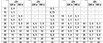
Resistivity values for various substances are presented in the table:
The meaning of the resistivities given in the table is simple. If for nichrome the resistivity value is 1.1 ∙ 10−6, then this means that a nichrome conductor with a length of 1 m and a cross section of 1 mm2 has a resistance of 1.1 Ohm.
Be careful and always look at the resistivity unit when using tabular data.
The resistivity values of substances are given for a temperature of 20 °C, since the resistance of conductors depends on temperature (which you will learn in more detail in high school). We only note that as the temperature increases, the resistivity increases, and as the temperature decreases, it decreases.
So a sensation at the beginning of the twentieth century. was the discovery of the phenomenon of superconductivity. It lies in the fact that with very strong cooling (to approximately −270 °C and below), the resistance of some metals sharply decreased to zero. At the same time, superconducting metals did not heat up even with a very high current strength in them.
Very often in practice it is necessary to change the current strength in the circuit, gradually increasing or decreasing it.
You can change the current strength by changing the resistance of the circuit. Devices that allow you to do this smoothly are called
rheostats.
You can demonstrate the principle of operation of a rheostat using ordinary wire, preferably nickel or nichrome, since they have a high resistivity.
When such a wire is included in a circuit, one contact is stationary, and the other can move along the wire. The ammeter shows how the current in the circuit changes when the moving contact moves. Obviously, the larger the part of the wire included in the circuit, the greater the resistance of the wire and, therefore, the less current in the circuit.
In practice, a wide variety of rheostats are used. But what all rheostats have in common is the use of a long wire with high resistivity.
Let's take a closer look at the slider rheostat that you will work with in class. Its appearance and symbol in the diagrams are presented in the figure.
In this rheostat, nickel wire, coated with a thin layer of scale, is wound around a ceramic cylinder. Scale allows you to isolate the turns from each other. A slider can move along the metal rod located at the top. The slider contacts are pressed against the winding turns, and as a result of friction, the scale layer under the contacts is erased. The electric current in the circuit passes from the turns of wire to the slider, and through it to the rod, at the end of which there is a clamp. Another clamp is connected to one of the ends of the winding. Thus, the current passes from one terminal to another through the turns of the winding, the number of which can be changed depending on the position of the slider.
An example of solving a problem.
Task.
When a nickel conductor with a cross section of 0.3 mm2 is connected to a current source with a voltage of 6 V, a current of 0.3 A passes through it. What is the length of the conductor?