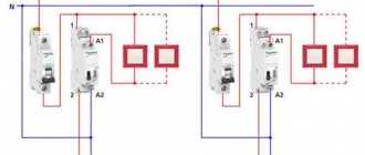
Connection diagram for a wired switch with 2 places. Do you know all the advantages and disadvantages of this wiring diagram? 3 important connection nuances
TEST:
If you decide to implement the wiring diagram described in this article, it will be useful for you to take a short test to make sure that you are ready to go.
How many contacts does the PV have?
- One;
- Three.
Explanation: The PV contains three contacts. One of them is “common”, and the other two are connected to the next PV.
There is no light in the room. First, the button of the first PV was pressed, then the second, and after that the first again. Will the light stay on after these steps?
- Yes;
- No.
Explanation: Yes, because after the third action, the phase voltage will reach the light bulb.
Can a PV circuit be implemented to operate two lamps?
- Yes;
- No.
Explanation: Yes, two-button PVs are used for this.
Electric lighting is an indispensable companion of any modern apartment. Light control is carried out using switches: there is one switch for one light source (ordinary light bulb, or several lamps). But this does not always suit the owners of the premises for some reasons. That is why the question arises, how to make it possible to turn on a light bulb from two or more places at once? In this material we will give a detailed answer to this question, and also provide a diagram of such a connection, and tell how the PV circuit works.
Why might you need a PV light circuit for 2 switches?
Situations when it is necessary to implement such a pass-through switch circuit in a room or other premises are very diverse. For example, a large bedroom. It is very convenient to place a light switch at each bed so that each resident has control over the lighting. Plus, you won't have to walk to your bed in the dark. When you enter the room, you turn on the light, and after you take your place in the bed, you turn it off.
It is also beneficial to use a similar scheme in small houses of 3-5 floors. If you make a light switch in the front door for each floor separately, this will result in the need to assemble unnecessary control circuits.
When using a pass-through switch from two places, the resident of the house will turn on the light when entering the entrance, and turn it off while on his floor.
Another example is a large office with several workstations. Having the ability to turn off/on the light from two or more points at once makes such an office much more comfortable.
Two-key switch and its connection, diagram and photo
In a room with several lighting fixtures or a chandelier with several bulbs, you simply cannot do without a two-key switch, which allows you to regulate the lighting level in a certain way: one or more light bulbs can be connected to each key. We will look at connection diagrams for two-key switches for two or more light bulbs.
In addition, this is a more compact solution than installing several conventional switches. By pressing one key, we turn on one light bulb (lamp) or a specified group of light bulbs (lamp); the second key is “responsible” for other lamps or lamps; Pressing both keys turns on all lighting. As you can see, everything is simple.
However, installing a double switch can be understandably confusing. More precisely, its connection to the network. Therefore, now we will analyze the whole process in more detail.
The principle of operation of a switch with two keys is simple: the live phase wire is connected alternately or simultaneously to both wires leading to electricity consumers by closing the terminals, providing the result described above. The prepared ends of the wires (exposed to a sufficient length) are connected to the terminals using screws or special clamps.
Let's get started installing a switch with 2 keys
Connecting electrical appliances, including switches, must be done in conditions of good daylight and always with a previously de-energized network.
Please note: first, be sure to turn off the power supply!
In addition, the necessary tools - Phillips and flathead screwdrivers, pliers - must have insulated handles. You will also need a sharp knife and high-quality electrical tape.
First you need to draw a wiring and connection diagram and lay out the wiring, after which you can start working on the switches themselves.
The wiring is laid openly (on top of the wall) in special corrugated pipes or in a closed way (internal wiring) in grooves specially made in the wall, which are then plastered. Wire connections are made in special junction boxes.
Three wires should go directly to the switch:
- one incoming, phase wire, to which voltage is applied - it is determined using a special probe screwdriver, for which you need to turn on the electricity, and after the phase wire has been identified and marked in a convenient way, the network must be de-energized again;
- two outgoing ones, leading to consumers (light bulb sockets in lamps).
Connection
Thoroughly strip the ends of the wires of insulation, about 1 cm. If the wires are multi-core, press off the exposed part with a special crimper.
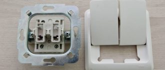
Carefully inspect the terminal block: the input terminal near the hole where the wire is inserted is marked with either an arrow or the Latin letter “L”. If the input terminal is marked with a letter, then the output terminals, in turn, are marked with arrows.
Connect the output wires to the appropriate terminals - as a rule, the end of the wire inserted into the hole is pressed with a screw using a screwdriver. At this stage, you can decide which lamps (light bulbs) will be turned on/off with which key by connecting the corresponding wires to the right and left terminals.
Next, in the same way, we connect the phase wire into the input hole and insert the switch into place in a special socket box, evenly pressing the right and left screws of the side stops. Then we replace the keys and check the operation of the assembled circuit.
Two-gang switch with backlight
Two-button switches with dimmers (backlight) are very convenient for searching in a dark room, especially if the switch is not located right next to the door, but in another place in the room. In order for the backlight to turn off, it is enough to connect one of the two wires leading from the indicators mounted in the keys at the top to the phase contact, and connecting the one coming from the bottom to one of the contacts going out to consumers. As you can see, there is nothing complicated in this question either.
By following our instructions and being extremely careful, you can connect several lighting fixtures and other electrical devices via a two-key switch.
What does a pass-through switch with 2 or more places look like?
Schemes of pass-through switches
It is impossible to distinguish a switch connected to such a circuit from the outside. This is an ordinary one-button switch/switch. There is a two- or more-button design, used when the lighting is more complex, and each button turns on a specific lamp. Instead of a push-button switch, a touch switch is used, but the principle of operation remains the same.
Advantages and disadvantages of the PV scheme from 2 places
This connection scheme has advantages and disadvantages. They follow from the very essence of the operation of such a switch. The benefits include:
- Increased comfort level. From the examples given above, it follows that the use of the scheme allows you to get rid of the inconveniences that arise in everyday life;
- Ease of execution. This electrical circuit is very simple to implement and does not require the use of any additional specific equipment;
The only disadvantage of this implementation of lighting control is the excessive consumption of electricity. Let's remember the above example about the entrance. Having entered it, a person turns on the light, and having already climbed to his floor, turns it off. The lighting will continue to operate on all floors until the occupant of the building presses the switch. Such an expense cannot be impressive, and when it comes to small rooms, it is completely absent.
Preparatory work
No matter how many keys your switch has (one, two or three), the preparatory work will be the same.
To begin with, you need to install a general distribution box and a mounting box for the switching device in the room; it is also called a socket box:
- If the walls in your room are made of PVC, plasterboard sheets, wood or MDF panels, install a special bit with serrated edges on a drill and make a hole. Insert the mounting box into it and fix it to the wall using self-tapping screws.
- For concrete or brick walls, make a hole using a hammer drill or drill with an attachment that works on concrete surfaces. But in this case, the mounting boxes must also be fixed using gypsum or alabaster mortar
As a rule, the installation of holes is carried out simultaneously with the laying of grooves. This is done purely for aesthetic reasons; there is a lot of dirt from such construction work, and it’s better to spray it once and clean it up. Grooves are grooves in the wall surface into which connecting wires will then be laid. They can be done using various tools:
- Hammer and chisel. This is an old ancestral method, its advantage is the complete absence of costs for purchasing tools (every man has a hammer and chisel). The disadvantage of this method of gating is that it takes a lot of time and effort.
- Bulgarian. This tool is often called the worst of the best. It’s convenient that grooves can be made quickly and without much effort. But it is from the grinder that there is a lot of noise and dust, and besides, it is not possible to make grooves of the same depth along the entire length, and it is almost impossible to work with the grinder in the corners of the room. So choose such a power tool as a last resort.
- Hammer. All you need is to purchase a special attachment for it - a strober or a spatula. In all other respects there are no shortcomings, it’s fast, convenient, the grooves are more or less even.
- Wall chaser. This is the ideal tool for this type of work. Works efficiently, safely and quickly. The grooves are smooth, there is no dust, since the wall chaser is connected to a construction vacuum cleaner. They are comfortable to work with and the tool does not make much noise. The only drawback is the high price. But there are services where you can rent a wall chaser.
Briefly about gating walls using the tools listed above is described in this video:
It is necessary to lay two-core wires into the grooves and fix them with cement or alabaster mortar.
So, the preparatory work is completed, the boxes are mounted, the wires are laid, and you can connect the light bulbs and switch.
Scheme of a pass-through switch from two places
PV electrical circuit
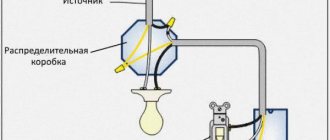
The figure shows the simplest electrical circuit for controlling lighting from two places using pass-through switches. The numbers 1 and 2 indicate the switches themselves. The phase wire is highlighted in red - that is, the wire through which the voltage flows. The diagram simplifies a single lamp as a light source, but more complex lighting is allowed in its place.
The figure shows how the PV circuit works: when you press any of the switches, the light will turn off/on. If the first switch transmitted voltage to the lamp, then pressing the second switch will turn off the light - at this point the phase wire will be “broken.” The reverse is also true. The diagram shows the situation when both switches are off. The light will not be active in any button arrangement. But what will happen in other situations? Let's consider each of the possible options.
In this diagram, first the first switch was pressed sequentially, and then the second. The green arrow shows how the contact acts after pressing the second button. It cuts off the flow of electric current, so the light bulb becomes inactive.
Following this, the first switch was turned on again. The light bulb will light up again - the phase voltage will reach the light source. After pressing the first button, the light will go out.
This is how the electrical circuit of a pass-through switch works from two places to one lamp. Its mechanism is quite simple and understandable; it is briefly described as follows:
- If both switches are on, the light source is active;
- If one of the switches is on, the light source is active.
- Both switches are off - the light source is inactive.
How to connect a pass-through switch
Switch device
The main element of the switch is the working part, mounted in the socket box. It is a metal structure with an attached drive. The drive is used to turn the device on and off. The drive is a moving contact that closes and opens an electrical circuit between two static contacts.
The first contact is called incoming: it is connected to a phase from the mains. The second contact (outgoing) is connected to the phase conductor coming from the lighting device. When the switch is positioned correctly, both fixed contacts are initially in an open state. When you press the device button, the moving contact provokes the closure of both fixed contacts. As a result, current flows through the closed circuit of their electrical network to the light bulb, and it lights up.
To ensure safety, the working part of the switch is housed in a housing made of dielectric material. The cases are made of plastic or porcelain.
Other components of the switch are the frame and keys. These elements are usually made from plastic. The keys are fixed on the drive of the working part. Moving as a result of pressing, the key changes the position of the contact, which leads to turning the light on or off.
The frame is designed to prevent a person from accidentally touching the switch contacts. In other words, the frame acts as a barrier between the energized elements and the person. The frame is fixed with screws or latches made of plastic.
The only difference between a two-key device and a single-key device is the presence of a pair of output contacts. Each contact is connected to a phase conductor of one of the lamps.
Application of a switching circuit from 2 places
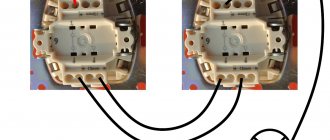
Each of the switches has two terminals. To implement the above-described scheme, it is necessary to find in each of them that contact terminal where the contact is fixed on one side. This terminal is called “common”. In one of the switches, phase voltage is connected to it, and in the other, a wire from the lighting source is connected.
The remaining terminals are connected to each other. The connection sequence is any. The blue color in the diagram indicates the neutral wire. It is routed directly to the light source from the junction box.
There are five wire connections in the junction box.
3 safety tips
When implementing an electrical circuit, you should remember 3 nuances:
- In order to determine which wire is phase, use a special probe.
- You should not use wires made of different metals when connecting them “twisted”. Due to the potential difference, a fire is provoked;
- When working, use thick rubber gloves.
Simple connection diagram from four places
The principle of operation remains the same. But the circuit also includes two additional crossover switches necessary to ensure the connections of all contacts.
PV connection diagram for 4 points
The operation of the cross switches is independent of the others. They can transmit voltage to the light source even if the pass-through switch buttons are in the inactive position. The schematic image shows that if the light is on, pressing any of the buttons will turn it off. The opposite is also true.
This scheme can be expanded to any number of lighting control locations. But the main principle remains the same: at the beginning and end of the path (to the light bulb) of the phase wire there are two pass-through switches. Between them are cross ones. Their number is equal to the number of desired lighting control points.
Connection from an outlet
But there are times when it is necessary to connect an additional lamp with a separate switch. Then it is possible to install wiring from an existing outlet. It makes no sense to discuss the choice of method of management (external or internal) now; this is not relevant to this topic. It is more logical to consider connection options. When installing a single-key switch, no difficulties arise; you only need a two-wire wire and the switching device itself.
If the voltage breaker is installed above the socket, then the neutral and phase wires are removed from it. The phase is interrupted inside the switch, while the zero remains intact. The rest of the lighting equipment connected to the circuit is powered according to the above circuits.
Connection diagram from the socket
With a similar installation of a two-key switch, three wire strands are required (output - zero, phase, phase), and if the breaker has three keys, then 4 wires are needed (zero and 3 phases).
Five most frequently asked questions
Is it possible to control several lighting sources from two places using PV?
Yes, such an implementation is possible. The double PV circuit for two lamps will differ only in that each switch will have not one button, but several (according to the number of lamps). Each button will only regulate the operation of the corresponding light bulb and will not affect the operation of the others.
Is it possible to control a light bulb from three or more places using PV?
It is impossible to implement such a scheme using only pass-through switches. To solve this problem, parallel switches are additionally implemented, which allow you to increase the number of lighting control locations to any desired number.
How is a pass-through switch different from a regular one?
The principle of operation of a conventional switch is quite simple - when you press the button, it either interrupts the electrical circuit or, on the contrary, transmits the electric current further. PV works more difficult. Pressing the button switches between different contacts. The final result (whether the light bulb is activated or not) depends on the position of the other switches.
What is the difference between a pass-through switch and a parallel switch?
A parallel switch, unlike a pass-through switch, contains as many as 5 contacts, which provide a more complex lighting control circuit, which has a much larger number of options. There are only three contacts in the PV, one is common, and the other two are used to transmit voltage or break the electrical circuit - this depends on the position of the button.
What should you pay attention to when choosing a PV?
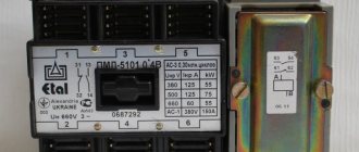
When choosing a PV, you should pay close attention to the specific type of device. They may differ in their characteristics, as well as in shape. There are open type PV (for connection with open wiring) and closed type (for connection with wiring running inside the walls). The contacts of the device are designed for a specific electric current, so when choosing a model you should focus on the expected load.
How to connect 4 PV?
Four PVs are connected using crossover switches, as described above.
Serial and parallel connection of two or more light sources
In order to connect the simplest incandescent light bulb, as in principle any other, you need to connect one contact to phase and the other to zero, the most common alternating voltage in the CIS countries, 220 volts.
Parallel connection of lighting devices means connecting two or more sources of light flux in parallel, that is, some lamp contacts are connected only to phase, and all others only to zero, as shown in Figure 1.
A current will pass through each light bulb, which will depend on its power, just as the brightness of the light flux emitted by them will also depend on the power of each lamp. Naturally, the current I will be equal to the sum of all three currents, so the cross-sectional diameter of the main conductors should be chosen according to it. This connection is considered the most common and acceptable, since it will be possible, if necessary, to add light sources in the future and they will not affect those already installed.
With a series connection shown in the figure, the current flowing through one light bulb will depend on the power of each light source, and the voltage on them will be divided by the number of lamps and, for a given input voltage of 220 volts, will be equal to 110 volts on each light source.
This connection must be made with lamps that have equal power. This can be seen using the example of two incandescent lamps. Since if you connect one lamp of 20 Watt, and another, for example, of 200 Watt, then the lamp with a lower power will immediately fail, since the same current will pass through it as in the second lamp with a power of 200 Watt, and this is 10 times its face value. This connection can be used to increase the service life of incandescent lamps, for example, in entrances and staircases. By connecting two lamps of 220 volts and a power of, for example, 60 watts each, they will burn at half power and will last a very long time. Please note that this is only possible when connecting incandescent lamps. Connecting two or more LED lamps (luminaires) and energy-efficient lamps in series is not practical, since they already have a fairly long service life.
Connecting a lamp to one switch or several
How to connect a lamp through a switch? The main nuance when connecting is that the neutral power wire is directly connected to the 220 volt network, and the phase is broken through the switch. This is done so that you can safely solve problems with the lamp socket by turning off only the switch. If two switches are connected in series, then only when both keys are pressed will the lamp light up. These types of connection of light switches are very rarely used, only under certain individual conditions.
More interesting is the connection of the so-called pass-through switch.
The essence of this circuit for connecting one lamp is that the lamp can be turned on and off from both the first and second switches, regardless of the position of each of them. For example, this is convenient, say, in a long corridor, when entering it, a person presses the switch key 2, and calmly walks along the illuminated room, having reached the end of the corridor, there is no need to return to turn off the light, but he can lightly press switch 1, installed at the end corridor, turn off this light source. With this connection, the phase also passes through the switches.
Improving lighting by installing a motion sensor
The main function of installing a motion sensor and connecting it to the lighting system is to automatically turn on the lighting without pressing the light switch button. That is, a person entered the room or into the sensor trigger zone and the light turned on; after leaving, the light turned off on its own (automatically). When choosing a motion sensor, you must first take into account the maximum power of the lighting lamps.
The connection diagram for the motion sensor is also not particularly difficult. It can be installed with or without a switch. Simply, when the switch contact is turned on, the motion sensor is removed from the lighting network, and the lighting device is turned on directly without a sensor.
In any case, when working with voltage, be sure to comply with safety requirements, and in particular:
- check the presence and absence of voltage on live elements that a person touches during installation;
- lighting power supply circuit breakers must be locked;
- carry out work with proper tools.