How can you indicate the meaning of power lines? Is there an exact definition of the wires through which electricity is transmitted? The inter-industry rules for the technical operation of consumer electrical installations have a precise definition. So, a power line is, firstly, an electric line. Secondly, these are sections of wires that extend beyond the boundaries of substations and power stations. Thirdly, the main purpose of power lines is to transmit electric current over a distance.
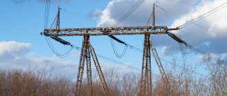
Iron power transmission poles
What is a power line?
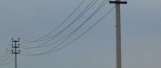
High-voltage power lines are usually installed along large highways or in uninhabited areas. This approach increases safety and simplifies the design and maintenance of power lines.
AC voltage is transmitted along power lines; it provides a greater transmission distance compared to direct current. The value is selected based on the range, for example, 35-150 kV systems are installed between cities and large enterprises, and up to 20 kV inside populated areas. Trunk power lines operate at a voltage of about 220-500 kV. They are designed to connect city power systems to a station that generates electricity.
A number of specific terms are used among specialists:
- The route is the axis of the power transmission line laying along the surface of the earth.
- A picket is a section of a route with the same characteristics (the beginning of a power line is called zero, and their installation is called a picket).
- Span – the distance between the centers of nearby supports.
- The sag is the delta between the lowest point of the cable sag and the horizontal line between the supports.
The term "wire gauge" is also used. It means the distance between a slack cable and the top of the structures located underneath it. The listed concepts relate mainly to the design of overhead power lines. It is at this stage that the safety measures for the equipment itself, the people who will be involved in its maintenance, and those passing by are calculated.
Table 1. Typical dimensions of power lines
| Rated voltage, kV | Distance between phases, m | Span length, m | Support height, m |
| 0,5 | 40-50 | 8-9 | |
| 6-10 | 1 | 50-80 | 10 |
| 35 | 3 | 150-200 | 12 |
| 110 | 4-5 | 170-250 | 13-14 |
| 150 | 5,5 | 200-280 | 15-16 |
| 220 | 7 | 250-350 | 25-30 |
| 330 | 9 | 300-400 | 25-30 |
| 500 | 10-12 | 350-450 | 25-30 |
| 750 | 14-16 | 450-750 | 30-41 |
| 1150 | 12-19 | — | 33-54 |
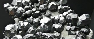
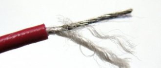
Steel-aluminum wires
The products have a resistivity similar to that of aluminum cables with the same cross-section. Structurally, steel-aluminum wires consist of steel wires inside and aluminum wires outside. Thanks to the use of steel, mechanical strength and less linear expansion are achieved when current is passed through the wire and heated, and aluminum elements act as a conductive conductor.
In such wires, additional aluminum stress is generated due to the difference in the expansion coefficient of the materials. To prevent premature wear due to vibration, it is necessary to limit stress at average temperatures.
Aluminum begins to lose strength at temperatures above +65 °C. Therefore, when choosing wires for overhead power lines, it is necessary to take into account the maximum operating temperature and allow for a reduction in strength of up to 15% for a service life of 50 years. The total loss of strength in accidents is no more than 1%.
The following grades of steel-aluminum wires are produced:
- AC - products with a steel core and one or more layers of aluminum on the outside. The products are used for laying on land, with the exception of areas with polluted air.
- ASKS, ASKP - to minimize the risk of corrosion development, a lubricant is used to fill the core. The products can be used as conductors for overhead power lines on the seashore and in industrial areas with polluted air.
- ASK - has a steel core insulated with film. The abbreviation ApSK means that this is a high-strength product.
Overhead power line wires of any brand are produced with different ratios of the cross-section of the aluminum element to the core, the parameters are selected depending on the planned load: work with an average load, and also when high-strength products are required, reinforced, lightweight and especially lightweight.
Products with enhanced strength are in demand in areas with ice walls over 20 mm. Particular strength is required when constructing large spans across water or structures. Lightweight ones are suitable for new lines in areas with an ice wall of up to 20 mm.
Increasingly, wires with a core are used, which have significant weight and a lower coefficient of linear expansion of the core.
Types of power lines
In general, an overhead power line is a whole set of devices designed for the safe transmission of electricity. This includes wires, insulators, power transmission line supports, and auxiliary fittings, including lightning protection, grounding elements, and related components such as fiber-optic communications and intermediate power take-offs. Different sections differ from each other in technical characteristics and purpose.
So, there are two large classes:
- Low voltage. Common voltage lines are 40, 220, 380 and 660V.
- High voltage. Here the range of values is larger, for example, medium voltage from 3 to 35 kV, high voltage - from 110 to 220 kV, ultra-high voltage - 330, 500 and 700 kV, ultra-high voltage - from 1 MV.
High-voltage ones are sometimes divided according to their intended purpose. For example, long-distance intersystems are used to connect individual power systems. Trunk lines are designed to transmit electricity from station generators to large hub substations. Distribution stations perform the functions of connecting the “central” substation with smaller ones located in cities or enterprises.
There is also a division according to the type of supports. Intermediate cables are installed on straight sections of the route and only hold the cable suspended. “Anchor” (“end”) supports are mounted on straight boundaries. Unlike intermediate ones, they take the main weight load, including tension due to wind and ice formation. Special racks are available that are used to change the position of the cable.
There is a conditional division of power lines into overhead and underground. The latter (cable power lines) are gradually increasing in popularity due to the ease of installation in built-up areas. In any case, they differ from each other in design, installation method, and equipment used. And we must not forget that overhead power lines still remain the main method of transmitting electricity due to their high prevalence.
There is a classification option based on the operating mode of the neutral conductor. Schemes are used - with an isolated “zero” (ungrounded), compensated (resonantly grounded) cable and effectively grounded. The first involves connecting to a grounding device through a device with high resistance, the second through inductance, and the third through “active” resistance. There are also solidly grounded neutrals.
Classification of power lines by neutral
- Three-phase networks in which the neutral is not grounded. Typically, this scheme is used in networks with a voltage of 3-35 kV, where low currents flow.
- Three-phase networks in which the neutral is grounded through inductance. This is the so-called resonant grounded type. Such overhead lines use a voltage of 3-35 kV, in which large currents flow.
- Three-phase networks in which the neutral bus is completely grounded (effectively grounded). This mode of neutral operation is used in overhead lines with medium and ultra-high voltage. Please note that in such networks it is necessary to use transformers, and not autotransformers, in which the neutral is tightly grounded.
- And, of course, networks with a solidly grounded neutral. In this mode, overhead lines with voltages below 1.0 kV and above 220 kV operate.
Unfortunately, there is also a division of power lines where the operational condition of all elements of the power line is taken into account. This is a power line in good condition, where the wires, supports and other components are in good condition. The main emphasis is on the quality of wires and cables; they should not be broken. Emergency condition, where the quality of wires and cables leaves much to be desired. And the installation condition when repairs or replacement of wires, insulators, brackets and other components of power lines are carried out.
Overhead power lines diagram
General structure of power lines
Externally, a power line, regardless of category, looks like a support on which a power cable is suspended. Fastening is carried out using special insulators that prevent leakage even in heavy rain. They allow you to hang wires on various engineering structures without the risk of electric shock to service personnel, other people, and animals. All elements are made of durable materials (concrete, stainless steel, etc.).
More details about the main parts of power lines:
- Supports are the basis of the entire structure; they are responsible for hanging wires at a certain level and holding them, regardless of climatic conditions.
- Wires - transmit electric current over a given distance in accordance with the design.
- Linear reinforcement – performs the functions of fastening individual elements to each other.
- Insulators are used to “separate” live parts of an overhead line from all other elements (supports, fittings).
It is also worth noting such an element as security cables. They are mounted in the upper part of the supports and perform the functions of protection against atmospheric (lightning) surges and lightning during thunderstorms. Structurally, the supports are divided according to the number of circuits located on them - 1 or two lines (3 wires of one three-phase network). On the anchor supports, which are the end points, the cable is rigidly fixed and tensioned to the tension specified by the design.
Intermediate supports only support it in order to prevent it from sagging below the limit, when there is a risk of contact with living objects. It is not possible to completely eliminate sagging, because a powerful, large-section cable with thick insulation is used. The same applies to security cables; they are quite strong, but because of this they have a considerable mass, making it difficult to tighten to the “string” state.
Operational benefits
In operation, uninsulated wires for power lines with Z-OR T (TRAPEZOID) laying (wires with a smooth surface):
- due to improved mechanical properties, they successfully resist snow adhesion and the formation of ice crust;
- reduce the mechanical load on high-voltage line supports that occurs when wires dance;
- dampen vibrations themselves, increasing the life cycle of the product and reducing the degree of metal fatigue;
- reduce the aerodynamic coefficient;
- increase line capacity, eliminating the problem of overloads;
- successfully resist corrosion;
- indirectly reduce heat loss during energy transfer;
- maintain integrity if part of the outer wires are damaged.
Wires of overhead power lines with Z- and T-layers can be operated both on land and at sea in atmosphere types II and III of any microclimatic region in accordance with GOST 15150 standards, UHL execution. The wire standard meets the requirements of IEC 60104(1987), wires in general - IEC 62219(2002).
When choosing products, it is necessary to consult with qualified specialists who take into account the operating features and assigned tasks.
Installation of wires for overhead power lines
According to the rules for constructing power lines (overhead power lines), it is permissible to use three types of cables - uninsulated or bare, insulated and protected. The first version of the wires is self-supporting, made of several wires, twisted into a bundle. The material for them is selected between aluminum, aluminum alloy or steel-aluminum construction (strength and other parameters must comply with GOST 839-80).
Insulated wires, like “bare” wires, are suitable for high-voltage lines with voltages up to 1 kV. Such a cable usually contains a steel core, which increases the possible span length and tensile strength under mechanical loads from icing or wind. Such brands are called self-supporting or SIP. The central core can be with or without insulation; the current-carrying cores must definitely be insulated. However, individual strands in a wire can vibrate, and by transmitting the vibration to the wires, the wires themselves will appear to be cracking.
Protected wires are intended for overhead lines, designed to transmit voltages above 1 kV, but up to 20 kV. They are often made of steel-aluminum (marked with the abbreviation AC) in order, in addition to electrical characteristics, to give the structure increased tensile strength. During the construction of power lines, aluminum is used to transmit high voltages above 20 kV. The material has high electrical conductivity and sufficient strength.
Table 2. Minimum permissible wire cross-sections
| Characteristics of power lines | Wire cross-section, sq. mm | ||
| Aluminum | Steel-aluminum | Steel | |
| Without intersections with utilities, with icing thickness, mm: | |||
| to 10 | 35 | 25 | 25 |
| up to 15 or more | 50 | 35 | 25 |
| Crossings through navigable rivers and canals with icing thickness, mm: | |||
| to 10 | 70 | 25 | 25 |
| up to 15 or more | 70 | 35 | 25 |
| Intersection with engineering structures: | |||
| with communication lines | 70 | 35 | 25 |
| with overhead pipelines | 70 | 35 | 25 |
| with cable cars | 70 | 35 | 25 |
| Intersection with railways, with icing thickness, mm: | |||
| to 10 | — | 35 | not allowed |
| up to 15 or more | — | 50 | |
| Intersection with highways, with icing thickness, mm: | |||
| to 10 | 35 | 25 | 25 |
| up to 15 or more | 50 | 35 | 25 |
Also in use are aluminum alloys - heat-treated (AH) and non-heat-treated (AN). Such wires are stronger than “pure” aluminum and at the same time retain its electrical properties. If we are talking about relatively low voltage, it is permissible to use steel cables, which have high resistance, low resistance to precipitation, but are mechanically strong. The steel wire is marked as PS.
A rare option is copper (designated M). This is the best option in terms of electrical conductivity, environmental resistance, and high mechanical strength. But copper wires are too heavy and expensive, so they are practically not used. Too large a budget will be required for the construction of power transmission line supports, the manufacture of fittings, and insulators.
Types of wires for power lines
In the energy industry, products with a wide variety of technical characteristics are used, depending on the tasks being solved; the materials from which they are produced also differ:
- aluminum – core and layers;
- aluminum – top layers, steel – core;
- aluminum – top layers and carbon composite material – core;
- with insulation (self-supporting insulated wires).
The features of a particular wire are reflected in its nomenclature designation (when using markings in accordance with GOST requirements). For example:
- A3F/S1A-Z – (A) aluminum alloy, (S) steel core, Z-shaped cross-section of wires of the top layers, (1) one layer;
- A3F-Z – aluminum alloy, without a core, Z-shaped section of the wires of the upper layers.
The presence of the letter Z means that the top layers are made of aluminum-magnesium wire with a Z-shaped section. The number before the letter is the number of layers. The outer layer of the wire has an almost smooth surface. The filling of the internal space with aluminum reaches 98.5%; such a dense arrangement ensures minimal aerodynamic resistance, due to which the mechanical stress of the wire is reduced to minimum values, and the total working cross-section of aluminum is increased - due to which the throughput of the wire increases without additional heat losses. The use of Z-layer reduces the accident rate of power lines during squally winds, ice, frost, and snow accumulation.
- High-voltage power line wires have the following design advantages.
- Z-layer - a developed non-linear contact surface between adjacent wires, which prevents the wires from falling out of the layers when they are damaged, as well as the leakage of grease from inside the wire and, as a result, the penetration of moisture to the core (for a wire with a core);
- In bare wires with Z-stranded top wires, alloys based on the Al-Mg-Si bond are used, which makes it possible to do without a steel core. This provides up to 22% weight reduction at similar values of resistance and breaking force. In this regard, a combination of high tensile strength with low weight is achieved.
- Technical advantages confirmed by calculations.
- Due to the smooth surface, ice melts off 2.4 times faster when it may occur (according to experimental data from the Institute of Electrotechnical Research in Quebec IREQ, Canada). The original and translation of the document can be found in the article;
- Modeling of ice shedding and wire dancing in the PLS-CADD software package shows a decrease in the length of vertical movement of a wire with a smooth surface in comparison with a traditional speaker of the same cross-section - by 1.6 times, the length of horizontal movement - by 1.2 times. Comparison of AC 300/66 and A3F/S1A-Z-410/117-27.6, a description of the comparison can be found in the article;
- The coefficient of resistance to the natural wind influence of such wind-loaded power line wires for a wire with a Z-shaped cross-section is 15% lower than for a wire made of smooth wires. All other things being equal, the wind force acting on the wire is directly proportional to the drag coefficient.
High-voltage power line wires with Z-layer have greater mechanical strength. Possibility of breakage due to damage occurring under external influence of wind load or snow coupling on the sagging boom. The layers retain their integrity even if several adjacent wires are damaged. Damaged elements do not unwind, which eliminates the risk of a short circuit (a phenomenon characteristic of round wire). These overhead power line wires are characterized by a smaller diameter and greater torsional rigidity. Due to these features, they are more resistant to cliffs due to icing and sticking snow.
Power line support device
The support is designed for fastening and hanging an electrical wire at a certain height. They are made from various materials - wood, reinforced concrete, metal or composite. The durability of the structure and ease of maintenance or repair depend on the design of the power line support. Therefore, wooden poles are gradually being abandoned, although they are cheaper than other options. And they are replaced with reinforced concrete, metal, composite.
Main support elements:
- Foundation – ensures the stability of the structure even on heaving soils.
- Stand – sets the height of the cable above the ground level.
- Struts - take on part of the load from one-sided tension of the wire.
- Guys – helps keep the cable horizontal.
Supports are divided into two categories: anchor and intermediate. The first ones are mounted at the beginning or end of the line, at points where the route changes direction. They are more massive and durable compared to the second type. The intermediate ones are located between the anchor ones at the same distance to maintain the wire at the same height (on straight sections). Depending on their purpose, these supports are divided into transposition, cross, branch, lowered and elevated.
There is a standard that defines how racks should look - GOST 22131-76, but practice shows that there are often cases of avoiding the mass use of standard designs. On site, service organizations adapt regulations to local landscape and climate conditions. Because of this, the materials used in the manufacture of racks are also changing. Thus, wood, even impregnated with an antiseptic, serves less than concrete goods or metal products.
Metal supports are made from special grades of steel. The individual sections are connected using telescopic or flange adapters. They are easy to manufacture, easier to ground, and easier to transport. Metal creates less load on the foundation, which means the entire structure is cheaper and more economically efficient.
But “iron” is a relatively expensive material, so the most widespread, besides wood, are reinforced concrete structures. They are easy to manufacture according to the “template” provided by the standard, so production is cheap. The only drawback of reinforced concrete is the difficulty of transporting it in finished form and the need to use heavy equipment for installation. But such racks serve for decades without changing characteristics.
Trapezoidal wires:
- increase the density of the aluminum conductor and the effective cross-section, which, in turn, increases the conductivity of the wire.
Benefits of use during construction:
- reducing the cost of the overhead line reconstruction project while maintaining weak supports by reducing tension;
- reducing the cost of the project on new overhead lines by reducing the number of supports (with increasing spans between supports) or using supports of lower height for a given size;
- savings at ice melting stations;
the ability to select two options for core operating temperatures.
Benefits during use:
- increased conductivity of the material makes it possible to reduce line losses and associated emissions into the atmosphere by 20-30%, which makes it possible to increase transmitted power with lower energy production costs and less impact on the environment;
- CFCC wires use a composite core, which provides higher strength of the wire compared to other wires and smaller sag, which allows you to increase the length of line spans;
- compact structure, smooth surface of the wire and elasticity of the core make it possible to reduce the load on supports during icing and wind loads compared to steel-aluminum wires;
- resistance to environmental influences - no corrosion or electrolysis between the aluminum wires and the core.
Design benefits
When designing power lines, wires and cables for power lines of this type:
- make it possible to use existing fittings, reducing installation costs;
- allow efficient use of domestic software packages;
- do not require replacement when crossing water barriers, since the steel core provides the wire with a very high degree of tensile strength.
Design features of wires for power lines
Electric current is transmitted only in a closed circuit, so consumers are powered by two or more conductors. According to this principle, simple overhead power lines are formed - single-phase with a voltage of 220 V. Complex electrical circuits carry out transmission using a three- and four-wire circuit with a grounded or tightly insulated zero.
The metal for making the wire and its diameter are selected taking into account the planned load of each line. The most common are steel and aluminum, which are produced by weaving several wires (for high-voltage lines) or from a monolithic core (for low-voltage circuits). The space between the wires is filled with lubricant for resistance to heat, or no lubricant is used.
Multiwire structures of high-voltage power line wires are made with steel cores. Such systems of aluminum cables, which conduct current well, are designed for high tension loads and prevent breakage.
Self-supporting SIP wires everywhere replace non-insulated structures in the construction of overhead power lines, and are used on overhead power lines, usually up to 35 kV, sometimes/rarely up to 110 kV. They consist of several aluminum cores and are widely used in organizing trunk lines and for wiring in residential buildings; they can be laid along the walls of buildings.
Depending on the purpose, choose the type of wire:
- SIP1 - with a load-bearing zero core without the use of insulation.
- SIP2 - with an insulated neutral conductor for arranging lines with voltages up to 35,000 V and a frequency of 50 Hz.
- SIP4 - the zero core is not load-bearing, while all cores are insulated. Eliminates the risk of short circuits. The products are durable, serving for more than 40 years.
To organize overhead power lines in holiday villages, SIP wires with a zero load-bearing core, which has a cross-section of up to 50 mm, are used. The number of cores is 1-3 pcs.
Power line insulator design
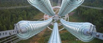
Insulators are the main protective device that prevents short circuits and leakage of electric current in wet weather. Such products are produced in accordance with standards such as GOST 27611-88, 6490-93, 30531-97, 18328-73 (the application of standards depends on the material). Structurally, they are divided into categories: pin, suspended, rod, support-rod. The first are used on lines up to 1000V, the rest are intended for power lines of 110 kV and above.
Difference in material:
- Porcelain - used 100 years ago, is now considered obsolete. And all because of their mechanical fragility, the difficulty of finding microcracks, and breakdown. This disadvantage is partly compensated for in ceramic insulators (analogous to porcelain).
- Glass is also fragile, with low impact strength, but the place where the breakdown occurred is clearly visible on them. Like porcelain, they require care during transportation, storage or installation.
- Polymer - this material is lighter and stronger than glass and porcelain, so it is cheaper both in transportation and during installation and operation. With them there is no longer a risk of damage by vandals, the plastic is not so easy to break.
The only drawback of polymer insulators is the lack of objective data on the durability of the structure. Plastic began to be used in the construction of power line insulators quite recently. Plus, it is difficult to see electrical damage on it, even if a breakdown occurs. Otherwise, plastic insulators are noticeably superior to porcelain (ceramic) and glass.
All materials can withstand severe frosts and heat well, so when choosing an option, they usually focus on cost, ease of transportation, installation, and upcoming working conditions. Thus, polymer products in the heat are capable of bending under longitudinal loads. How critical this is, you need to check with the specialists servicing a particular route. Because it is one thing to install insulators on 10 kV power lines and quite another to work with 110 kV.
Power line relay protection device
A mandatory element of any high-voltage power line is protection against accidents that could lead to a loss of power supply. This includes atmospheric phenomena, birds and animals. Separately standing racks are isolated from each other, but situations arise when leakage currents and short circuits still occur. For example, the insulation turned out to be damaged, and during a strong wind the phase began to periodically touch the neutral wire.
Features of the power line relay protection device:
- Instrument transformers control current and voltage (labeled CT and VT respectively).
- TN blocks are installed on switchgears of an electrical substation, where the primary terminals cling to the overhead line wire and the ground circuit.
- TT products are also mounted on distribution nodes, but they differ in the way they are connected to the line (the primary winding cuts into each phase).
The main element for determining the serviceability or failure of an overhead power line is a special relay. It performs two functions. The first is to monitor the quality of the controlled parameter and, at its normal value, preserve the state of the contact system. Second, immediately upon reaching a critical value (operation threshold), it changes the position of its contacts and maintains it until the parameter returns to normal.
In addition to voltage and current, relay protection and automation devices also control power. Here, known relationships between total, active, and reactive powers and their characteristic currents and voltages are used. The direction of transmission of electricity is also taken into account. It can change in a number of cases. For example, the staff switched loads and an accident occurred. In any case, the protection is triggered, turning off the power.
Devices for measuring resistance are also used on power lines. They estimate the distance to the location of the short circuit that has occurred. Because of this, such nodes are sometimes called “remote” nodes. They work on the basis of Ohm's law, calculated from the actual measured voltage and current. The frequency on the line is checked by comparison with a standard, which is constantly generated by the same relay protection device.
Power line fittings
Power line fittings refer to various mechanisms used to attach wires and insulators to racks (supports). They vary depending on the type of cable used and the application. Thus, tension fittings are intended for fastening wires to anchor structures, to tension garlands (wedge, bolt, press clamps). Their task is to maintain the horizontal level in the condition in which the maintenance personnel left it.
The selection of the type and quantity of reinforcement is carried out at the design stage. After putting the power line into operation, it is not recommended to replace it with analogues in order to leave the technical parameters within the calculated standards.
Supporting fittings are used to fasten wires (cables) to garlands of intermediate supports. They are available in the form of blind, swinging, releasing, sliding clamps. The first ones make it possible to firmly fix the wire, while the others, in case of a break, lead to a fall to the ground. The same thing happens when the garland deviates from the vertical by 40-150°. The choice of elements depends on the upcoming operating conditions.
Coupling fittings are used to connect insulator elements together to form so-called garlands. There is an assortment of staples, earrings, pestles, lugs, intermediate links, and rocker arms. Complete with them, protective fittings are used. It ensures safety during the formation of a short circuit arc, prevents the destruction of wires due to vibration (in the list of products there are horns, rings, arresters, vibration dampers).
There remain two categories of fittings: connecting and contact. The first serves to connect wires (cables) in areas where tension is applied. These are various clamps that are mounted by crimping or pressing. The second is intended for the same thing, but in areas where there is no tension load. For example, in the loops of anchor supports. Regardless of the category, materials and design are determined by standards such as GOST 51177-98, 17613-80, 51177-2017.
Product labeling is also provided there. Thus, staples are designated by the abbreviations SK and SKD, ears - U1, U1K, U2, U2K, US, USK, UD, pendants - KGP, intermediate links - PR, PRV, PRVU, 2PR, 2PRR, PTM, earrings - SR, SRS, SD, rocker arms - KT3, 2KD, 2KU, 2KL. The choice of reinforcement determines the durability, ease of maintenance of structures, and their safety for others and energy company operators.
Power line protection
To extend the maintenance-free operation of power lines, they are equipped with various protective equipment. For example, bird protection devices are popular, which prevent the risk of insulation damage and excessive sagging due to the large number of birds sitting on wire ropes. The protection also works “the other way around” to prevent the mass death of birds from exposure to electric current (according to the Decree of the Government of the Russian Federation No. 997 of 08/13/96).
Also in demand are elements of protection against:
- Atmospheric phenomena such as thunderstorms, snow, wind.
- Icing in the off-season, when ice is actively forming.
- Unauthorized connection to the line by unscrupulous citizens.
Too much ice can lead to broken wires that are only designed to carry a certain weight (plus their own weight). Therefore, ice limiters are hung on the leeward side. These same details reduce the likelihood of vibrations that appear as a result of strong wind, especially one that abruptly changes direction and comes in jerks.
Bird protection is also quite simple. It looks like a plastic cover that is placed over the joints between the cable and the insulator. Such a simple device reduces the number of shutdowns due to parameters going beyond normal limits when the relay protection and automation is triggered. And increases the service life of insulating garland parts. In critical areas it is possible to use bird scarers of the Grad A-16 Pro type.
Such equipment is capable of covering an area of about 5-7 thousand square meters. km. And everywhere ensure the absence of any birds (pigeons, sparrows, crows, seagulls), i.e. it is adapted for operation in almost any conditions, in the steppe, near bodies of water, near forest belts and groves. Devices manufactured in accordance with TU 3449-001-52819896-2013 are considered more common.
Thus, PZU-6-10kV-T is installed on pin-type insulators for intermediate supports. ZP-N2 – on horizontal shelves of corners, ZP-KP1 – used for cables with a diameter of up to 22 mm, ZP-KP2 – up to 37 mm. Such devices are selected according to the size of the birds that live within a certain habitat, so there is no universal solution for them. They must also be compatible with a specific section of the network (suitable for fastenings to insulators).
Power line grounding conductor
Another protective structure is the grounding device of power transmission line supports. It provides protection for power lines and various equipment from atmospheric and internal overvoltage. Grounding also creates safe working conditions for maintenance personnel. It is placed on supports, hooks, pins of phase wires on all lines with voltage from 0.4 kV. The standard resistance value of the grounding device is a maximum of 50 Ohms.
The rule is valid for reinforced concrete supports in networks with an insulated neutral. On 6-10 kV lines, it is necessary to ground all metal, reinforced concrete racks, and wooden supports on which lightning protection devices are installed. The same applies to power and instrument transformers, disconnectors, fuses, and other elements of the high-voltage network.
Table 3. The highest resistance of grounding devices of overhead line supports
| Specific equivalent resistance of the earth, Ohm*m | Maximum resistance of the grounding device, Ohm |
| up to 100 | 10 |
| more than 100 to 500 | 15 |
| more than 500 to 1000 | 20 |
| more than 1000 to 5000 | 30 |
| more than 5000 | 6*10-1 |
The resistance of grounding devices is selected based on the conditions specified in the table. If we are talking about an uninhabited area in soils with a resistivity of up to 100 Ohm*m, it should be no more than 30 Ohm. On soils with high resistance, more than 100 Ohm*m - no more than 0.3 Ohm. When using ShF 10-G, ShF 20-V, ShS 10-G insulators on 6-10 kV power lines, the grounding resistance in non-populated areas is not regulated in any way.
The transmission of electricity from suppliers to consumers is carried out using special structures - power lines, which include cables, supports, insulators, short circuit protection devices, and fittings. All of the listed elements are produced and installed taking into account certain standards such as GOST 13109-97, GOST 24291-90, GOST R 58087-2018, STO 70238424.29.240.20.001-2011.
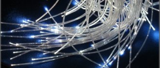
Lightning protection cables on overhead lines (lightning cables)
Lightning cables are used to ensure the safety of power lines during a thunderstorm. In most cases, cables are made of steel or layers of steel and aluminum wires. Steel is used as a reinforcing element, aluminum as a conductive layer.
On lines with voltages above 35 kV, grounding cables are indispensable
Cable designation
Lightning protection cables are conventionally designated by the material of manufacture and the nominal cross-section. An example is the S-50 cable. It is deciphered as follows: steel cable with a cross-sectional area of 50 mm2.