Production increase (technological thinning during manufacturing). Read more.
Operational increase in corrosion and wear (erosion) to wall thickness. Read more.
Strength coefficient of welded joint under pressure
The coefficient is accepted in accordance with the standards. Can be calculated automatically by pressing the button. Read more.
Bending strength coefficient of welded joint
The coefficient is accepted in accordance with the standards. Can be calculated automatically by pressing the button. Read more.
Linear weight of the pipeline and structures supporting it. Read more.
Working (normative) pressure. Set when calculating according to SNiP 2.05.06-85. Read more.
Design temperature in test condition. The average temperature of the walls (metal) along the length of the pipeline at the time of testing. Tests are usually carried out without heating the product, that is, at ambient temperature. Tysp = +20 0 C is usually taken.
Pipeline slope. Must be specified to correctly account for length calculation conditions 2 and 3
What kind of lighting do you prefer?
Built-in Chandelier
Expert opinion
It-Technology, Electrical power and electronics specialist
Ask questions to the “Specialist for modernization of energy generation systems”
How to tighten a sagging wire: troubleshooting technique, permissible sag Damaged sections of lines pose a danger, even if there is no electricity in them. If you do not know what step voltage is, then read up, this information may later turn out to be vital. Ask, I'm in touch!
Basis for calculating the sag and tension of an optical cable
In order to ensure long-term and fruitful operation of fiber-optic lines, it is necessary to calculate installation tensions and sag for the main climatic conditions.
Change of sag depending on climatic characteristics
As can be seen from the figure, in different climatic conditions the cable sag will be different. It is necessary that the safe dimensions to the ground level, crossed structures and current-carrying elements of overhead lines are observed in any mode.
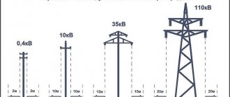
Distance between supports
If you are interested in any of our services, or have a question that requires our comment, you can contact us right now.
Expert opinion
It-Technology, Electrical power and electronics specialist
Ask questions to the “Specialist for modernization of energy generation systems”
Calculation of the sag and tension of the optical cable to ensure the specified dimensions In order to ensure long and fruitful operation of the fiber-optic line, it is necessary to calculate the installation tension and sag for the main climatic conditions. Ask, I'm in touch!
SIP tension through a dynamometer
When using a dynamometer, the tension force taken from the table alone is not enough. It is also necessary to know the given anchor span. What it is?
This is a span or spans on an overhead line between two anchor supports. Between them there can be either one or several intermediate supports.
At the same time, the calculation tables indicate data specifically for the given spans. They represent a certain average mathematical value.
This is due to the fact that the lines are not always uniform. And the distances between the supports sometimes differ by several tens of meters.
Let's say you have two anchors and one intermediate support between them. The length of the first span is 40 meters, and the second is only 10 m. It is clear that with the same tension, in a larger span the sag of the boom will always be greater.
Therefore, the gravity itself is determined precisely for the average value. The average reduced span is calculated using the following formula:
- Li is the length of one span in meters or km
- ∑Li – sum of all spans
By calculating the value using this formula, you will get the final reduced span. For our case (40m+10m) it will be 25m.
Next, using interpolation in the table, we look for the required tension. In the tabular data for spans up to 40m, the values are divided in 2m increments.
For longer distances, integer values of 40-45-50m are usually used. You will need to find the closest one.
Having found out the required value, tension the SIP on the final support through a dynamometer.
In order to do this correctly, simply monitor the readings of the scale of the measuring device so as not to go beyond the limits of this effort.
Initial data for calculating cable tension and sag
The amount of data required for a high-quality calculation of tension and sag can be perplexing, however, do not despair. Most of the listed characteristics can be easily found in technical data sheets of lines and cable certificates.
- Line passport or installation list of overhead line supports;
- Longitudinal profile of the power line (this data increases the accuracy of calculations adjusted for relief);
- Brands of wires and cables used, as well as previously suspended cables;
- A complete list of characteristics of the designed cables (diameter, cross-sectional area, permissible tension, elastic modulus, coefficient of linear thermal expansion, linear mass);
- Climatic characteristics of the area (thickness of the ice wall, maximum and minimum temperatures, maximum wind speed);
- Special conditions (river crossings, intersections with buildings and structures).
This is basic data; for a more accurate calculation, additional information may be needed (line intersections, etc.)
Formal definition
If we want to get physically correct chain lines, then it's probably better to start from the beginning.
The simplest catenary line is given by a uniquely defined equation using the hyperbolic cosine: The catenary equation has a parameter that changes the overall “width” of the curve. However, all catenary curves are similar because they are all versions of each other at different scales. Below is the change in the curve as a function of (the animation is interactive in the original article): What is hyperbolic cosine?
Many of you are familiar with the more "traditional" cosine function. Sine and cosine are defined on a circle, and their hyperbolic counterparts are defined on a hyperbola (see animation below).
Their natural area of use is the study of hyperbolic geometry.
They also often turn out to be the solution to many differential equations. In fact, and play an important role in solving the following differential equation: namely: They are also strongly related to: Show how the equation is derived!
Deriving the equation of a catenary line is a complex task that requires fairly advanced mathematical analysis.
If you're curious, Math24 has a very detailed article on Equation of Catenary showing its derivation step-by-step. The derivation of the equation begins with the assumption that for each small chain segment, gravitational forces are in perfect balance with the tension force from neighboring segments. This leads to the creation of a system of equations, when solved we get (1): This conclusion also gives us some understanding of what the parameter actually means: where:
- : density of the chain material;
- : acceleration due to gravity;
- : cross-sectional area of the chain;
- : The horizontal component of the tension force to which each chain segment is subjected. It is considered a constant because the chain line is considered to be the shape that the chain takes when the weight is evenly distributed along the curve.
How are catenary lines used?
Besides being used to recreate hanging chains, chain lines are especially useful in a variety of other applications.
Their shape is created by a careful balance between the internal tension of the chain and the force of gravity. This balance means that the weight of the chain itself is evenly distributed along its entire length. This makes inverted catenary lines the ideal shape for free-standing arches of constant thickness. Dr Tom Crawford talked about this in a recent Numberphile video, explaining how the internal structure of the dome of St Paul's Cathedral in London is supported by an inverted 3D catenary line. Catenary lines have another interesting property. They are a shape that allows the squares to move without their centers wobbling (see animation below).
How to tension a cable line?
If it so happens that this wire sagged in your area of responsibility (a branch from the main highway to your property) and the balance demarcation points are written in the agreement for the supply of electricity, then the overhead line in this area is completely your business.
This procedure is carried out with all insulators, along the tensioned line to the extreme support. After tensioning, the taps are connected and, after making sure that the line is ready and safe, they submit an application to supply voltage.
Stretching the SIP wire occurs similarly to the method described above, with the only difference that instead of insulators, special fastening fittings and anchors are used, as shown in the photo below:
Note! The wires are tensioned with a slight sag, about half a meter, to compensate for temperature changes in summer and winter.
To tension power lines, self-supporting insulated wires or cable wiring, both restored and newly laid, hand winches, ratchets or “frogs” are used, stretching the cable between spans or supports, in the area to the house or garage. Fixing in a tense state to anchors and fastening fittings. The video below clearly shows how to string a wire from a pole to a house:
And in this video you can watch the technology of tensioning a wire with a manual winch:
That's all we wanted to tell you about how to stretch a wire from a pole to a house and where to call if you find that the cable between buildings or supports is sagging. As you can see, cable line tensioning should be trusted to specialists who, with the help of devices, can quickly and, most importantly, safely complete all the work!
Mounting sag booms
Let us compare the obtained values of the required parameters of the sag line and the forces in the rope, calculated by different methods:
Expert opinion
It-Technology, Electrical power and electronics specialist
Ask questions to the “Specialist for modernization of energy generation systems”
What can be the distance between high-voltage power line supports: norms Note wires of the SIP type can be tensioned in the same way, but instead of an insulator we use special fittings for fasteners and anchors. Ask, I'm in touch!
Introduction to Catenary Lines
Of the many mathematical objects studied and described, one is very dear to many game developers. And only a few of them know its true name: catenary line .
A chain line is a figure to which a rope or chain suspended by the edges naturally leads. It is no coincidence that the name catenary itself comes from the Latin catenaria, which means “chain”. In modern games, more and more abandoned businesses and destroyed environments appear. And many of them have quite a lot of dangling wires. For example, they can be seen in GLaDOS's room from "Portal" or in "Half-Life: Alyx".
Since chain lines surround us everywhere, it is not surprising that we have become accustomed to their shape since childhood. This also means that we can very easily notice when something is hanging incorrectly. Like the complexity of skin movement or the physics of fabric, the irregular hanging of catenary lines itself creates the uncanny valley effect.
However, too many games implement chain lines incorrectly! However, the reason for this is not surprising. Although they are so easy to create in real life, their mathematical description is a real nightmare. Except for a few special cases, there are no "simple" equations for catenary generation; at least not in the form needed to decorate the level.
One standard way to create physically based catenaries without cost is to use rigid bodies and hinge joints when creating chains and ropes. This has the added benefit of being responsive to the player's actions, but at the cost of expensive calculations. Most dangling wires and cables are part of the background, and using physics to create them would be too expensive. Therefore, it is very important to be able to create static catenary lines without real-time computation.
In addition, drawing chain lines has another advantage. Let's say we want to create a real, physics-controlled dangling wire for a game. How to arrange wire segments when creating it in the game? Many developers would simply place them along the line and let the physics engine choose the equilibrium state. Drawing catenary lines allows you to initialize physically correct wires and cables already in their equilibrium state, without having to wait for them to stop in the desired position.
It is worth noting that Unity does not have built-in tools for cables and circuits, but in Unreal Engine there is a Cable Component that solves exactly this problem using the Verlet Integration (which will be the topic of my future articles). And in case you like shaders, Ross Birdsall recently created an ingenious solution for simulating spiral cords in Unreal Engine 4.
Strength condition
- Above the pedestrian area the height is not lower than 3.5 meters, and above the roadway this distance should be at a height of not lower than five meters; the input branch can be made at a height of 2.5 meters for the SIP wire.
- For lines with uninsulated conductors, the height is not less than three and a half meters above the pedestrian area, and not less than 6 meters above the roadway, a branch is allowed to be made at least 2.75 meters.
- When passing SIP near buildings, the distance from the cable to the balcony is at least one meter and at least twenty centimeters from the wire to the blank wall.
- In the case of uninsulated conductors, the distance from windows, terraces and balconies is at least one and a half meters and at least one meter along a blank wall.
- It is strictly prohibited to place overhead lines with uninsulated conductors above buildings for safety reasons.
Wire SIP-3 1×50 Permissible wire voltage Maximum wire tension Standard wind pressure Standard ice wall thickness
Wire SIP-3 1×50 Permissible wire voltage Maximum wire tension Standard wind pressure Standard ice wall thickness
Wire SIP-3 1×50 Permissible wire voltage Maximum wire tension Standard wind pressure Standard ice wall thickness
Wire SIP-3 1×50 Permissible wire voltage Maximum wire tension Standard wind pressure Standard ice wall thickness
Wire SIP-3 1×70 Permissible wire voltage Maximum wire tension Standard wind pressure Standard ice wall thickness
Wire SIP-3 1×70 Permissible wire voltage Maximum wire tension Standard wind pressure Standard ice wall thickness
Wire SIP-3 1×70 Permissible wire voltage Maximum wire tension Standard wind pressure Standard ice wall thickness
Wire SIP-3 1×70 Permissible wire voltage Maximum wire tension Standard wind pressure Standard ice wall thickness
Wire SIP-3 1×95 Permissible wire voltage Maximum wire tension Standard wind pressure Standard ice wall thickness
Wire SIP-3 1×95 Permissible wire voltage Maximum wire tension Standard wind pressure Standard ice wall thickness
Wire SIP-3 1×95 Permissible wire voltage Maximum wire tension Standard wind pressure Standard ice wall thickness
Initial data for calculating cable tension and sag
By clicking on the button, you agree to the privacy policy and allow the processing of personal data
Expert opinion
It-Technology, Electrical power and electronics specialist
Ask questions to the “Specialist for modernization of energy generation systems”
Initial data If it so happens that this wire sagged in your area of responsibility, a branch from the main highway to your property, and the balance demarcation points are written in the act of agreement for the supply of electricity, then the overhead line in this area is completely your business. Ask, I'm in touch!
Cable Sag Equation
A flexible homogeneous inextensible cable of length 2s is fixed at its ends at two points located at the same height and spaced from each other at a distance of 2l . It sags under its own weight.
The sag formula is expressed as follows:
where , where is the horizontal projection of the cable tension, and is the weight per unit length of the cable
Formula for the length of the arc, according to the shape of which the cable sags
The sag at the lowest point of the arc is calculated as follows:
In practice, the approximate formula is used
Where
What to do if you witness a dangerous sagging overhead line
Under no circumstances should you be near a wire that is sagging and try to support, tie, or bite off the cable yourself for profit. This can be fatal and dangerous because... a live line is not much different from one without voltage. In one of our articles we talked about step voltage, which is closely related to damage to the cable route. We strongly recommend that you read the material.
As a rule, each line or section has an owner or a person in charge of the energy sector, who bears full responsibility for the safe operation of the equipment entrusted to him. He needs to be informed. If this is problematic, you should call the regional energy supply organization or emergency service, the Ministry of Emergency Situations, the district administration, or the mayor's office.
Parameterization of a catenary line
If we want to learn how to draw physically accurate chain lines, then (1) may not be the best way to do it.
The reason is simple: other than change, we have virtually no control over where or how they can be placed. A more customizable equation is (2), which allows you to move the curve horizontally and vertically using two additional parameters and:
However, ideally we would have the equation of a chain line passing through two anchor points and: The parameter allows you to move the top of the chain line; when , the vertex is on the Y axis. We can shift the catenary line so that the vertex is exactly between and : In fact, it is ideal if both and are at the same level (i.e. when ). But if this is not the case, then the resulting catenary will be physically incorrect. In addition, it gives us almost no control over the amount of sag in the catenary line. So we need to approach the problem differently: we need a more “artistic” way of controlling the line.


